

Group Assignment — Week 11: Networking and Communications
This week I repurposed the PCBs I made for the Input Devices and Output Devices weeks to allow my microcontrollers to communicate across a WiFi network. I used 1 Seeed Xiao ESP32C3 microcontroller as the input to send instructions to a webapp which then sends a message to a second ESP32C3. The message is then displayed on an 8x8 LED matrix.
Generating the Code
I used Claude.ai to help me in every aspect of the coding for this project.
System Architecture
Browser (index.html)
  │
  ├─ ws://esp32c3_1.local:80/ws  ──────► esp32c3_1
  │     ↑ receives switch_press events         │
  │     ↓ sends set_switch_map config          │ ws://esp32c3_2.local:82/ws
  │                                            ▼
  └─ ws://esp32c3_2.local:82/ws  ──────► esp32c3_2
        ↓ sends display commands              LED matrix renders
        ↑ receives display_ack
Web Interface
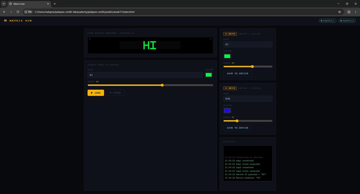
I created a web interface to allow the user to customize the text, color and speed of the LED matrix. The web interface also allows the user to see the current state of the switches and the LED matrix.
Hardware Assembly
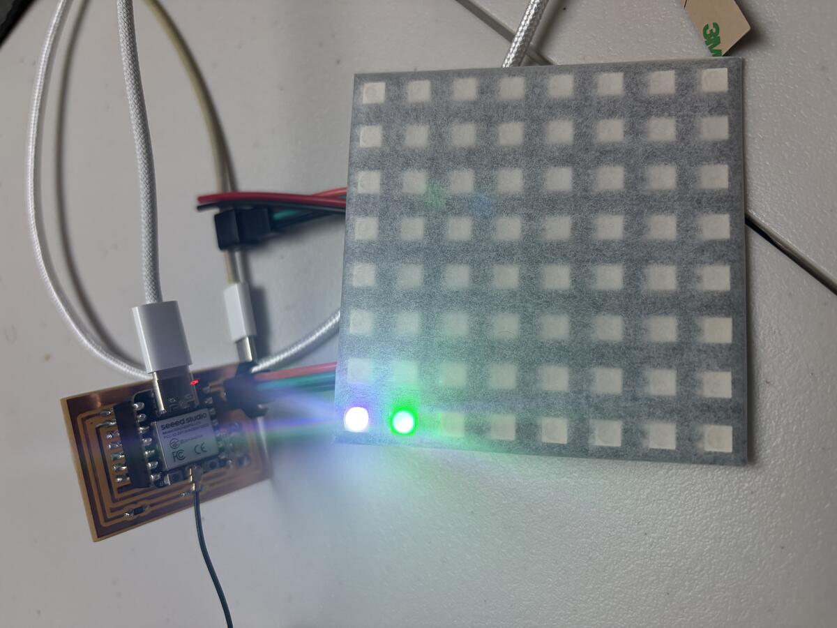
This is the failed attempt at sending the messages to the LED Matrix. The reason this did not work is because the protocols and libraries were not properly configured in the firmware for ESP32C3_2.
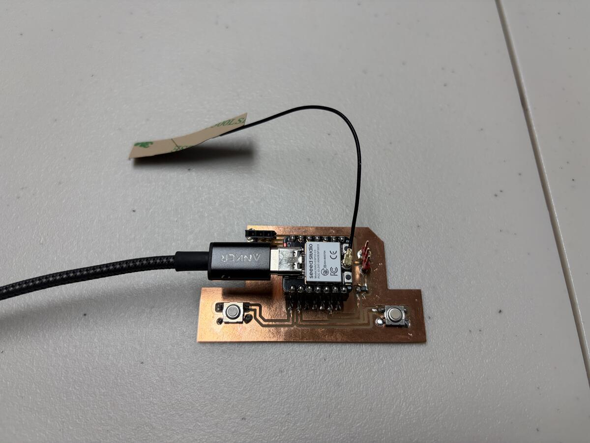
The Input Board with switch 0 on D0 and switch 1 on D1. The antenna on the ESP32C3 allows it to connect to the WiFi network.
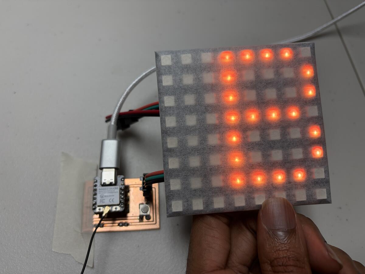
The Output Board with the LED Matrix connected to the ESP32C3.
This video shows the full series of operations working. When a switch is pressed, the interface registers the input and displays the corresponding message with options to edit the text, color and speed.