

My Final Project
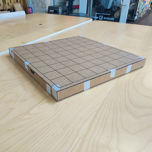
To start my Fab Academy journey, I chose to adapt a project idea I was developing for a Spring Camp Program I’m developing for Moonlighter FabLab. The theme is Build-A-Board and is all about teaching campers to come up with their own board game ideas, layouts, game pieces and rules.
Project Design Intent
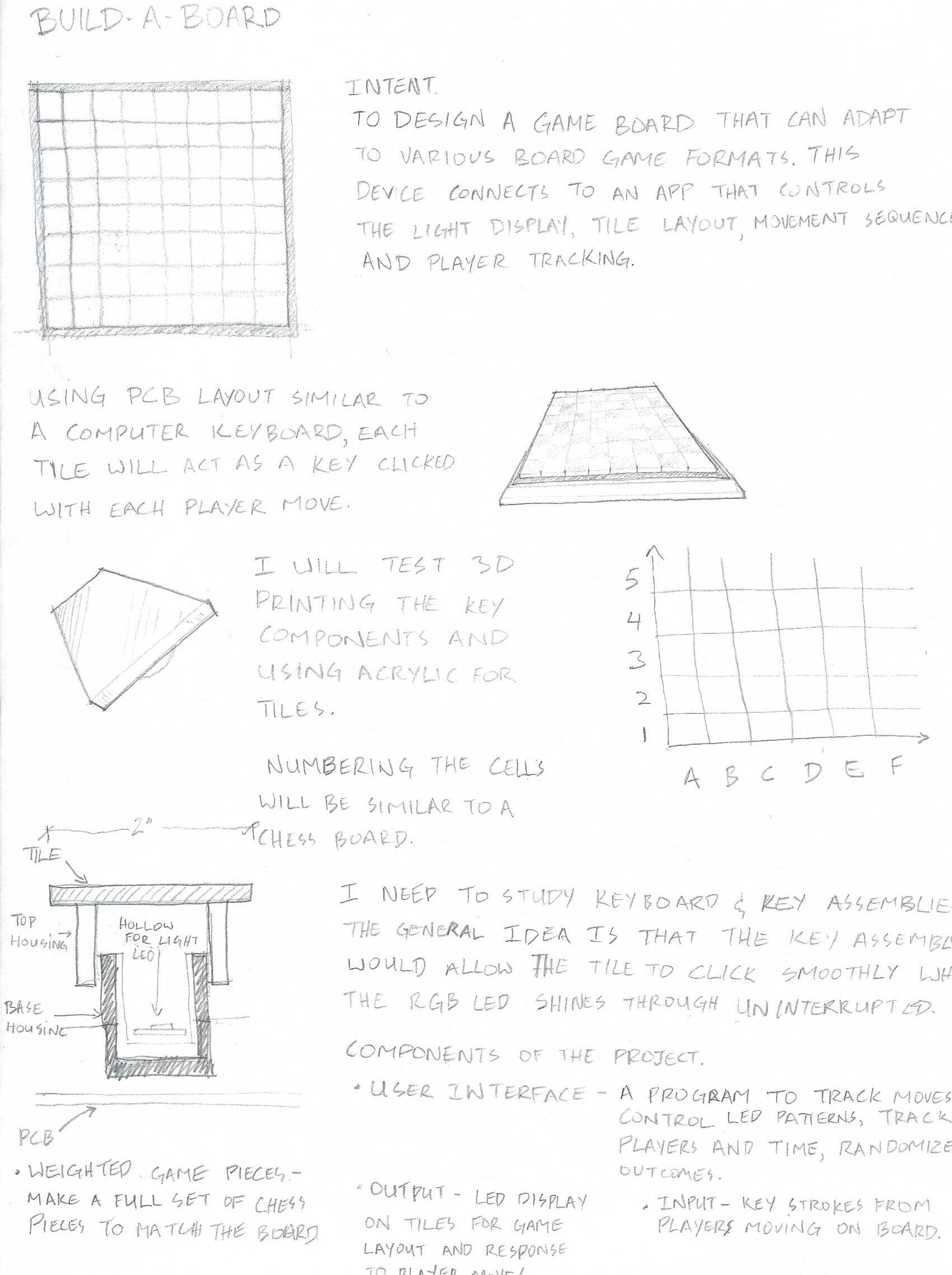
To design a game board that can adapt to various board game formats. This device connects to an app that controls the light display, tile layout, movement sequences and player tracking.
Design
Using a PCB layout similar to a keyboard, each tile will act as a key clicked with each player move. The cells will be numbered to follow a typical chess board I will need to study keyboard and key assemblies. The general idea is that the key assembly would allow the tile to click smoothly while the RGB LED shines through uninterrupted.
Components of the Project
User Interface - A program to track moves, control LED patterns, track players, track time, and randomize outcomes.
Output - LED lights in tiles for game layout and response to player moves.
Input - Key strokes from players moving on board.
Weighted Game Pieces - Make a full set of chess pieces to match the board.
While working on the concept I saw so many possibilities for integrating software and hardware. I am still at basic level when it comes to most electronics and programing so my first thought was to make the prototype using the Makey Makey interface. I was soon advised by my instructors that I would need to advance my thinking as soon as possible. I had a very enlightening conversation with my friend Alie who is a genius when it comes to electronics and LEDs. We walked through the options for sensors, types of boards, how i should breakdown the variations of the projects to save time while maximizing progress. It was this conversation that got me thinking about a keyboard functionality with integrated LEDs. This is my goal however we also discussed incorporating NFC readers to better track specific game pieces.
3D Model in Rhino 8
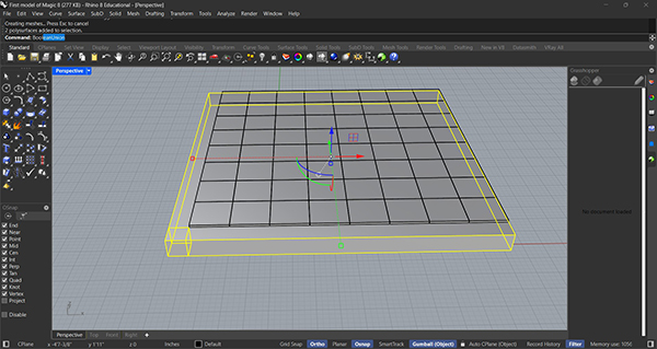
I started a 3D model using Rhino 8. I have been using this software for a few years and have learned new techniques and workflows with every new project. For my board game, I began designing the basic shape. It would be a square layout of 8x8 tiles. I used the BOX tool to create the shapes and moved them arround as needed.
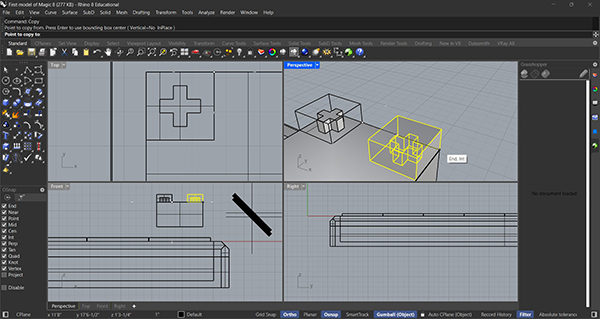
The next stage of my design was to test component details. I designed a place holder for a standard switch focussing in the connections between the switch and the tile. I used BOX tool and the boolean operations to create the final geometry.
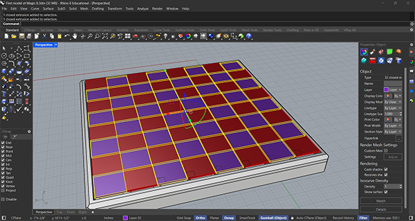
I jumped ahead and created a more detailed version of the board design. I continued using the BOX tool along with BOOLEAN DIFFERENCE to create hollow top and bottom shells. I also used the CHAMFER EDGE tool to make the design more comfortable to handle. By adding materials and colors to the tiles, I was able to prepare the model for rendering.
Rendering in Twinmotion
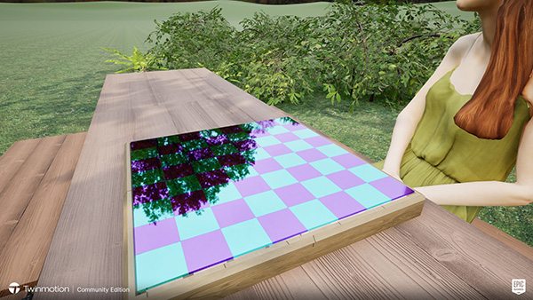
In Twinmotion, I was able to sync the 3D model and apply materials and lighting effects. I also added park scene using grass, bushes, park furniture and people. You can see the results of the project in the short video.
Logo Design in Adobe Illustrator
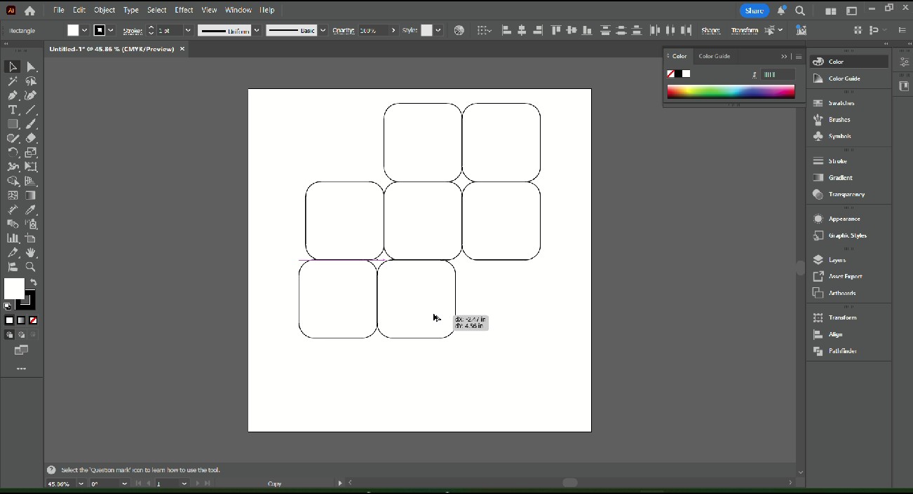
To make a logo design, I started with rounded squares in Adobe Illustrator. I have used Illustrator for several years in a variety of applications. Logo design is one area in which I have a lot of passion. The challenge for this project was to design a usable logo in as little time as possible. I arranged the square into 2 overlapping diamonds to form an '8' configuration.

I rotated the shapes to the desired orientation and used the SHAPE BUILDER tool to unify the elements. I always like to copy my elements before combining them as to maintain a backup in my file.
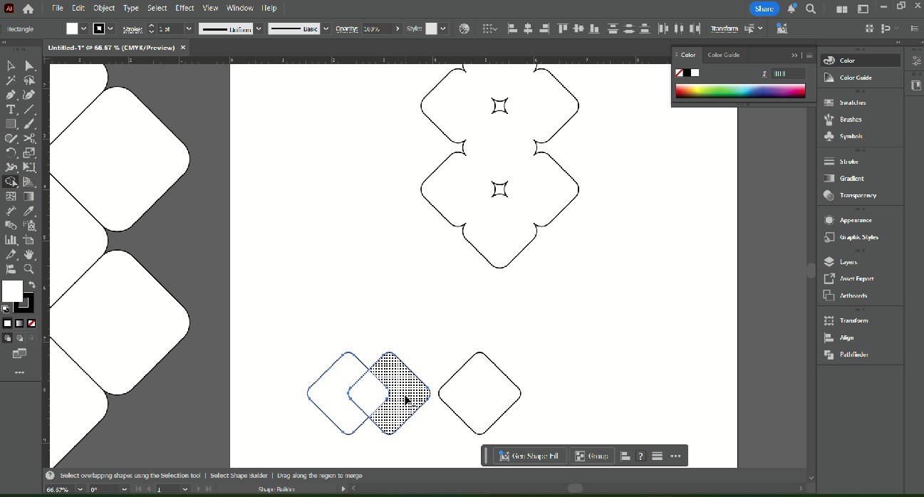
To create the font, I used the same shape as a base and arranged it to form the letters of the name of the game. I used the SHAPE BUILDER tool again to unify the elements and used the SCISSORS tool to remove the unwanted line segments.
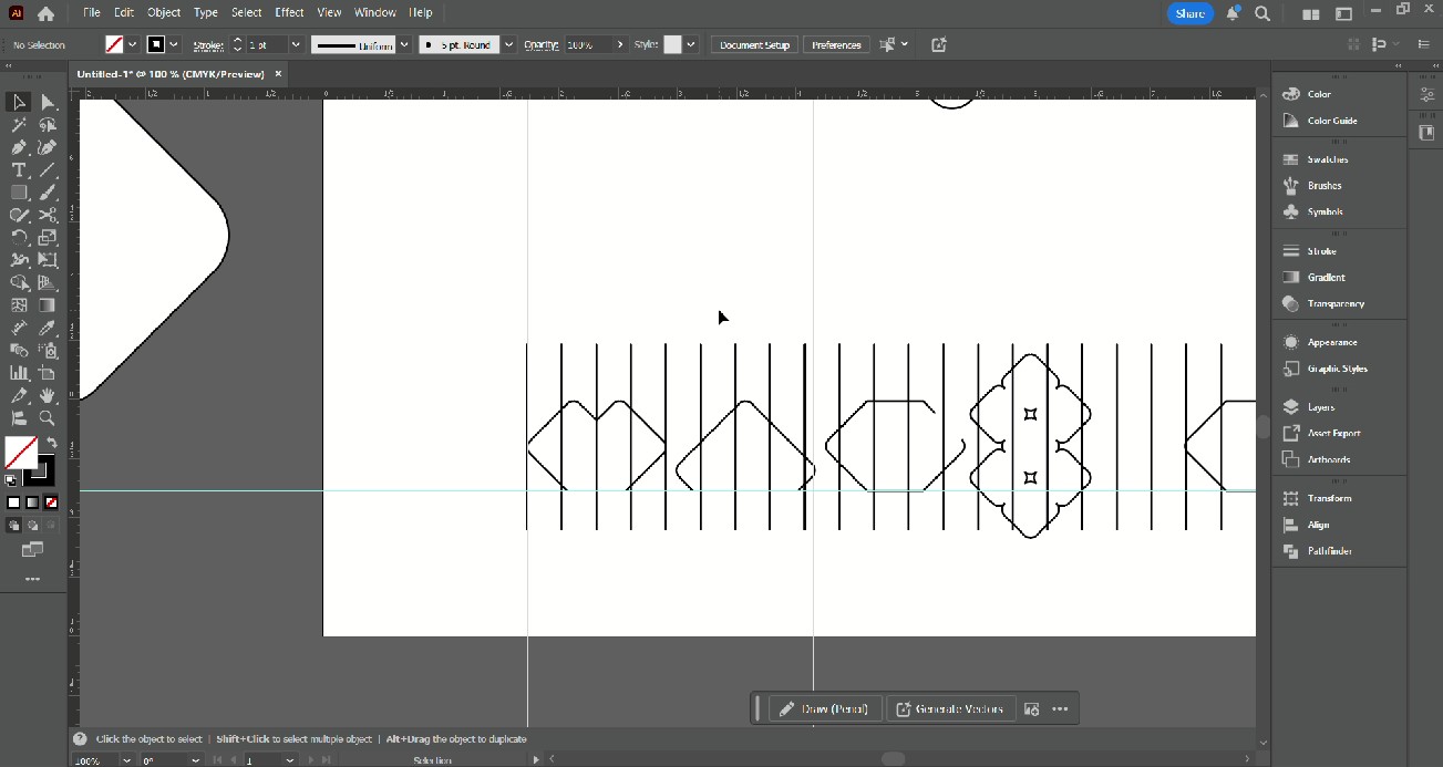
Nest I had to layout my elements. I tried adding the '8' in place of an 'I' for Magic. I then used evenly spaced vertical lines to maintain the proportions of the elements.
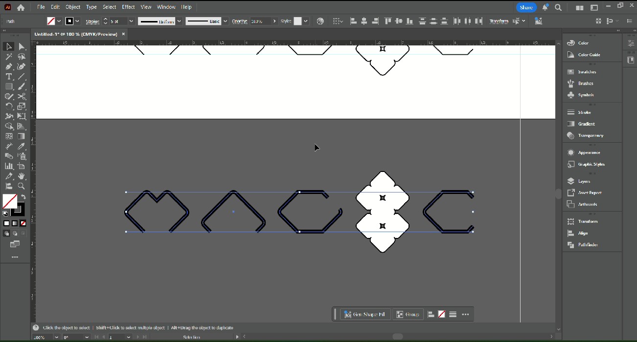
I copied the logo to test different variations. By changing the stroke thickness, I was able to make the text more bold and feel more prominent.
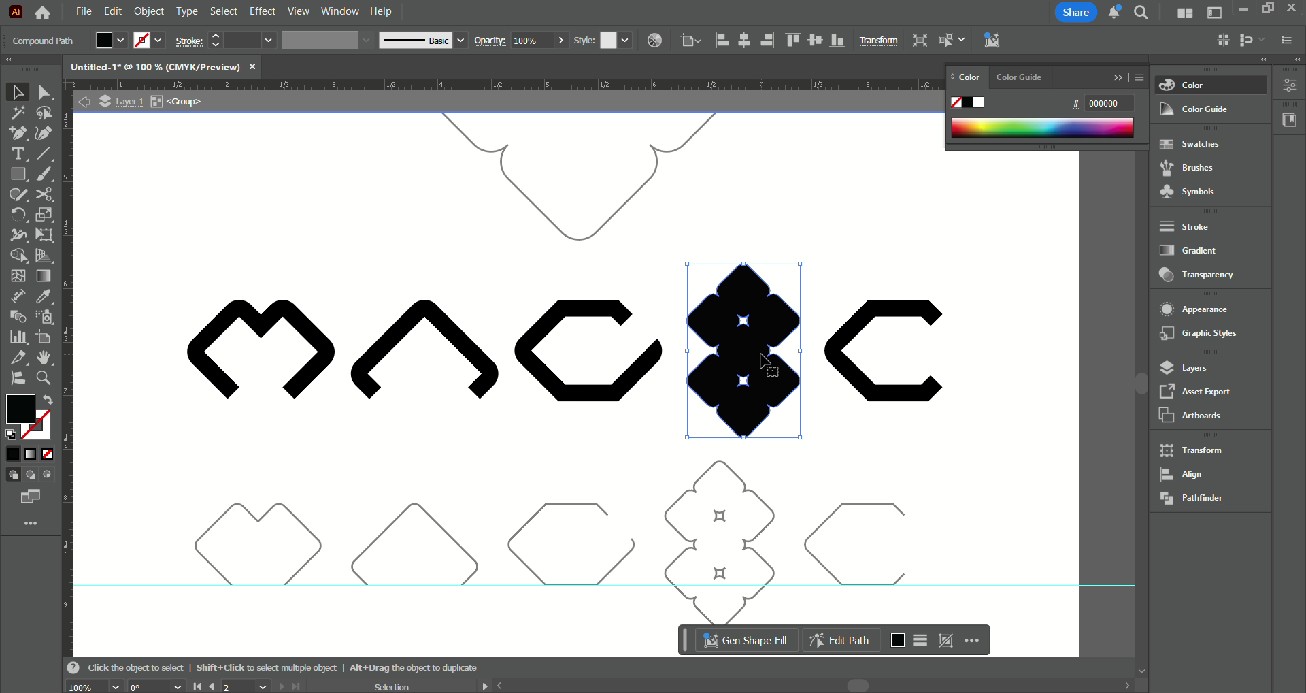
I also changed the '8' fill to black to increse the visual weight.
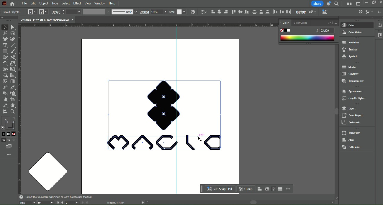
The final steps were to move the '8' to be centered above the text and create an 'I'. This became a variation of the original design, however, I think I prefer how it was before.
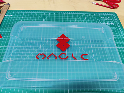
Vinyl Cutter
Materials
| Qty | Description | Price | Link |
|---|---|---|---|
| 1 | RGBW LEDS | $20.99 | LED |
| 1 | Seeed Xiao ESP32C3 | $9.99 | Xiao ESP32C3 |
| 1 | LED Matrix | $12.99 | Matrix |
| 1 | USB-C Cables | $9.99 | USB-C Cables |
| 1 | Keyboard switches | $27.90 | Keyboard switches |
| 1 | USB-C Power Supply | $12.99 | Power Supply |
| 1 | Surface Mounted Diodes | $7.99 | SMD |
| 1 | PLA Matte Filament | $10.99 | Filament |
| 1 | Milky White 1/8" Acrylic Sheets | $17.99 | Acrylic |
| 1 | Antenna | $9.99 | Antenna |
| 1 | 18 Gauge Wire | $23.75 | Wire |
| 1 | Hex Screws | $21.99 | Screw |
| 1 | 12"x12" Basswood 1/8" Sheets | $37.99 | Wood |
| 1 | Threaded inserts | $8.99 | Threaded inserts |
Project Plan View full details →
Task list and timeline for the Magic 8 project.
| # | Title | Description | Status | Start Date | End Date |
|---|---|---|---|---|---|
| 1 | Define Idea and Intent | Ideate project ideas that would be beneficial to educational programs at Moonlighter FabLab | Complete | Jan 21, 2026 | Jan 28, 2026 |
| 2 | Initial Concept Development | Start sketching ideas of the project and possible ways of producing it | Complete | Jan 21, 2026 | Jan 28, 2026 |
| 3 | Phase 1 Research | Look up existing examples of similar devices and how they are made | Complete | Jan 28, 2026 | Feb 4, 2026 |
| 4 | Sketch Model | Using Rhino 8, design a 3D model of the concept | Complete | Jan 28, 2026 | Feb 4, 2026 |
| 5 | 3D Rendering | Using Twinmotion, create a video render of the concept model | Complete | Feb 4, 2026 | Feb 11, 2026 |
| 6 | Logo Design | Design a logo of the product name and make a vinyl sticker | Complete | Feb 4, 2026 | Feb 11, 2026 |
| 7 | Phase 2 Research | Look at new examples based on updated knowledge and skills | Complete | Feb 11, 2026 | Feb 18, 2026 |
| 8 | Revised Concept Development | Update the concept based on revised information | Complete | Feb 11, 2026 | Feb 18, 2026 |
| 9 | Test LED Matrix and Embedded Program | Test major component to ensure effectiveness | Complete | Feb 11, 2026 | Feb 18, 2026 |
| 10 | Test Webapp Interface | Vibe code a webapp to understand limitations and how to integrate | Complete | Mar 18, 2026 | Apr 8, 2026 |
| 11 | Wifi Protocols and Web Interface | Select and program microcontrollers for wifi connectivity | Complete | Mar 18, 2026 | Apr 8, 2026 |
| 12 | PCB Design and Milling | Produce a PCB to integrate test components | Complete | Mar 18, 2026 | Apr 8, 2026 |
| 13 | Phase 2 Test Matrix Complete | Ensure that hardware and software are operational | Complete | Mar 18, 2026 | Apr 8, 2026 |
| 14 | Phase 3 Design 3D Modeling | Using Rhino 8, design and plan the layout of the hardware components | Complete | Apr 8, 2026 | Apr 15, 2026 |
| 15 | Order Components and Materials | Source and order all necessary components with adequate delivery time | Complete | Apr 8, 2026 | Apr 15, 2026 |
| 16 | Design and Mill Final PCBs | Produce all final PCBs | Complete | Apr 8, 2026 | Apr 15, 2026 |
| 17 | Solder PCBs | Solder switch PCBs and microcontroller PCB components | Not Started | May 6, 2026 | May 13, 2026 |
| 18 | Laser Cut Internal Layers | Send internal layer files to be laser cut | In Progress | May 6, 2026 | May 13, 2026 |
| 19 | 3D Print Base Enclosure | Prepare, slice and print 3D print files | In Progress | May 6, 2026 | May 13, 2026 |
| 20 | Assemble Base Components | Clean, assemble and glue base components | In Progress | May 6, 2026 | May 13, 2026 |
| 21 | Install PCBs and Wiring | Lay wiring and install PCBs | In Progress | May 6, 2026 | May 13, 2026 |
| 22 | 3D Print Top Components | Prepare, slice and print 3D print files | In Progress | May 6, 2026 | May 13, 2026 |
| 23 | Laser Cut Tiles and Matrix Diffuser | Send top components to be laser cut from acrylic | Not Started | May 6, 2026 | May 13, 2026 |
| 24 | Install LEDs | Connect switch caps, wire and solder LEDs | Not Started | May 13, 2026 | May 20, 2026 |
| 25 | Phase 4 Vibe Code Web Interface | Using Claude.ai, generate the code for the web interface | Not Started | May 13, 2026 | May 20, 2026 |
| 26 | Troubleshoot | Test and resolve issues as they arise | Not Started | May 13, 2026 | May 20, 2026 |
| 27 | Complete Assembly | Close the enclosure and connect the device | Not Started | May 13, 2026 | May 20, 2026 |
| 28 | Complete Applications and Implications, Project Development | Answer the questions and update the website | Not Started | May 20, 2026 | May 27, 2026 |
| 29 | Complete Invention, Intellectual Property and Income | Answer the questions and update the website | Not Started | May 20, 2026 | May 27, 2026 |
| 30 | Create a Video Presentation | Compile a video of the project design and fabrication process | Not Started | May 27, 2026 | Jun 8, 2026 |
| 31 | Create a Presentation Slide | Create a descriptive slide about the project | Not Started | May 27, 2026 | Jun 8, 2026 |
| 32 | Final Revisions and Submission | Complete outstanding documentation and updates | Not Started | Jun 8, 2026 | Jun 24, 2026 |
System Sketches
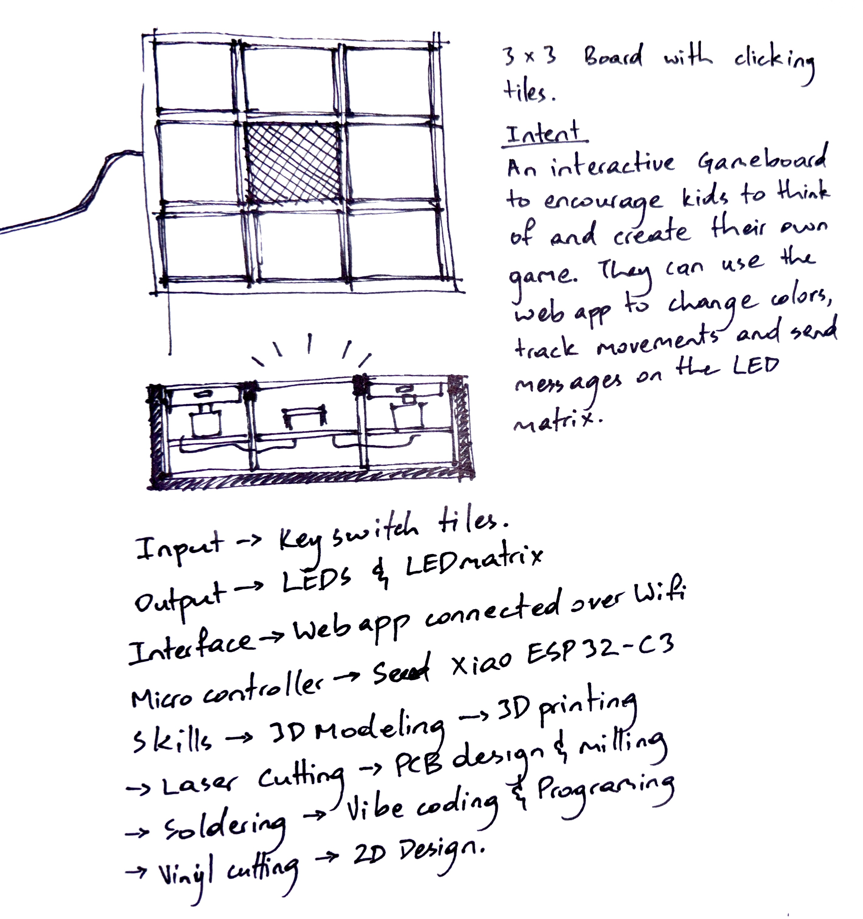

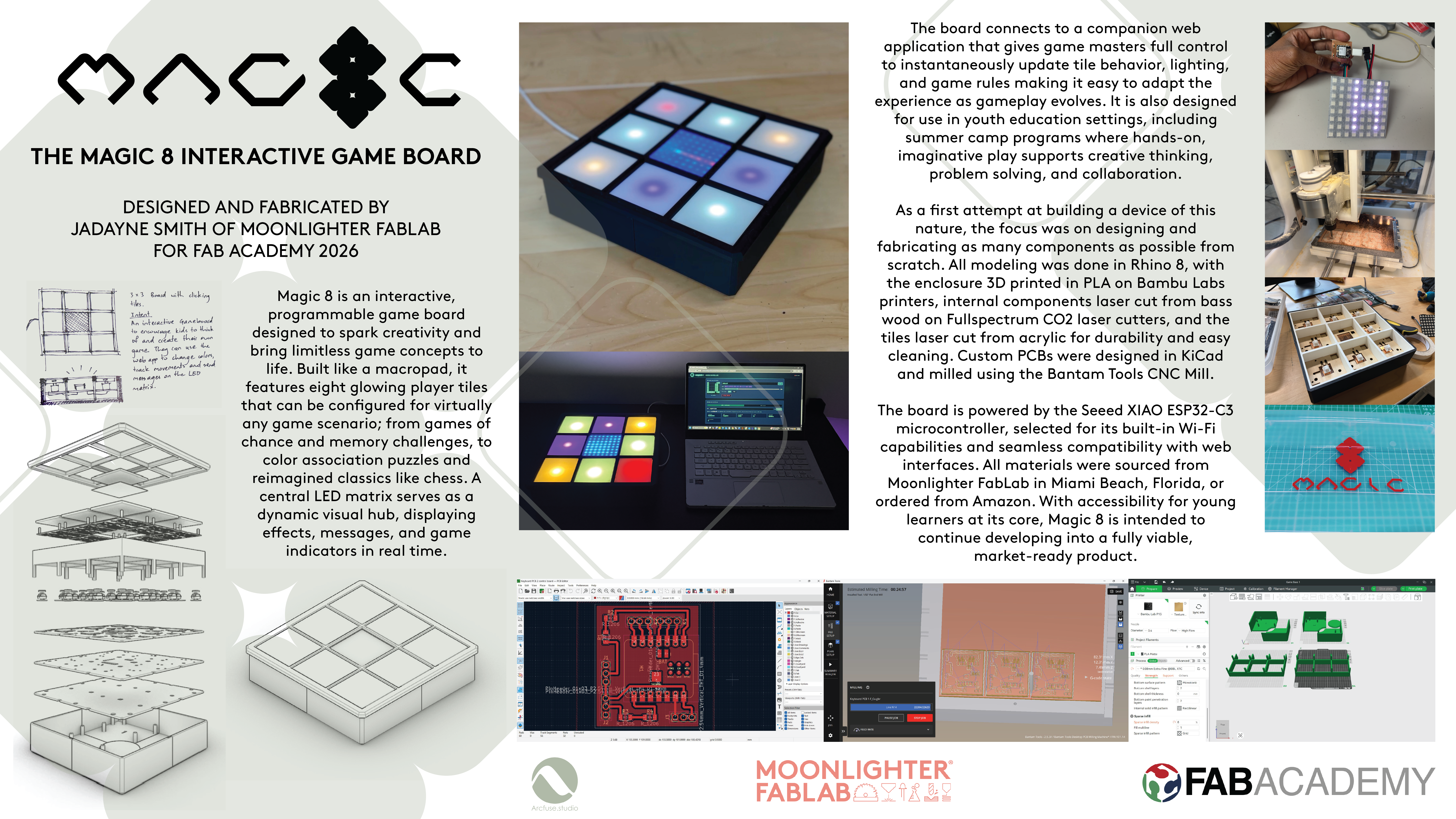
These sketches show how I was thinking aboutht the components and functions of the system. A 3x3 board with clickable inputs in the 8 outer squares, compartments for the inner components, a layer to organize the wiring, partition walls that offer structure and light isolation and a plan for how the physical form will influence the software functions.
System Diagrams
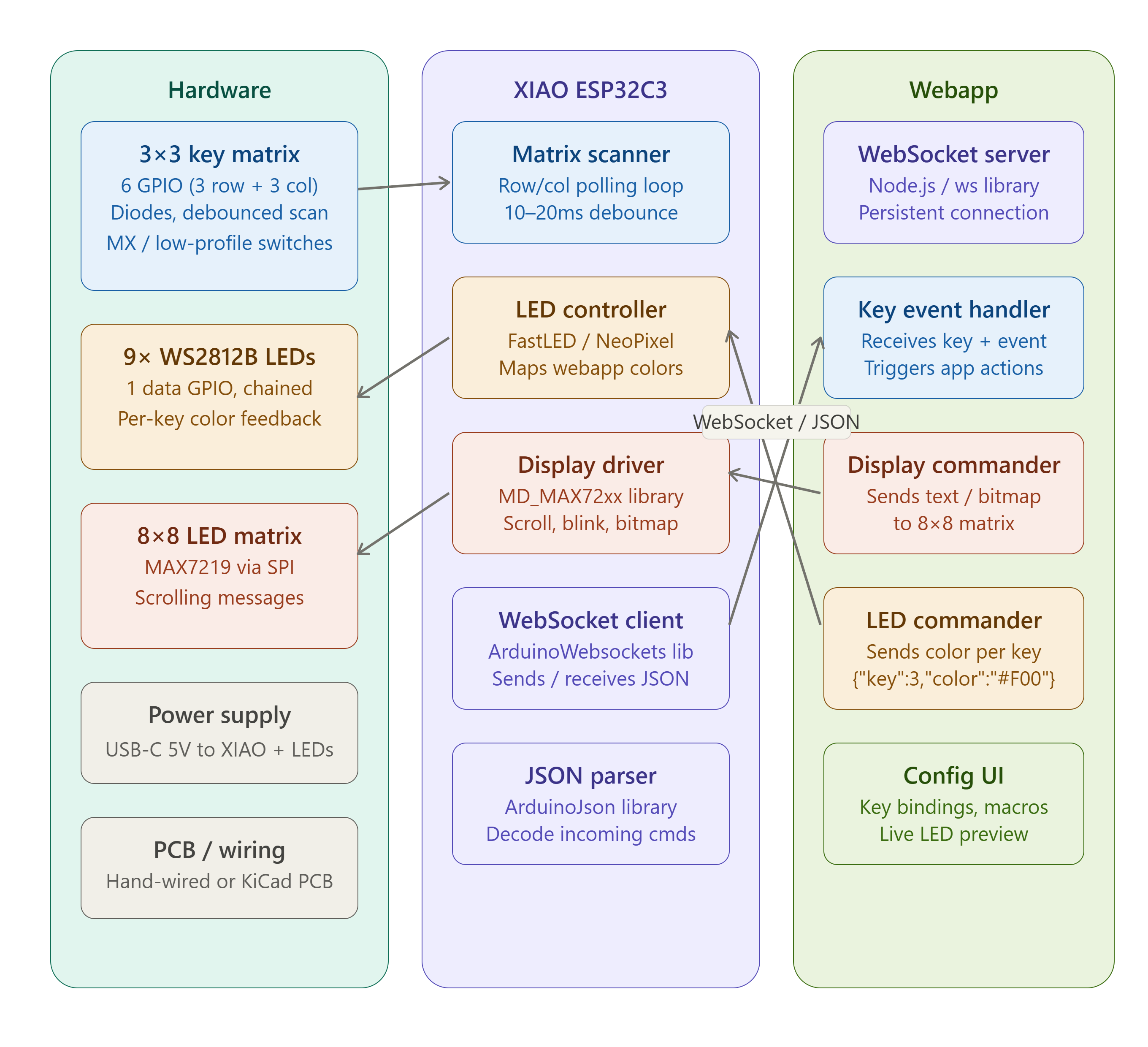
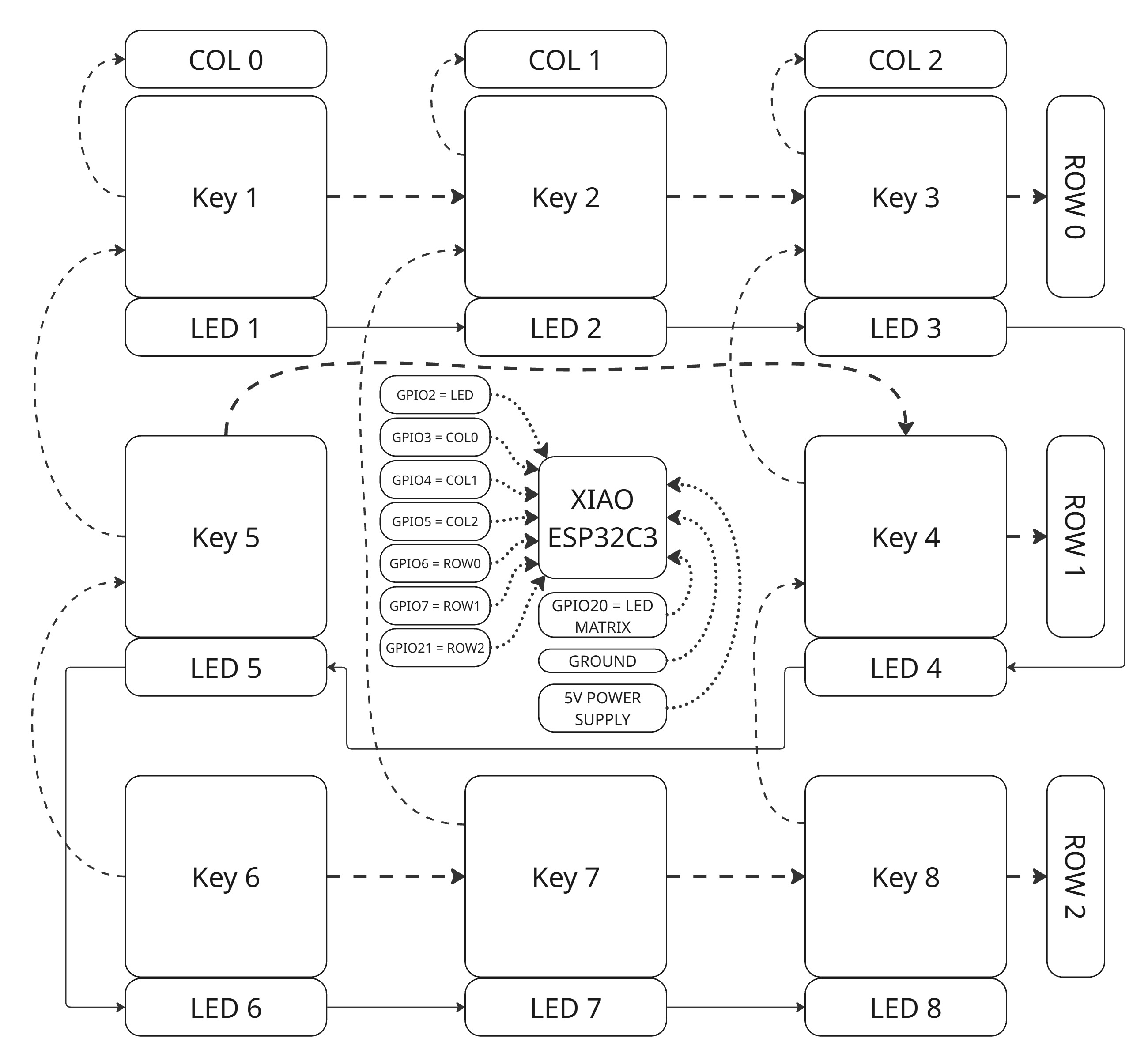
Layered Plan of the System Integration
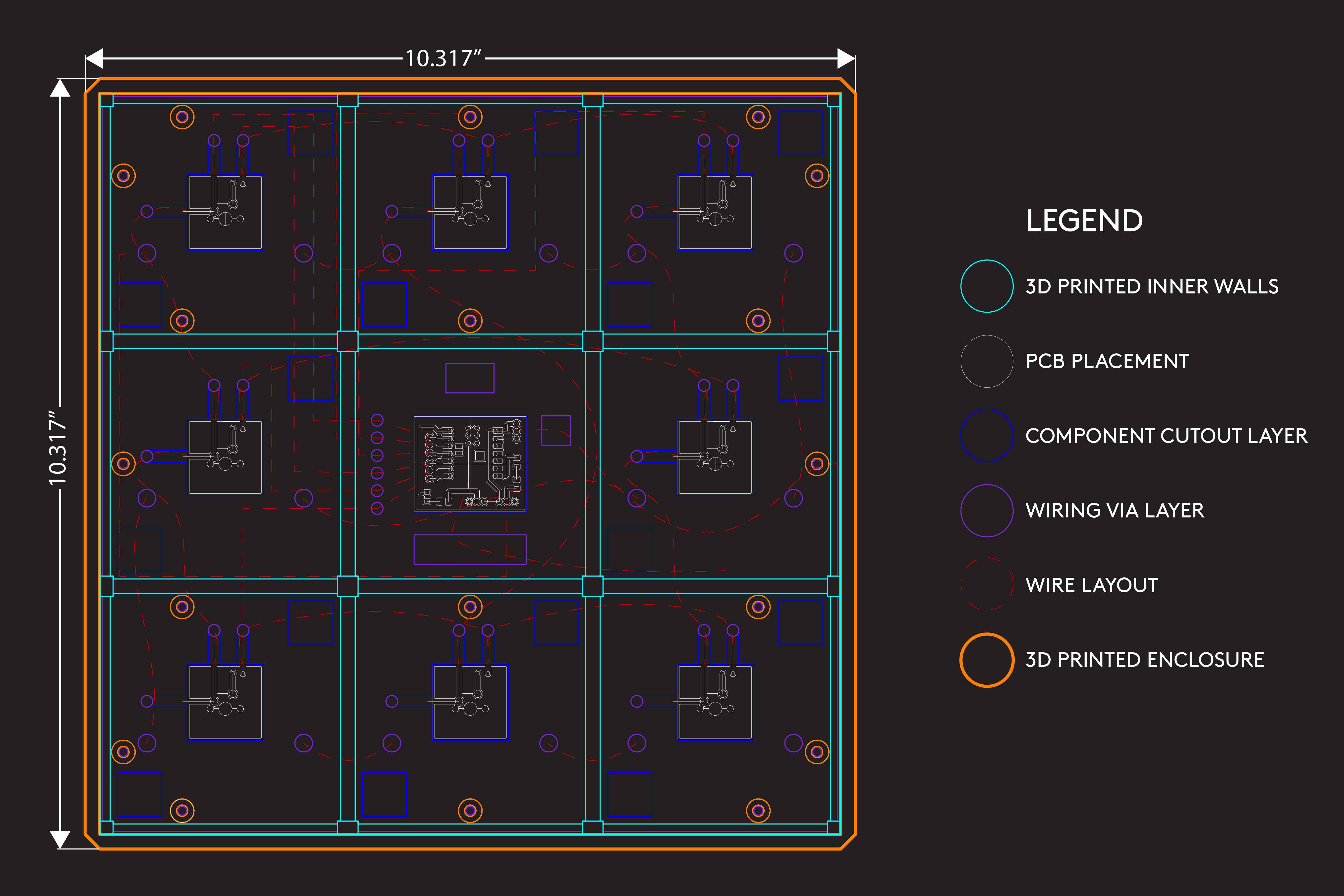
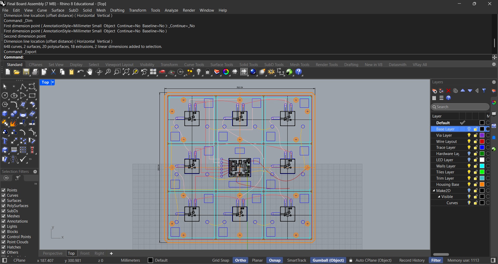
I used Rhino 8 to layout each layer of the project and how the components and wiring would be secured.
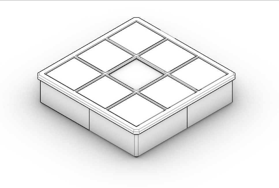
The layout was then turned into a 3D model which I could use to fabricate the physical components.
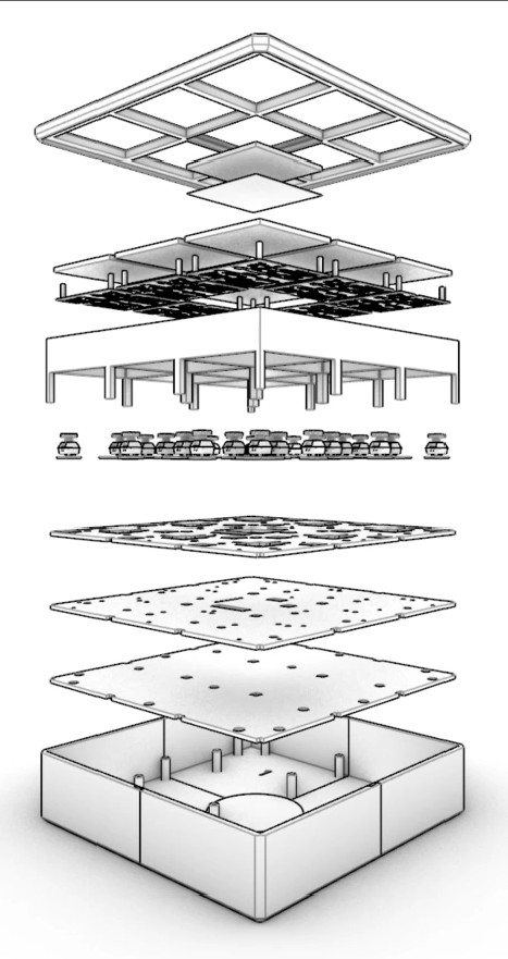
This exploded perspective view shows how each component aligns and works together to form a unified system. I relied heavily on my architectural background for this design.
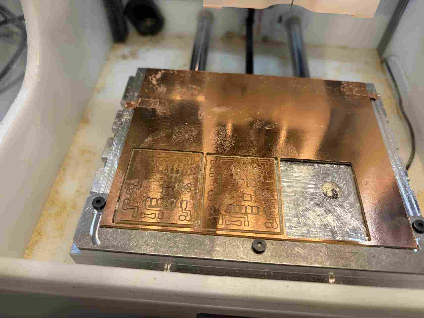
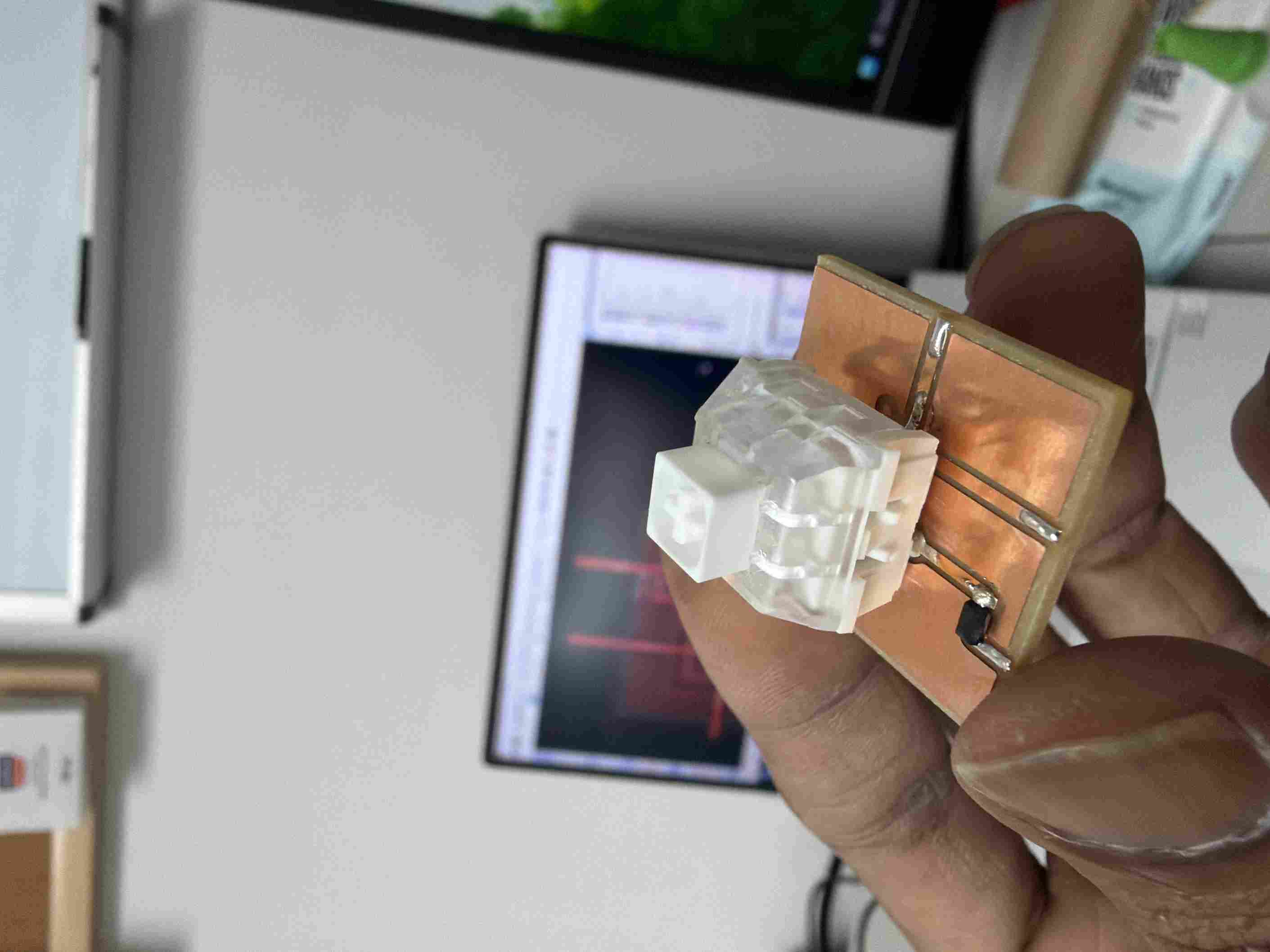
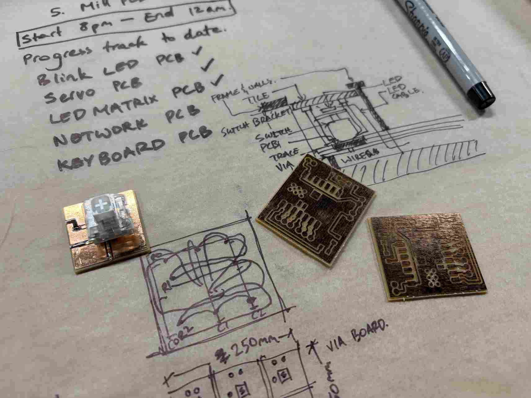
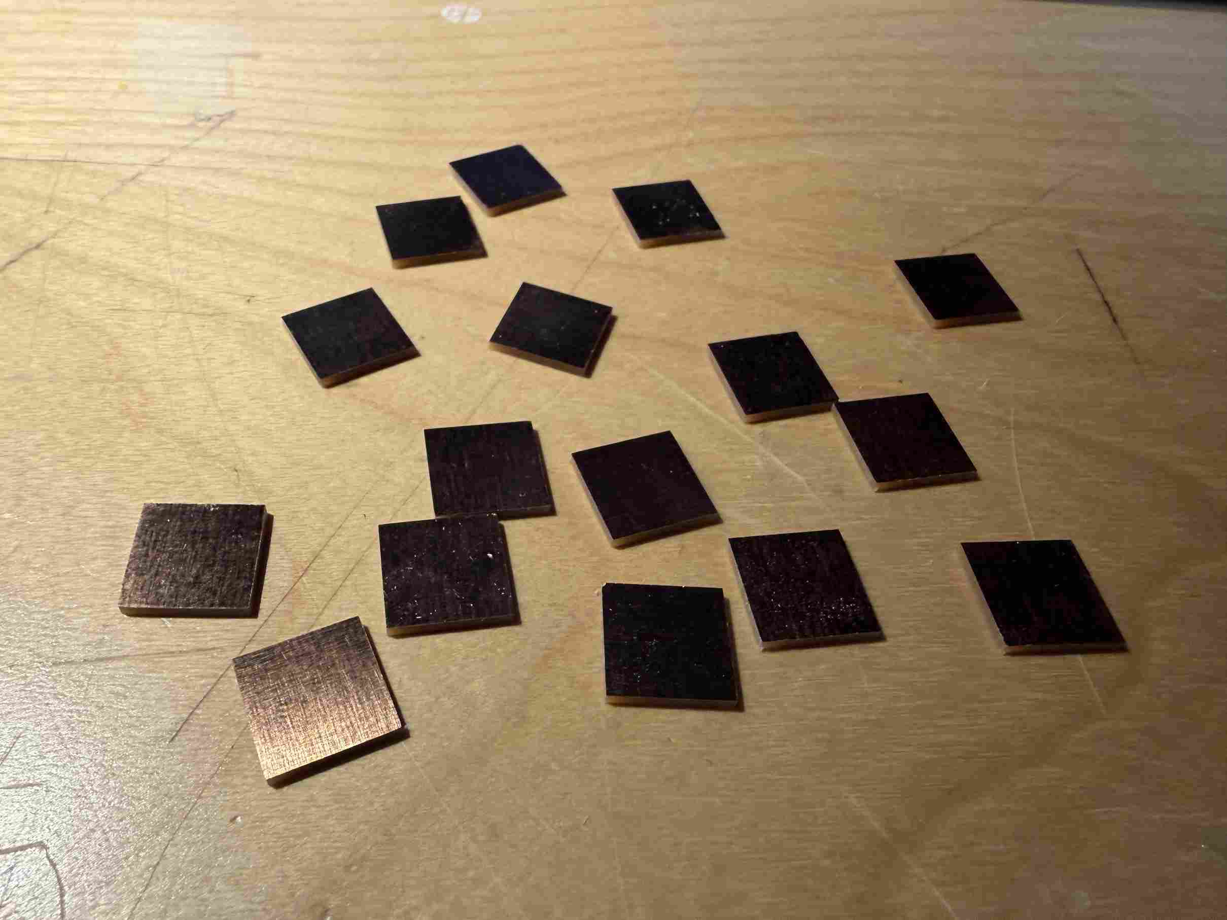
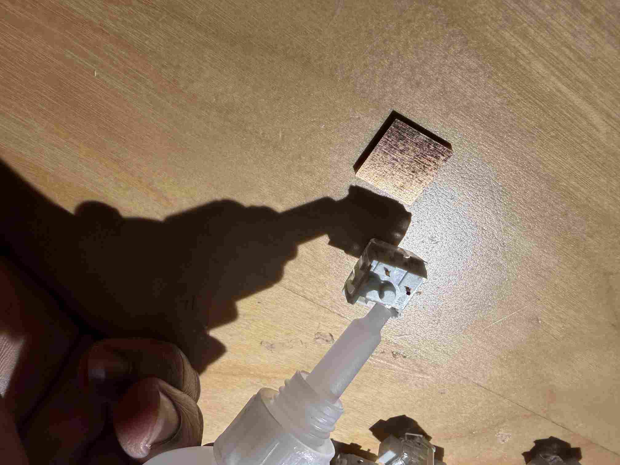
I designed and milled the PCB using the Bantam Tools CNC machine.The key switched were glued and soldered in place along with the diodes. The pins for the switches were clipped to an appropriate length to be surface mounted.
In this sketch, I was still working through the layout and wiring before the final design seen above.
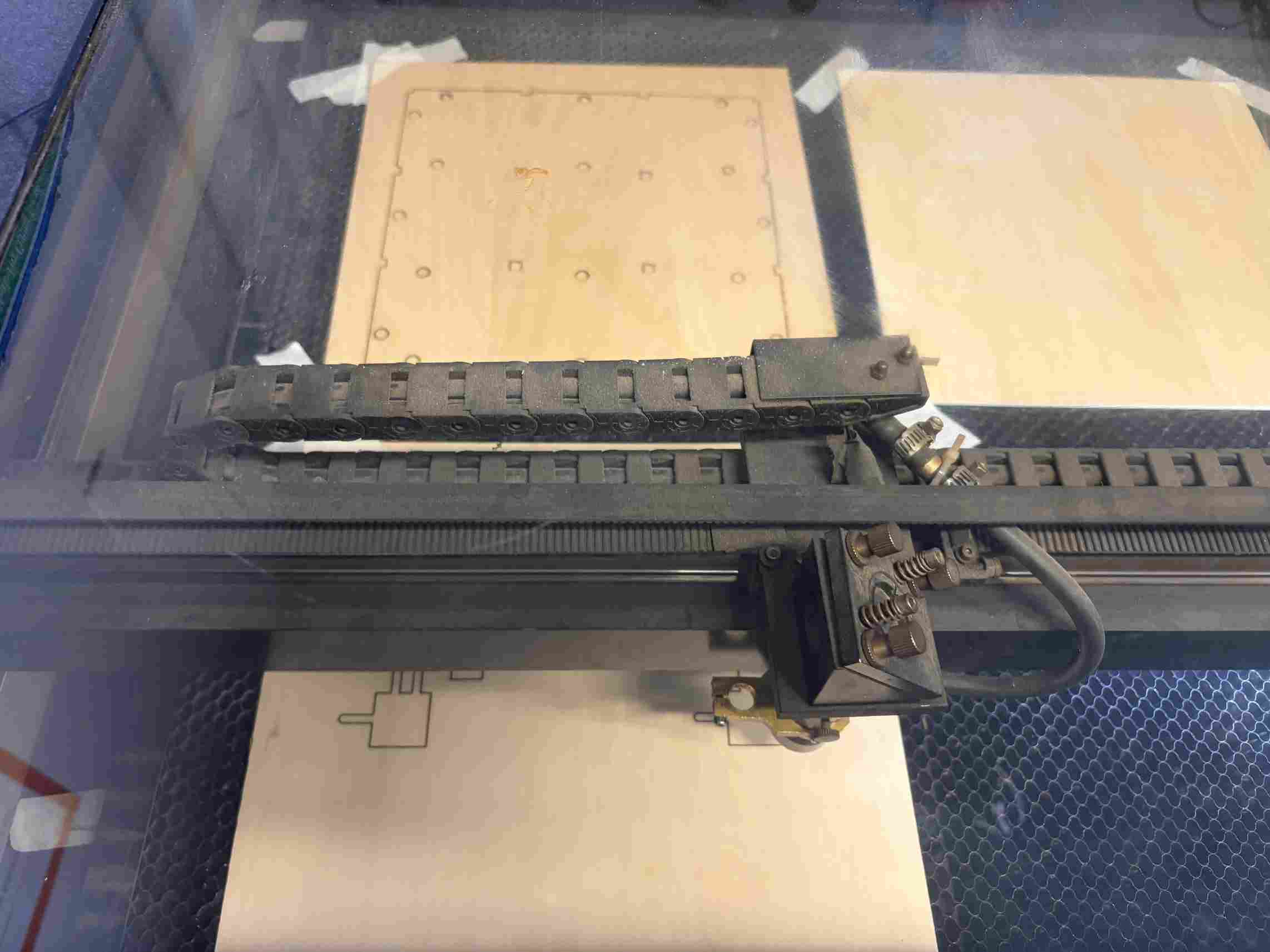
I laser cut the inner layers that align the base and support the other components. This was cut out of basswood.
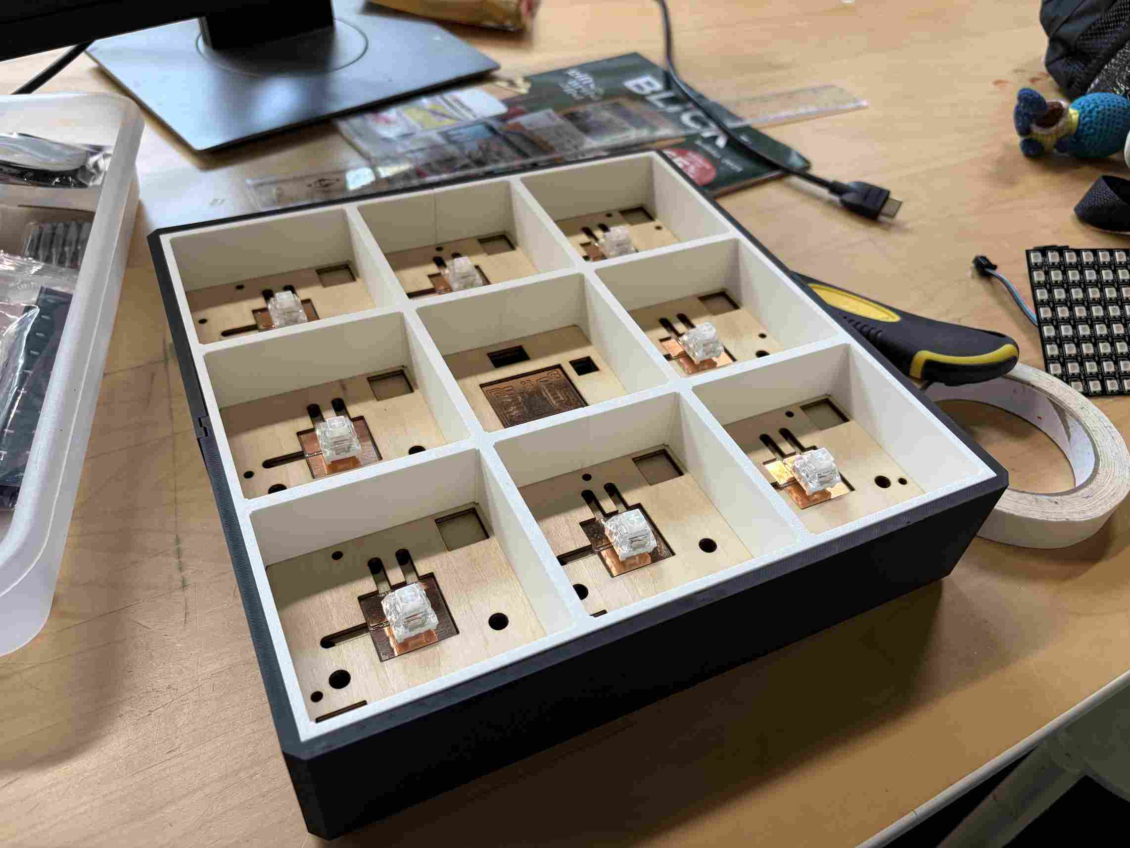
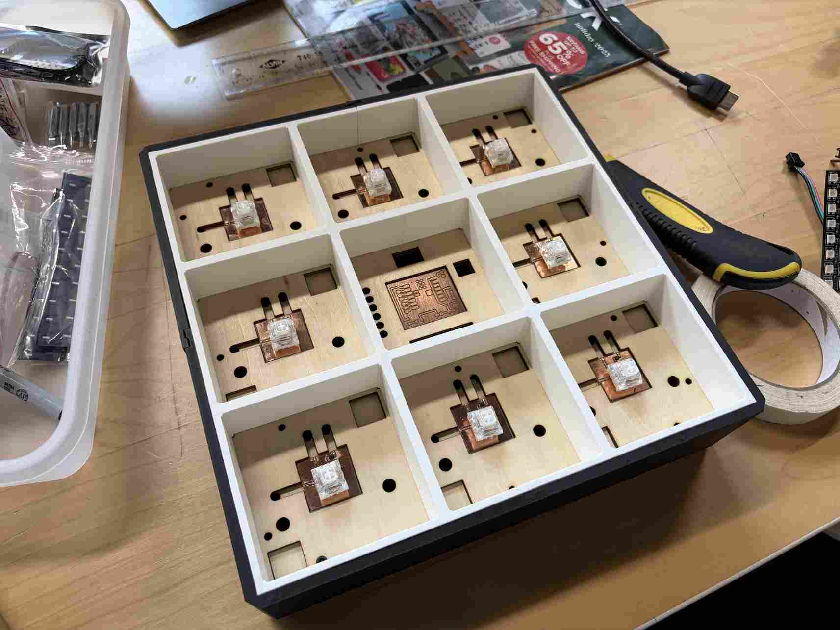
Dryfitting the parts to make sure they align properly before final assembly.
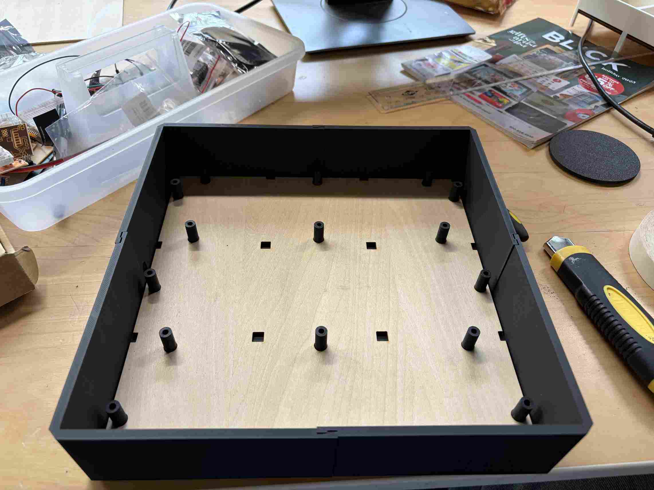
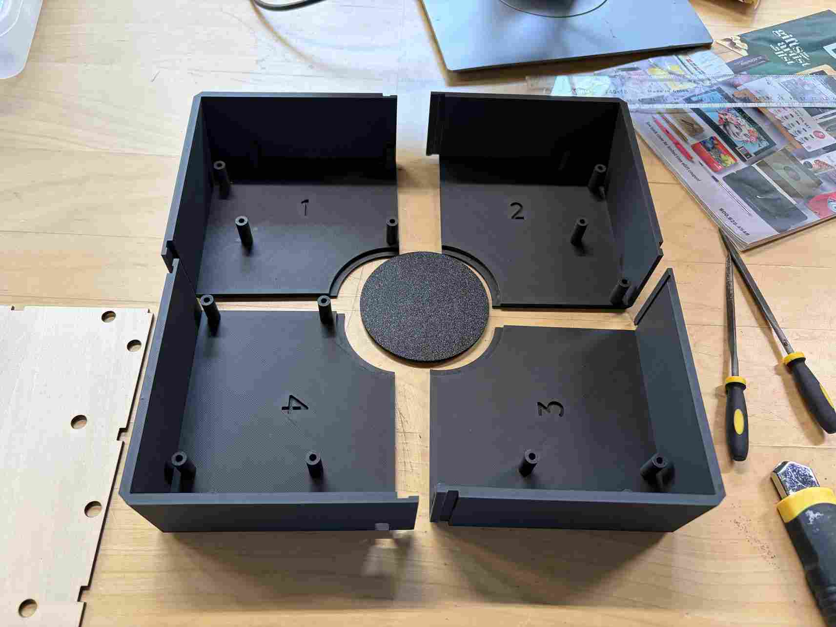
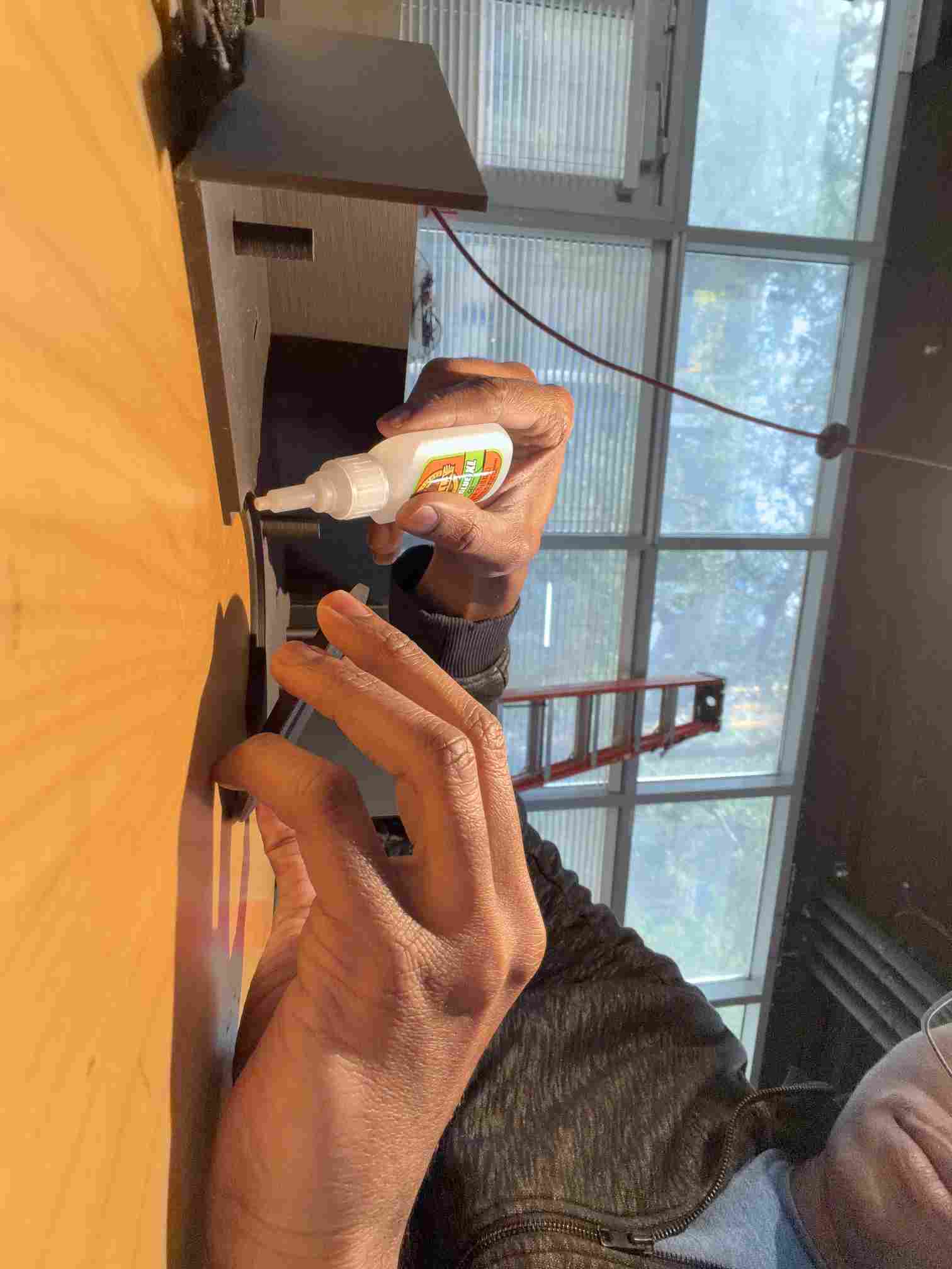
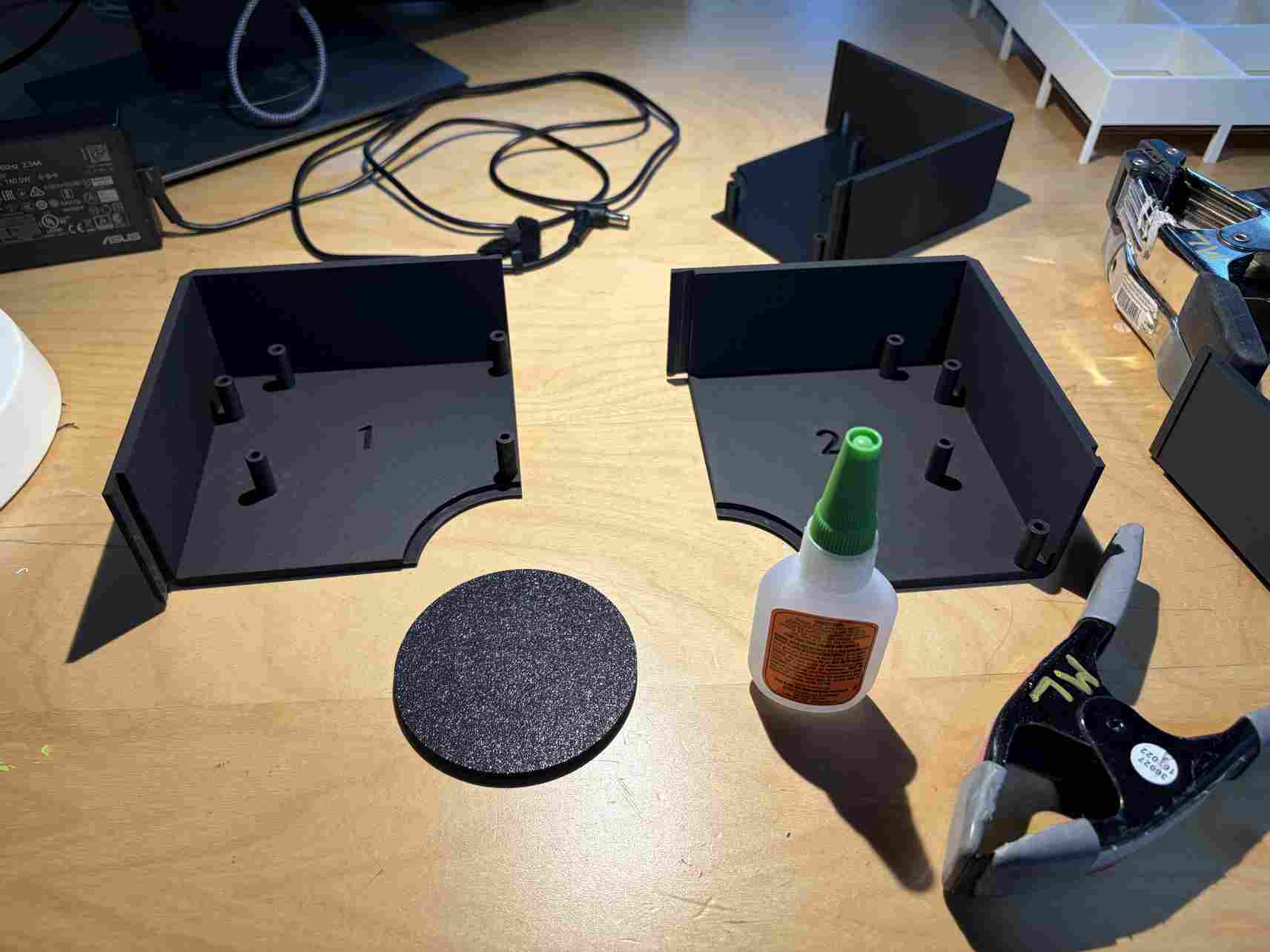
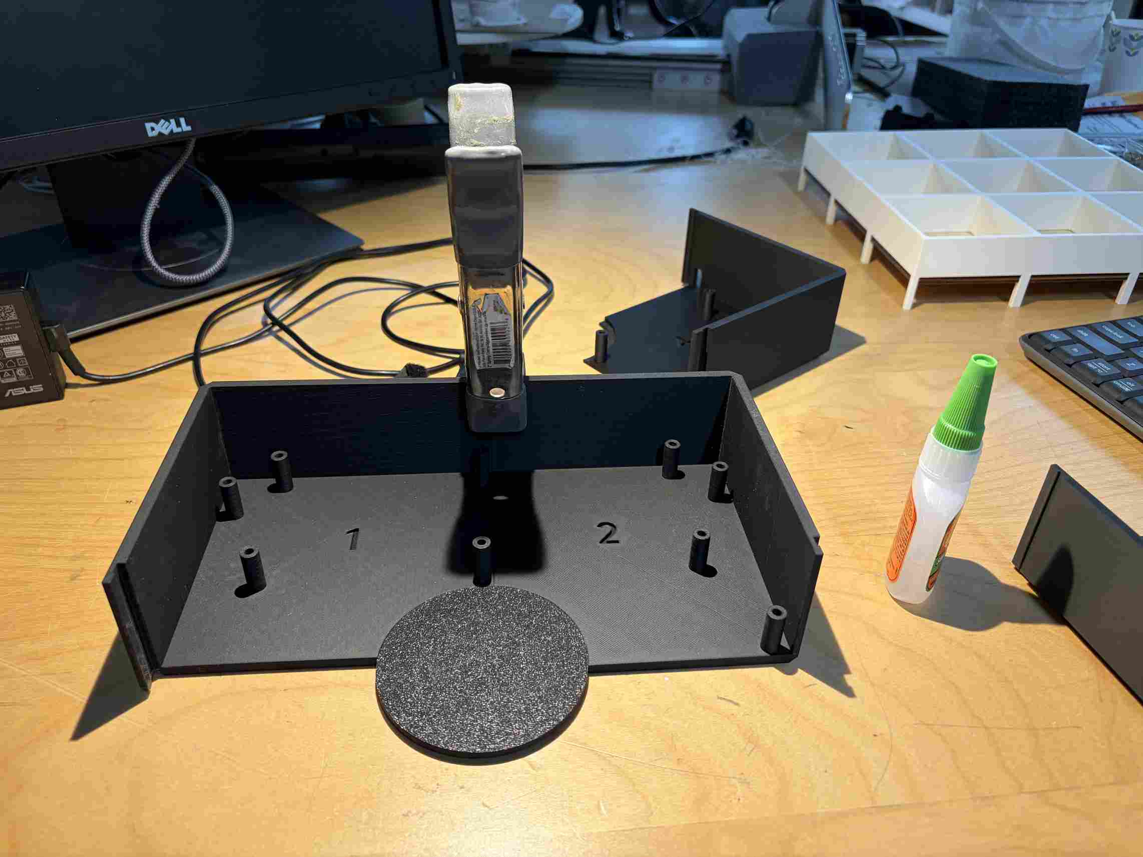
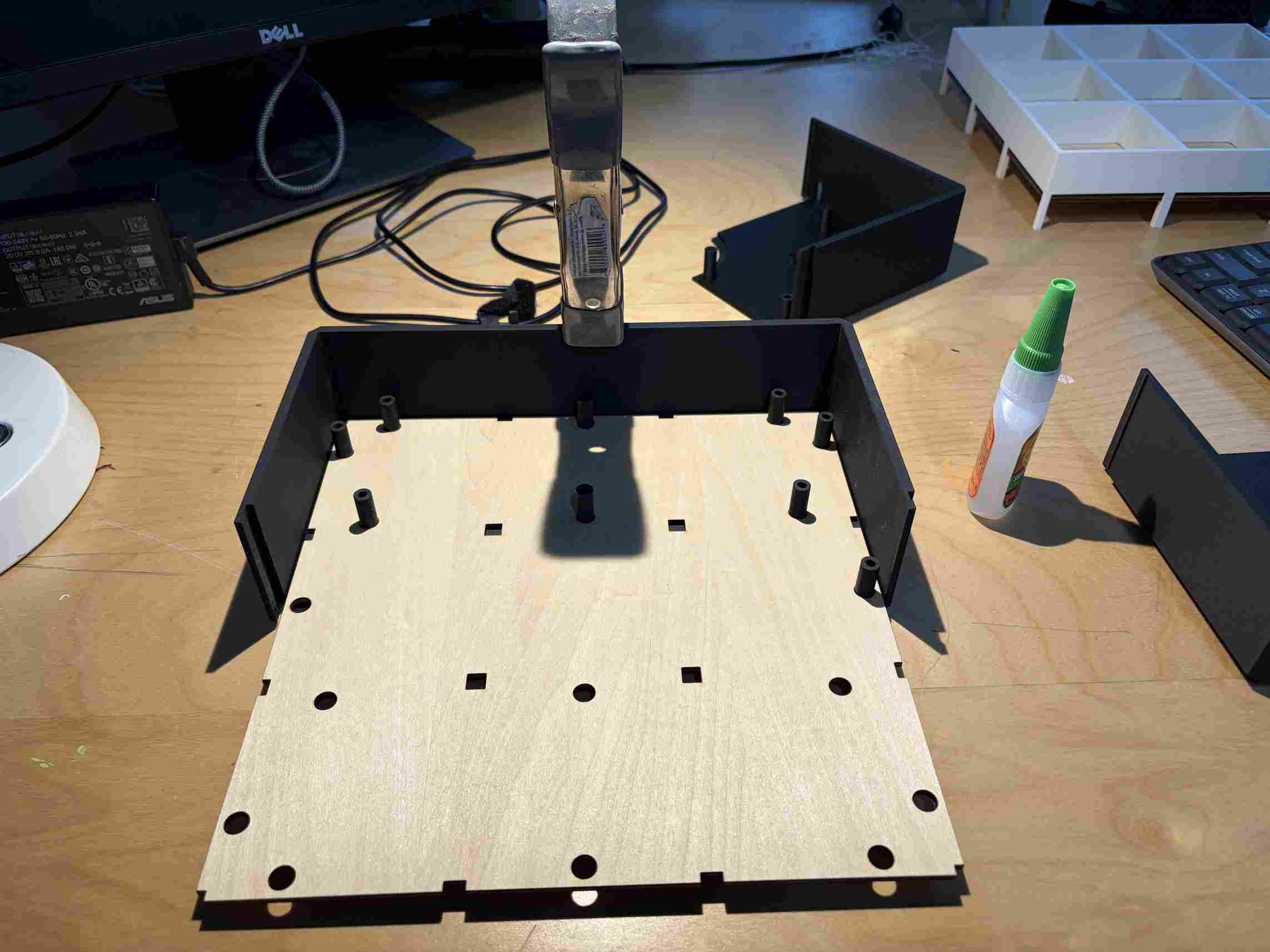
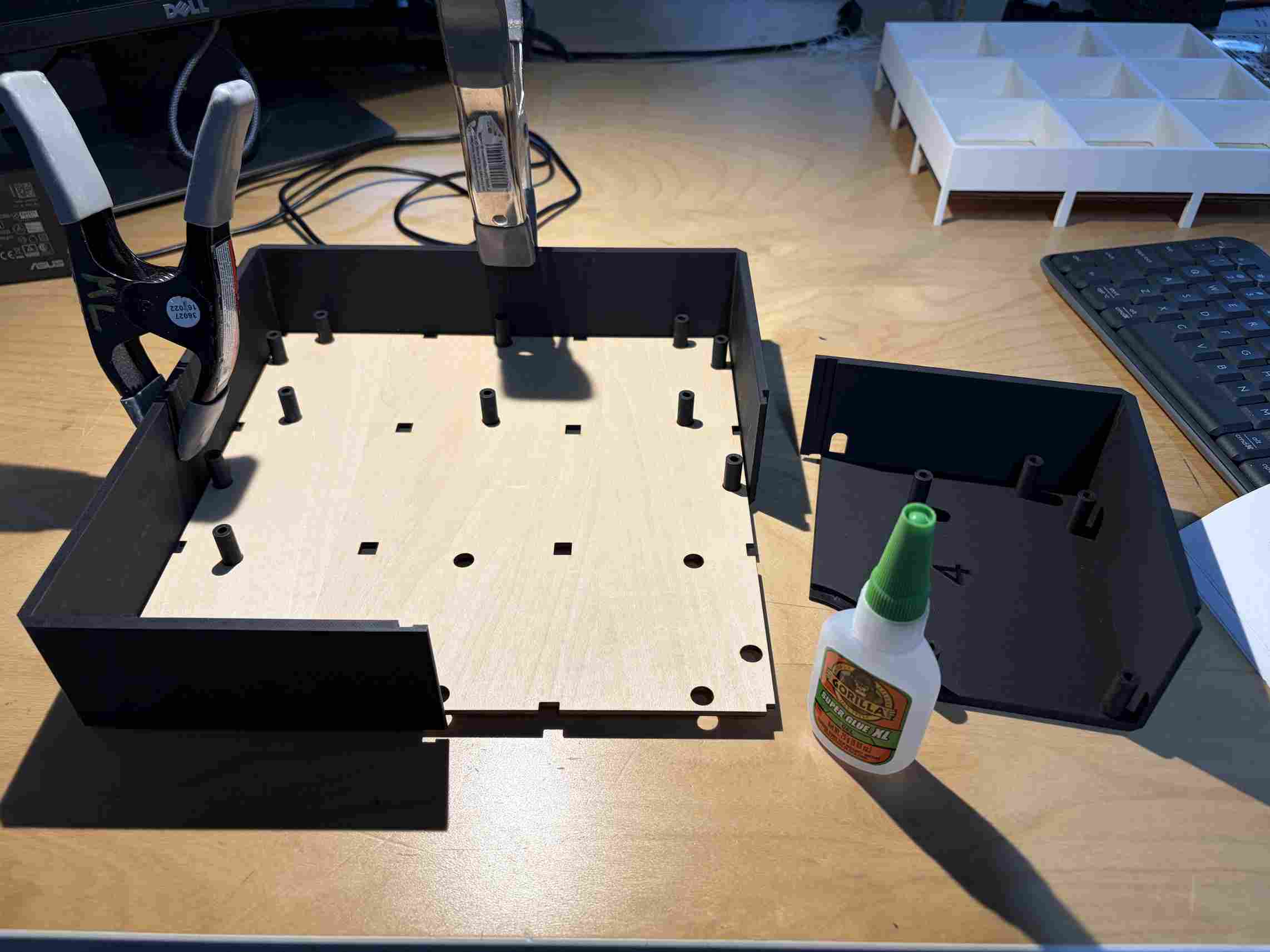
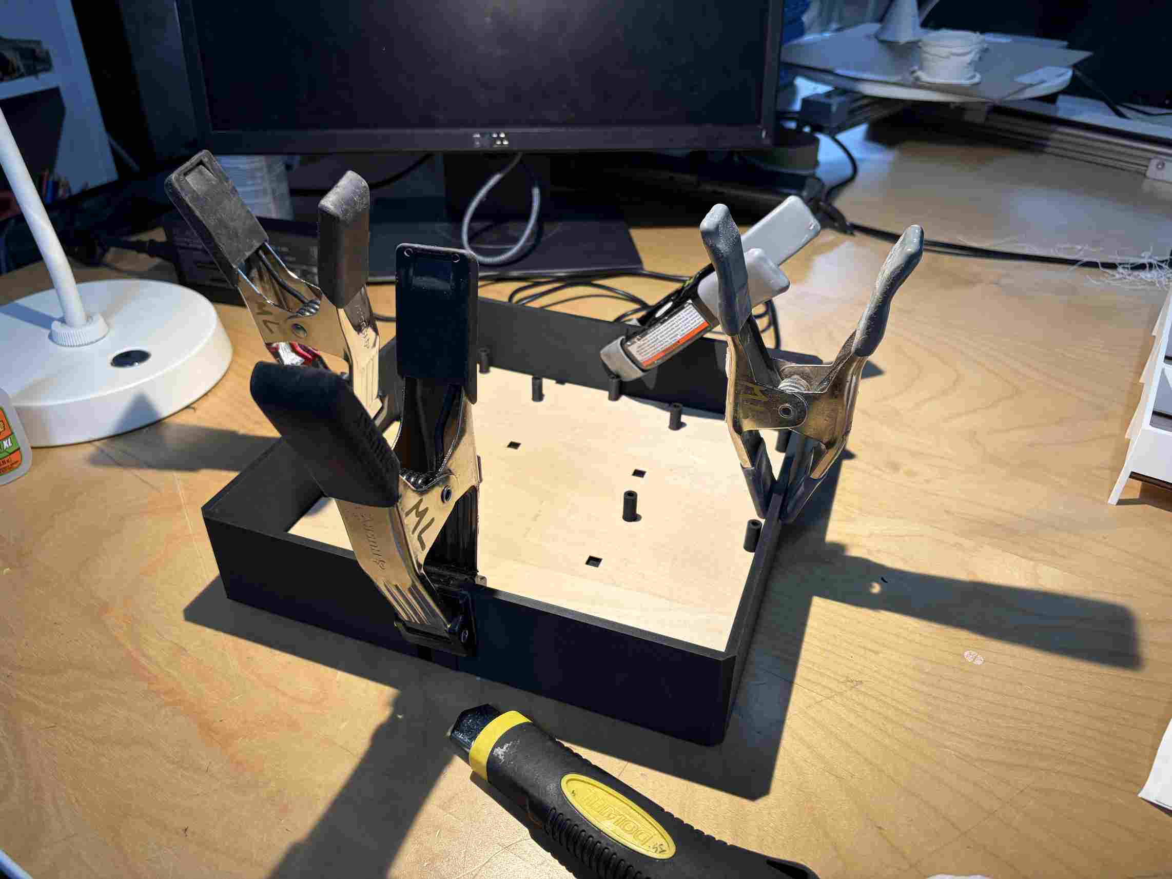
The parts came together like a puzzle but I was able to align them and used super glue for a fast and secure bond. The clamps applied pressure while the glue set.
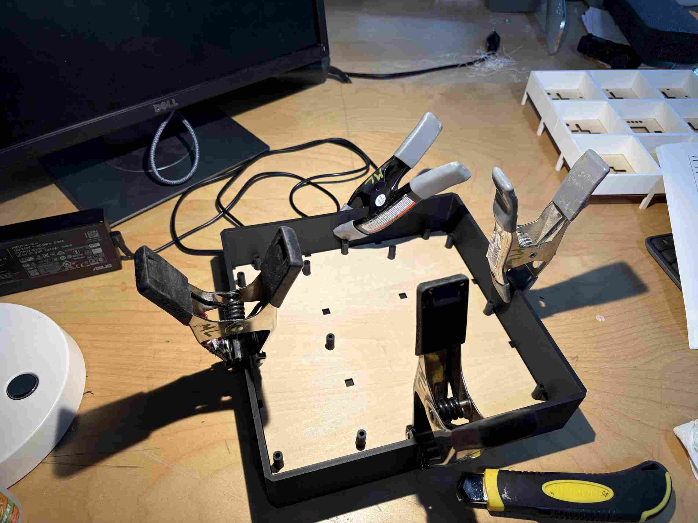
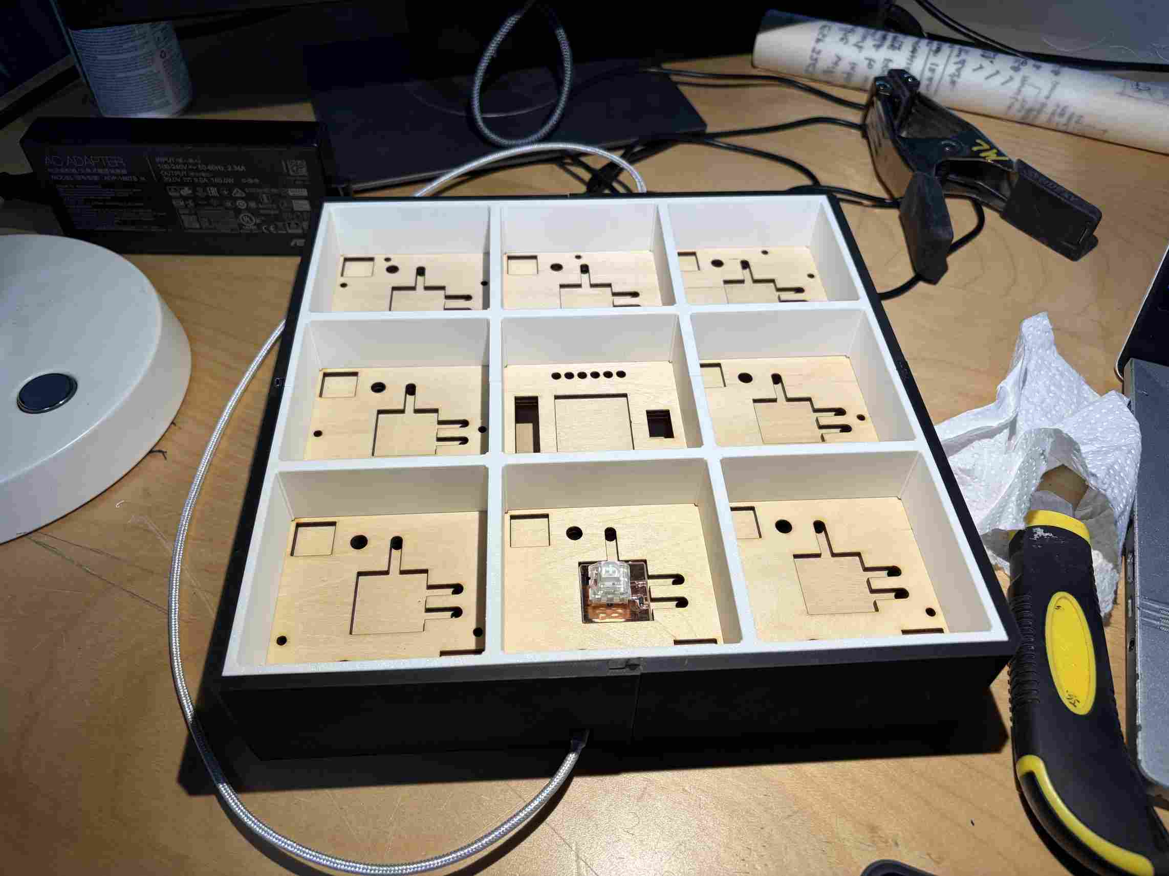
The assembly was so exact that it became very difficilt to remove the middle layers with the 3D printed walls and columns once in place. I however had to do so periodically to ensure that there were no misalignments with each step.
Each of the outer squares has 2 "dummy switches" to add stability to the player tiles. This improves durability and the game play experience.
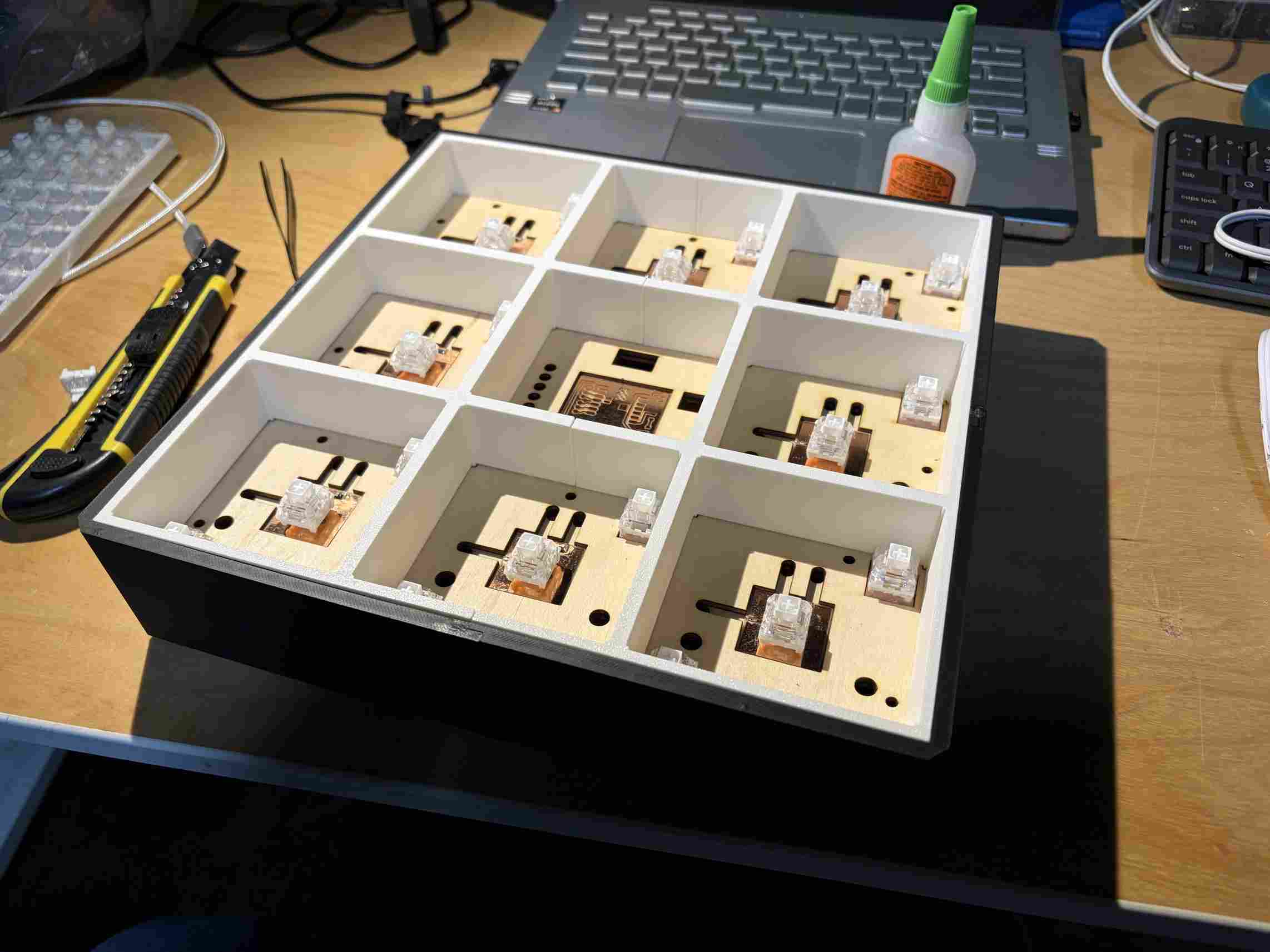
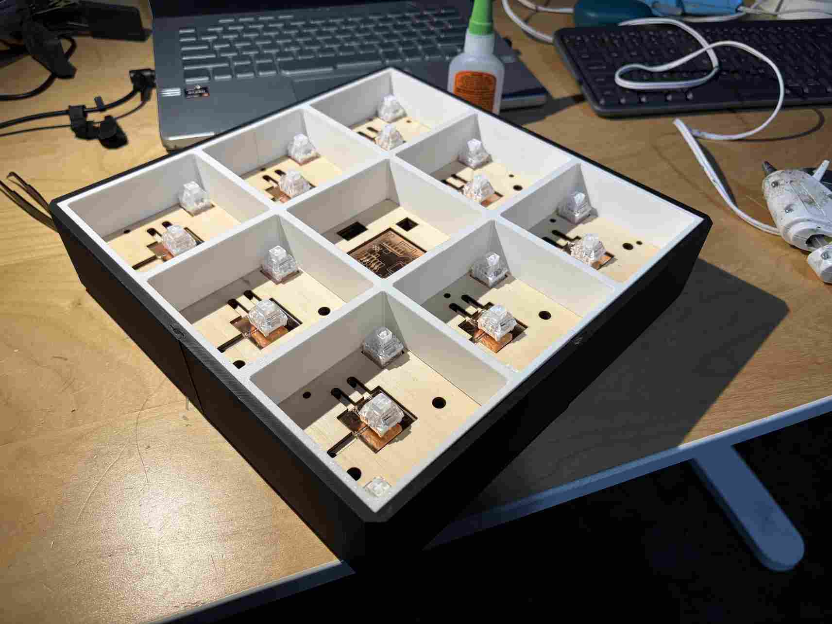
Everything in place.
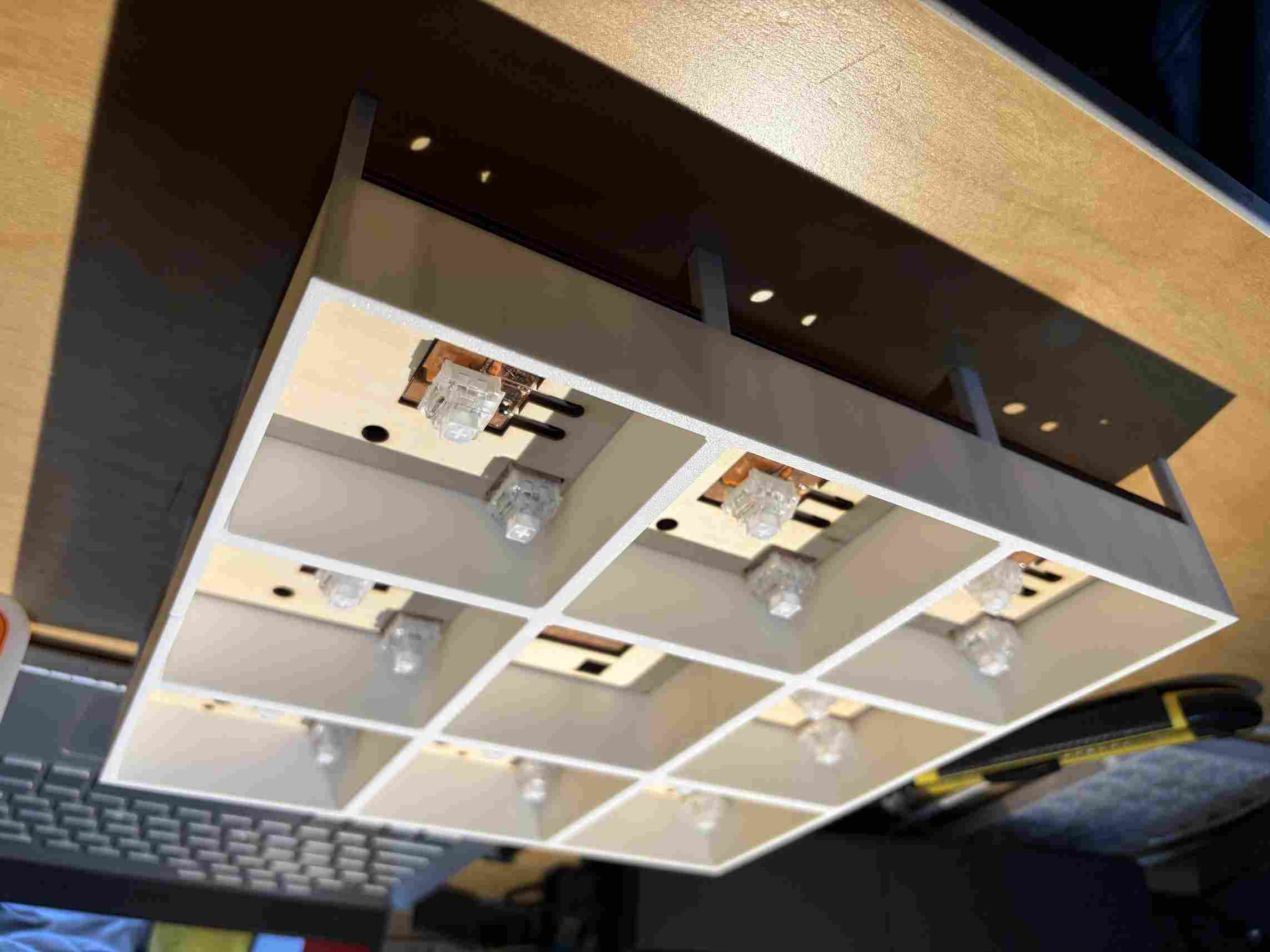
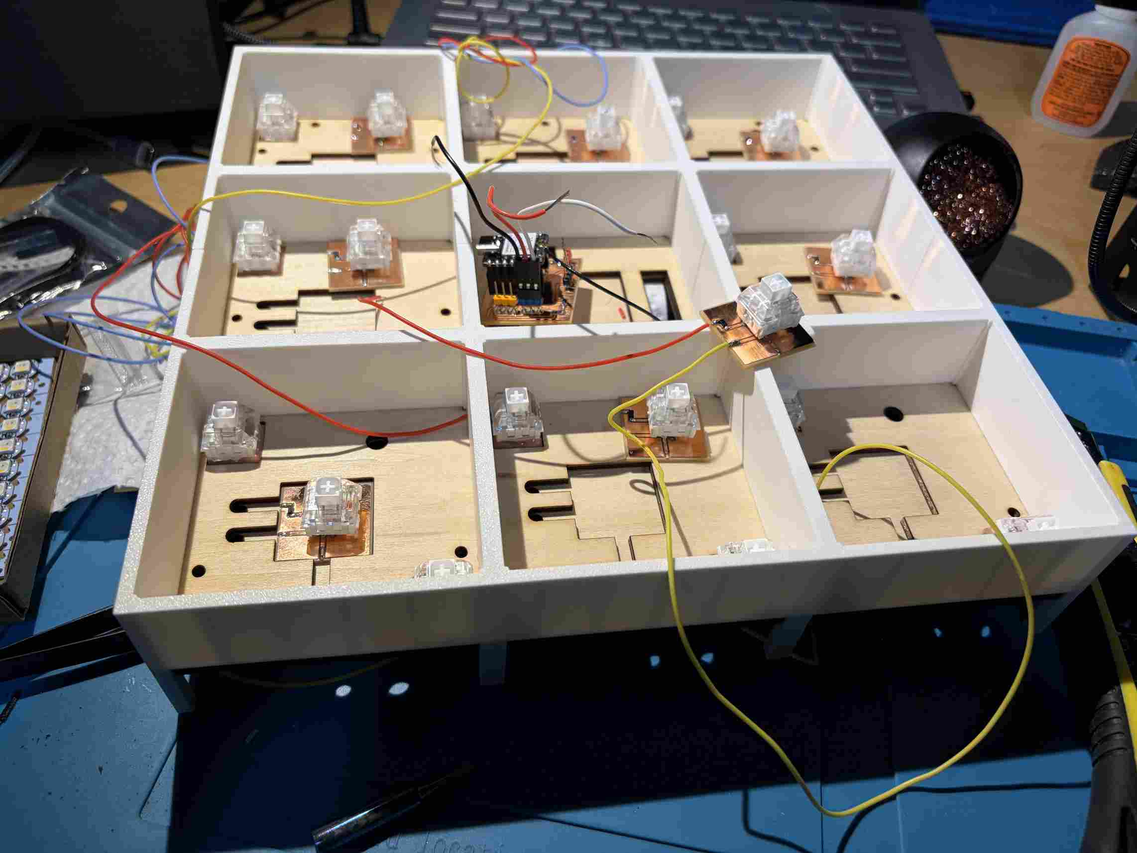
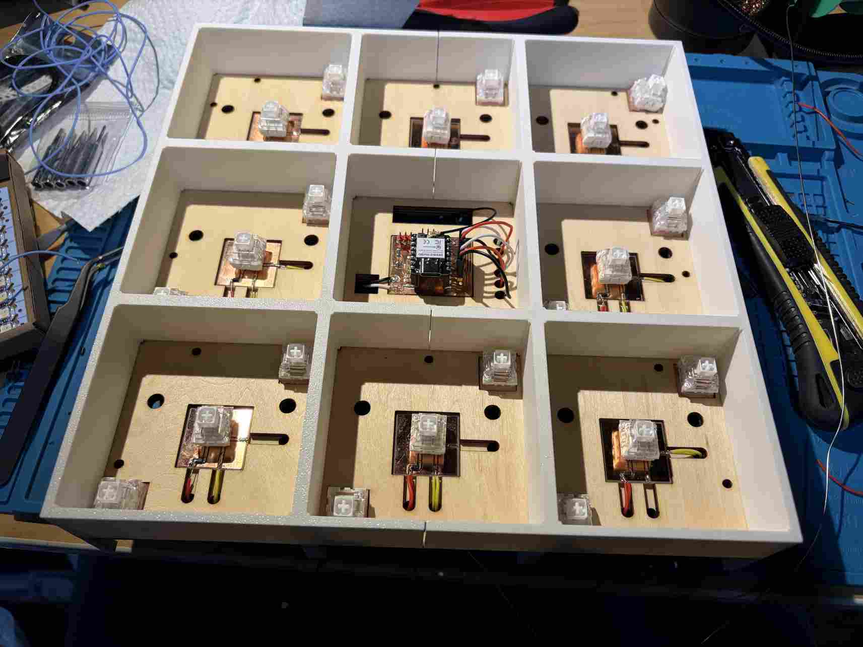
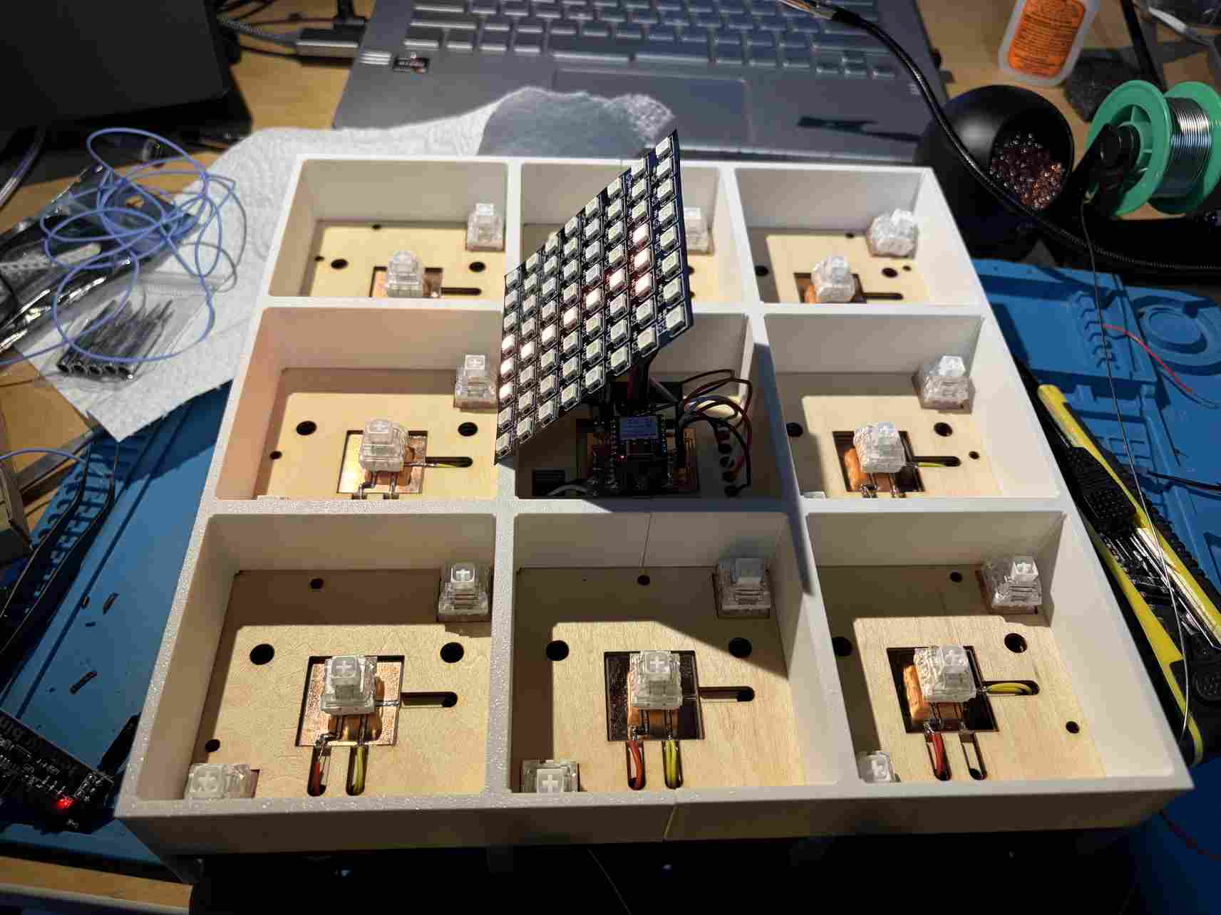
Next was wiring the boards. I ran the wires under the basswood to keep them organized. This required access to the underside. This worked well.
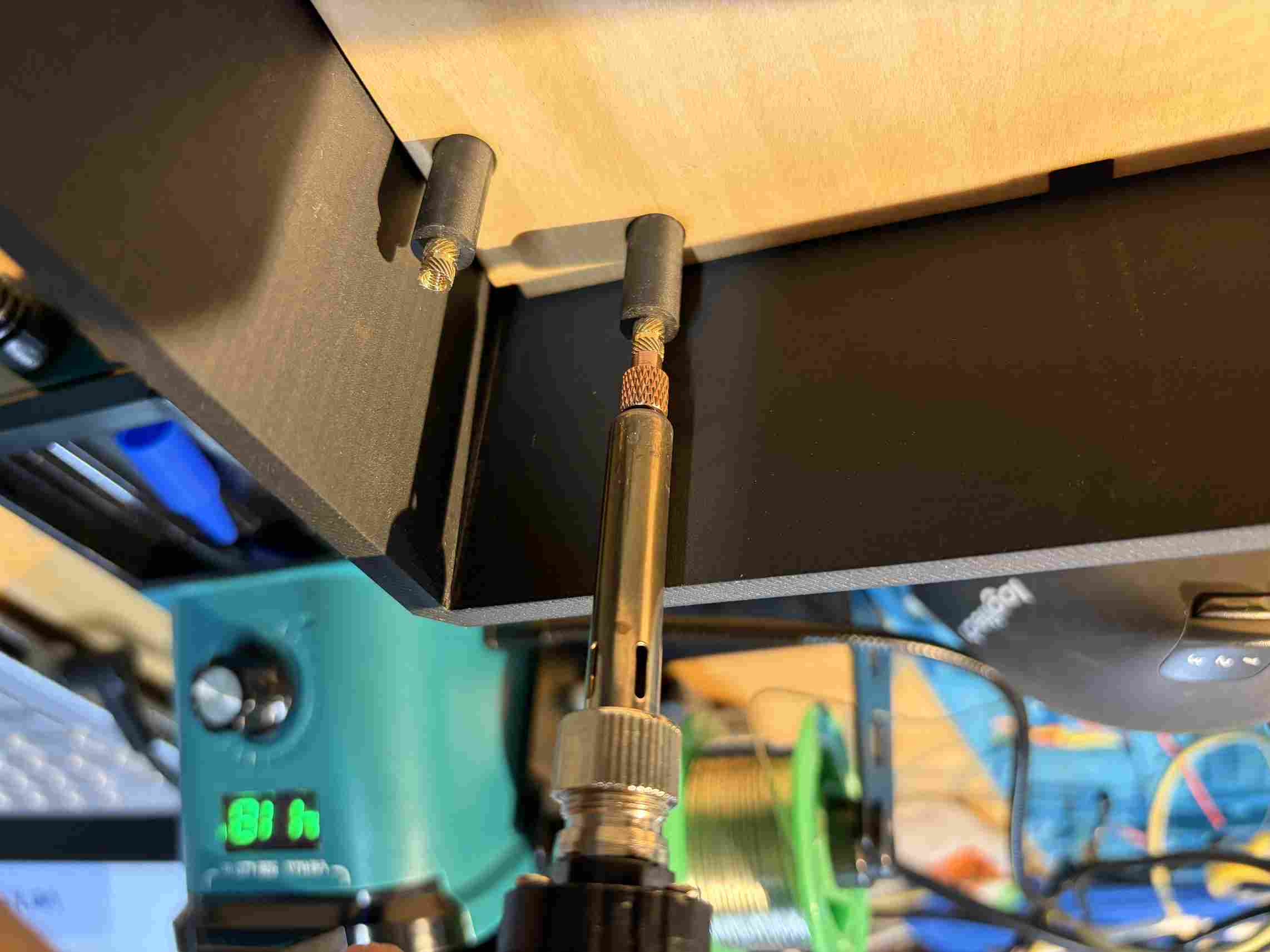
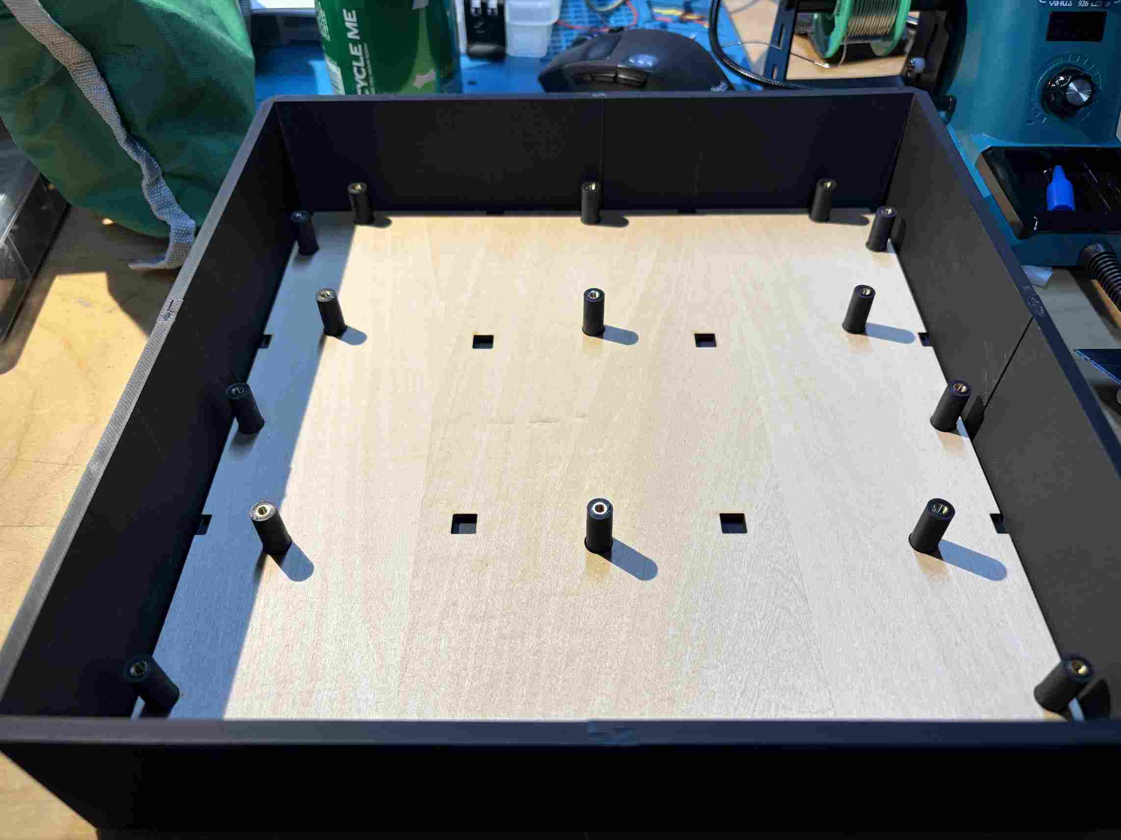
Using a soldering iron, I added heated inserts to the 3D printed screwholes.
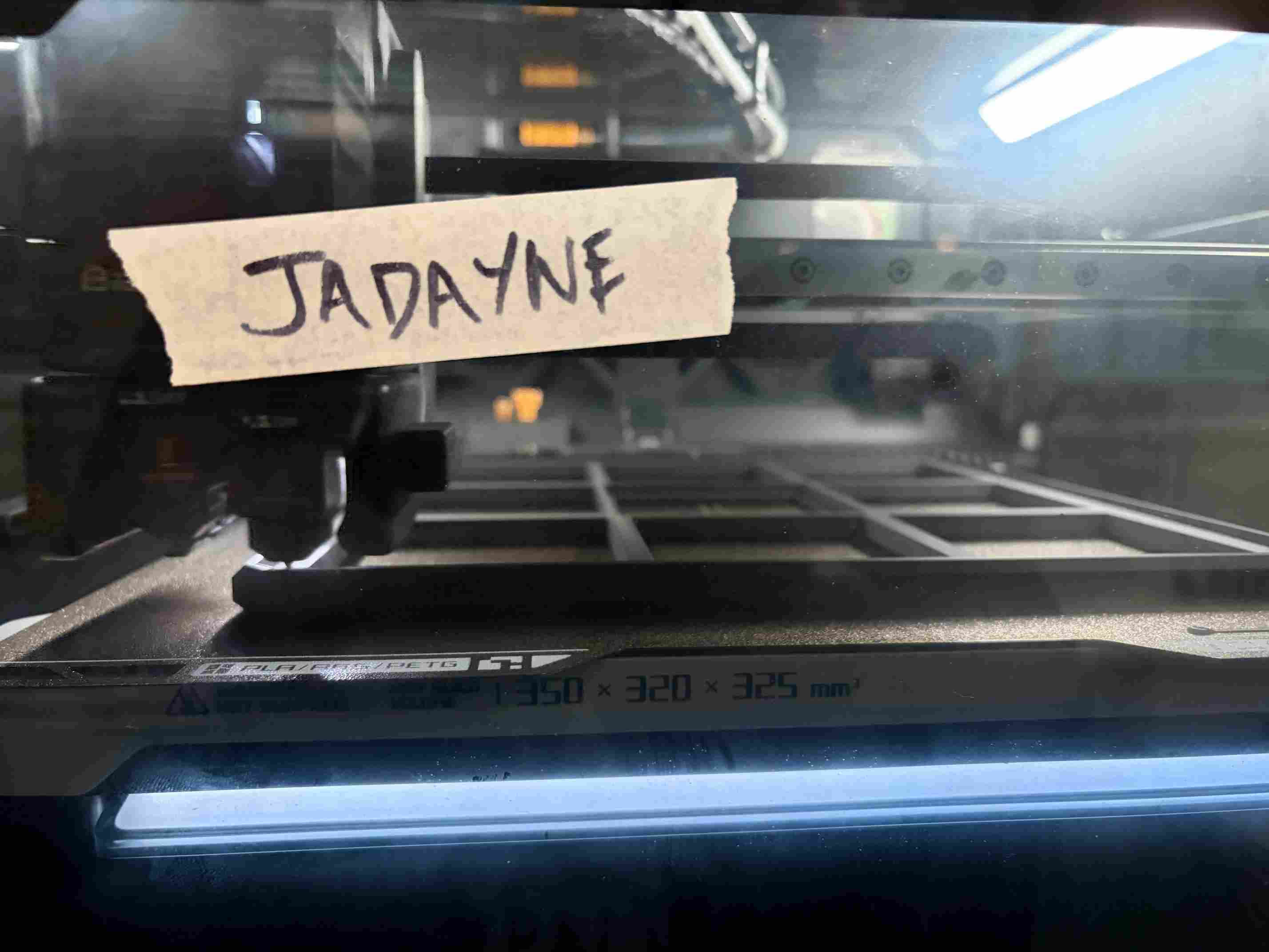
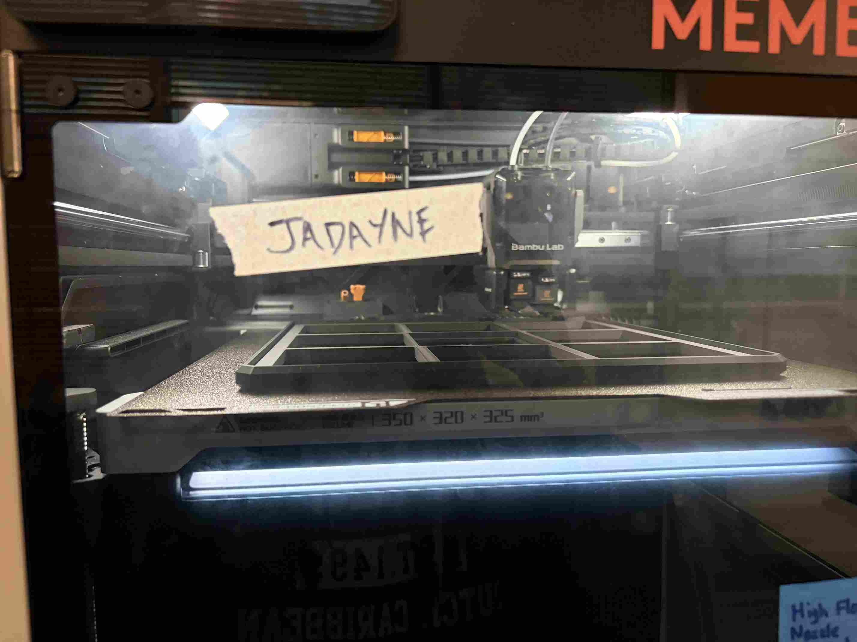
My first round of 3D printing was done using Bambu Lab's P1S printers. Their 10"x10"x10" bed capacity meant that I needed to split the base of my project. When I was printing the top of the enclosure, I was able to use the H2D printer which has a 13.78"x12.60"x12.80" capacity. This allowed me to print the component in 1 piece for a more professional finish.
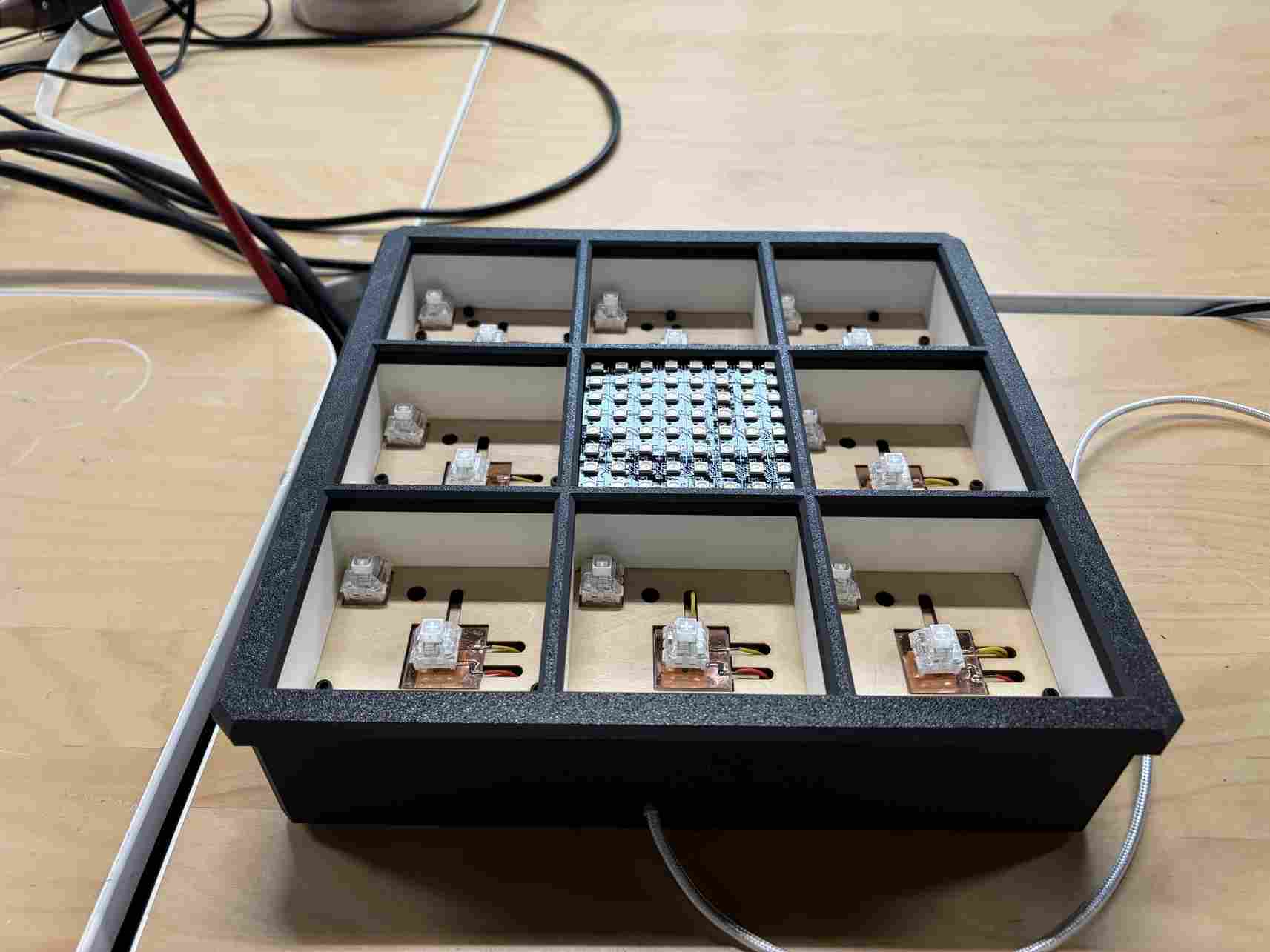
This is the enclosure assembled. You can also see the USB-C cable neatly coming from a small opening in the side. This is connected to a USB-C power supply embedded in the wire compartment.
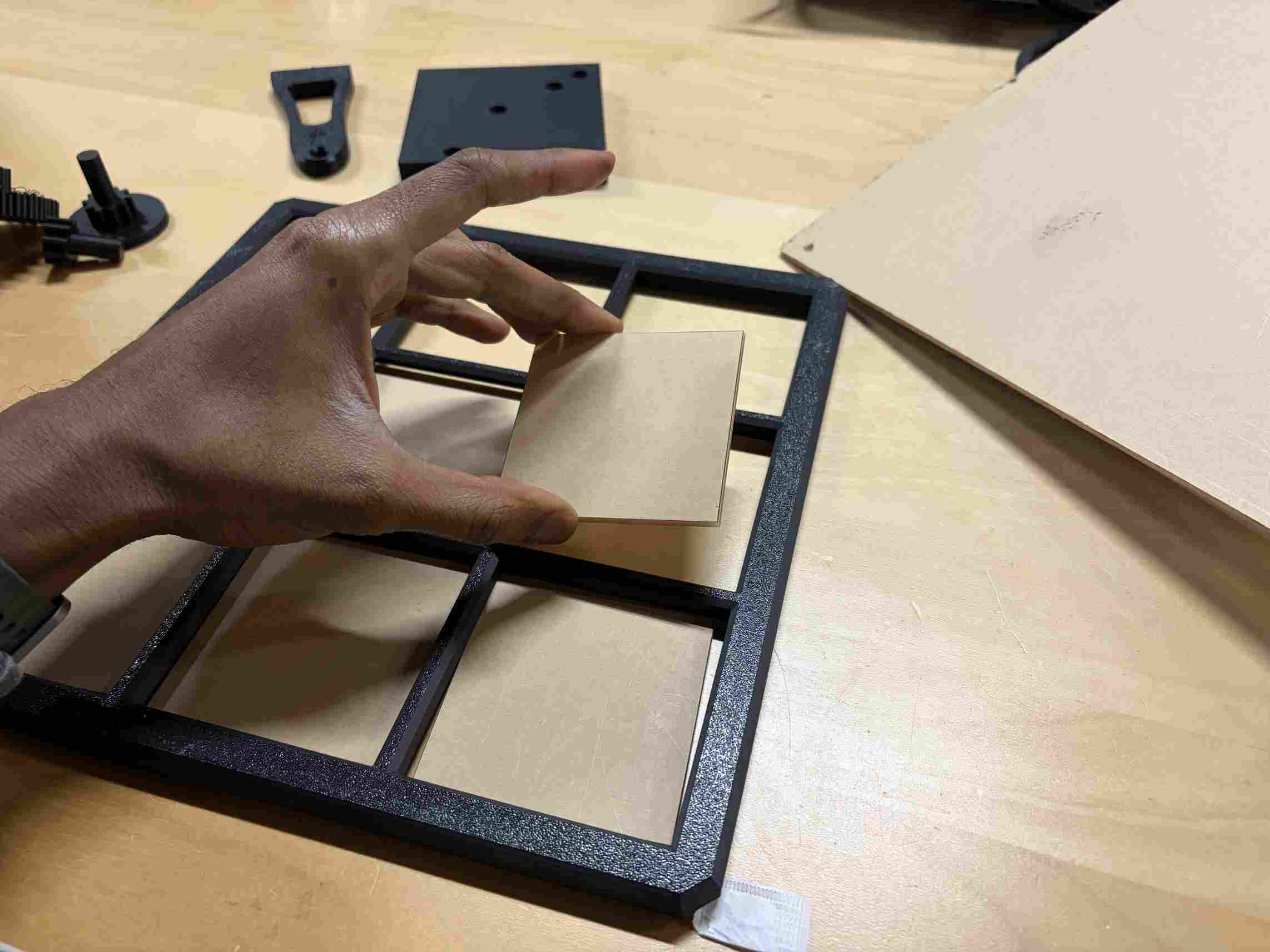
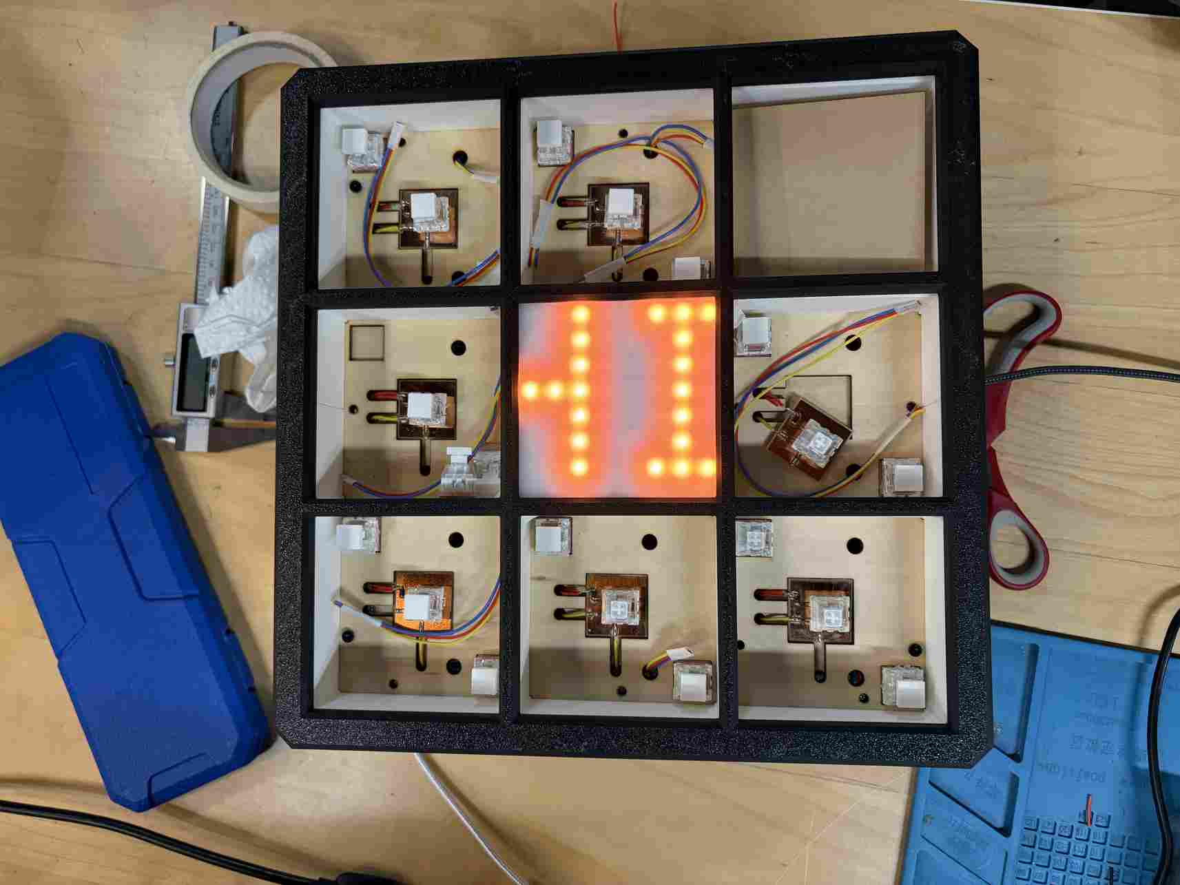
I laser cut the acrylic squares for the tiles and the LED Matrix display.
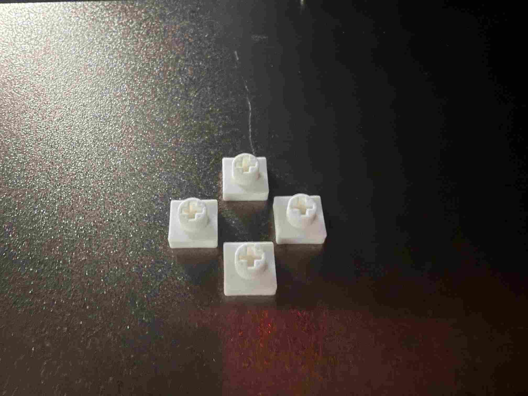
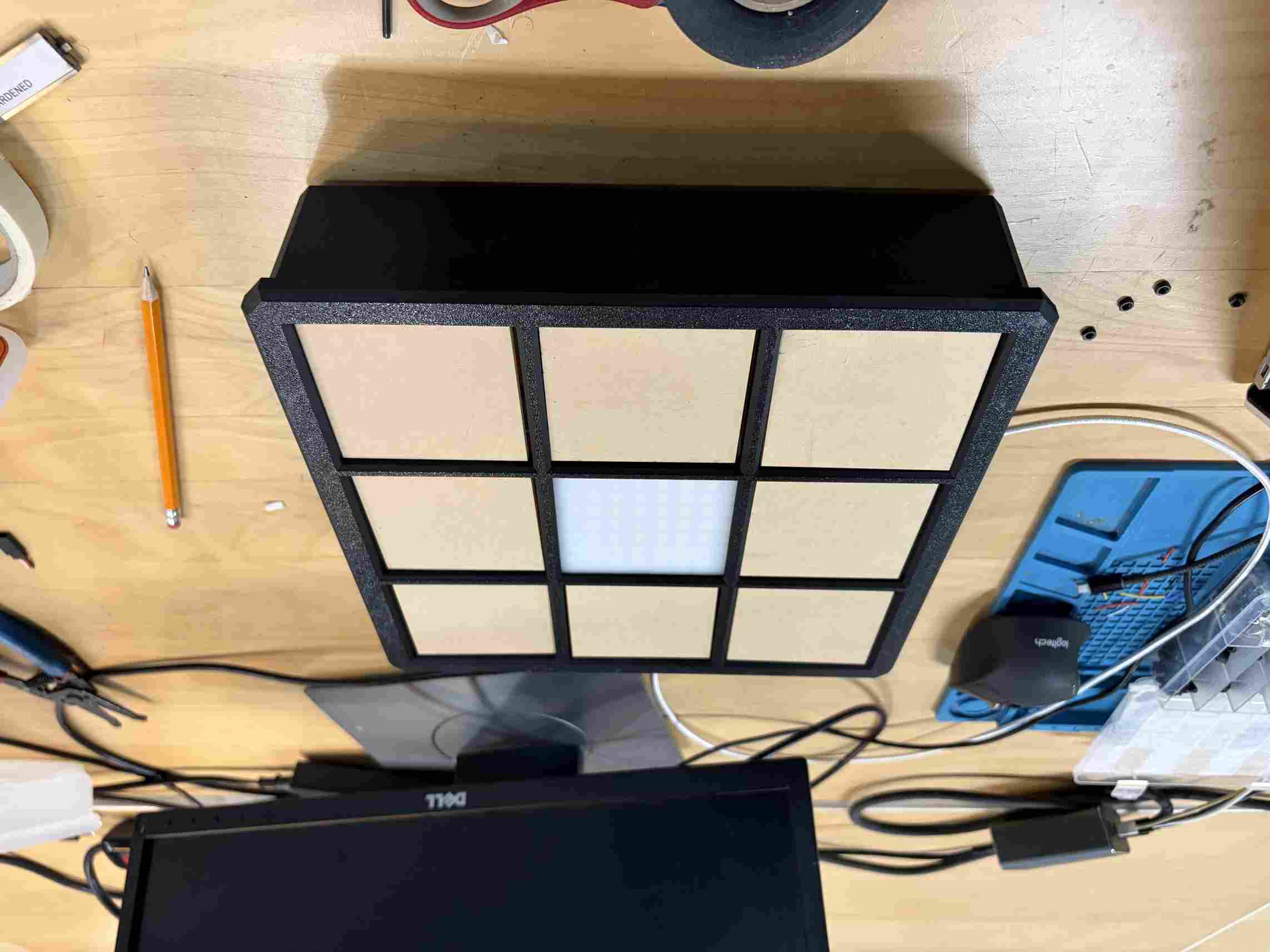
I designed and printed these small caps for the switches to connect them to the LED plates which also support the acrylic tiles.
Click test before gluing.
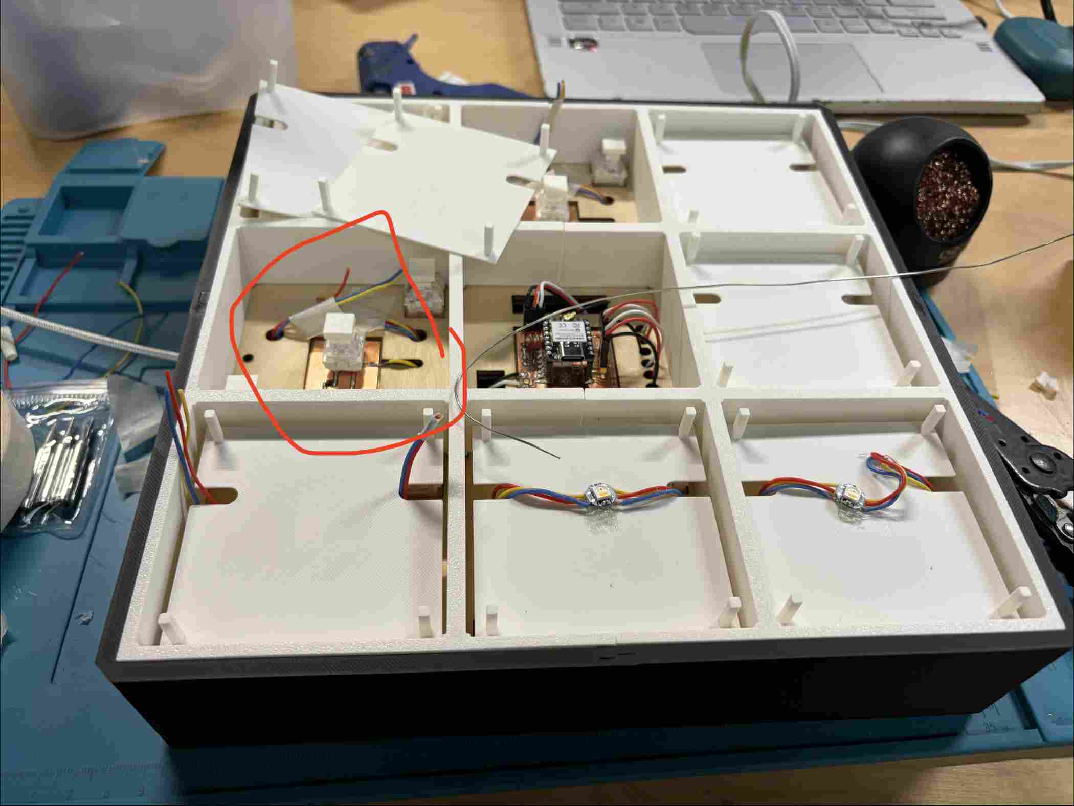
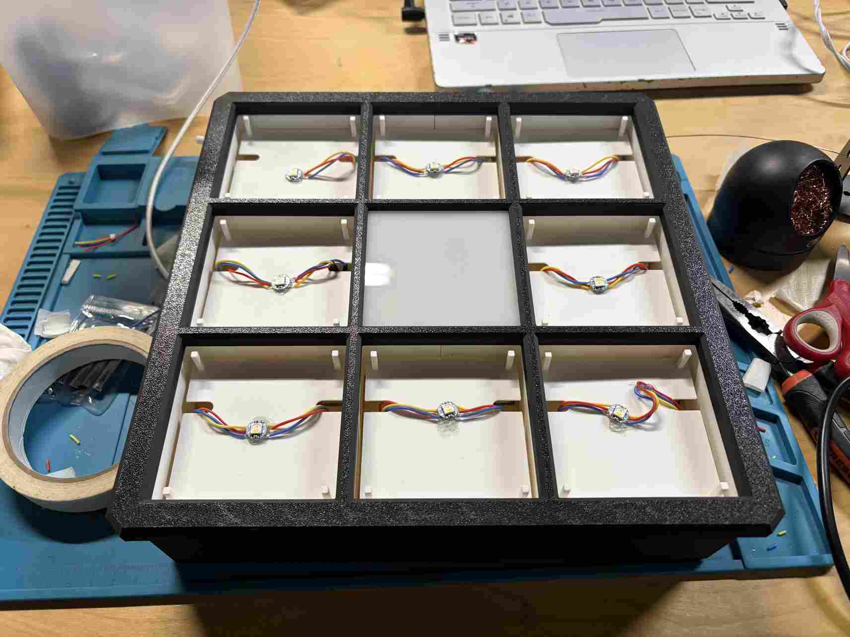
Getting the plates in place, channeling the wires and soldering the LEDs
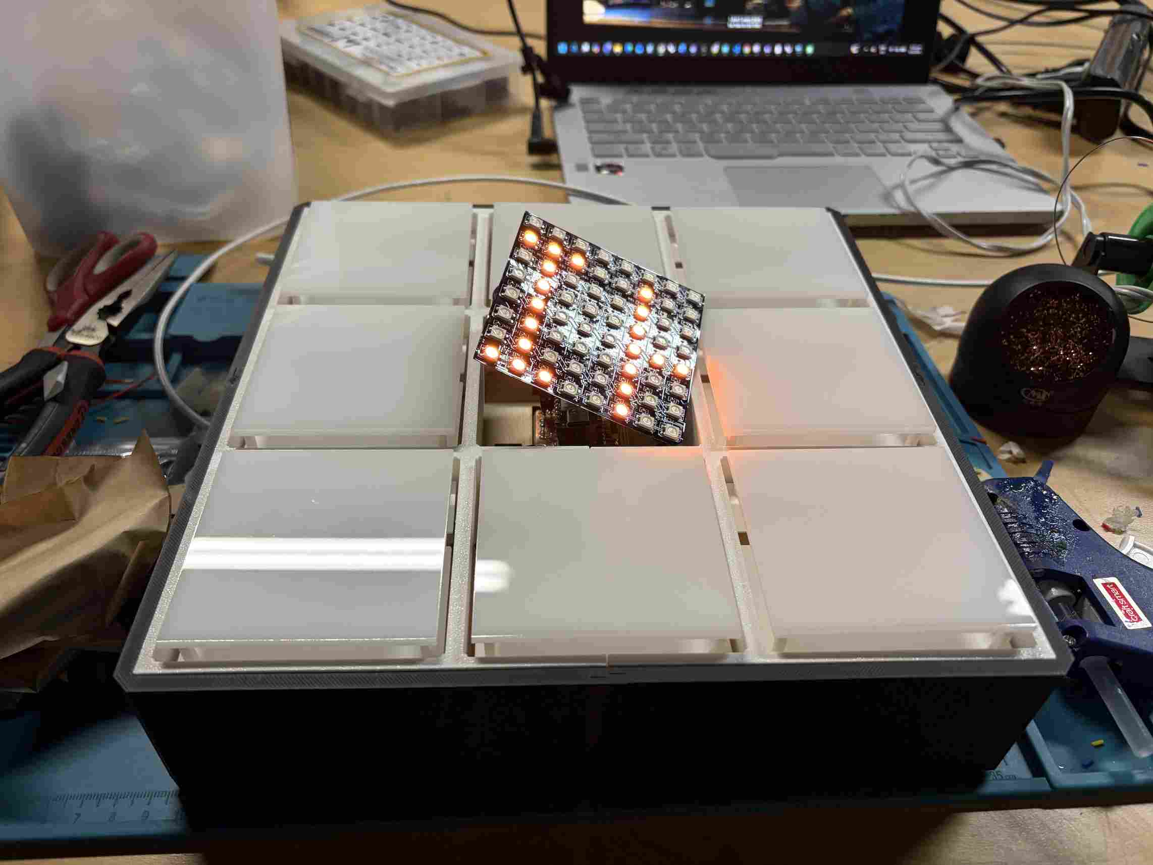
I eventually glued the LED matrix and acrylic to the top frame and put everything together. Next was to troubleshoot the firmware and HTML with Claude's help.
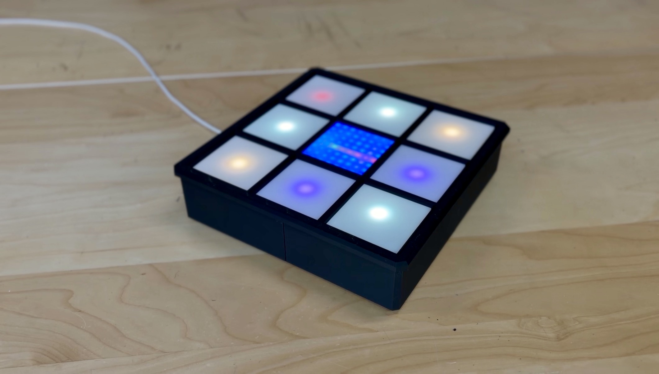
This is the Final Product.
I created the plan for my final project and difining the scope and tracking the progress of my project. I will also be working on the final project and documenting the progress.
What will it do?
My project is wifi enabled interactive game board that allows players to develop their own games of chance, strategy, memory, tivia, or story telling. By using the webapp, players define the outcomes pressing the glowing tiles on the board. this acts as an input. The app can also control the kinds of messages displayed on the LED matrix in the center of the board.
Who has done what beforehand?
While developing this project I learned that many people have made macropads. It is a subcategory of a mechanical keyboard and can be customized to do many things. This completely new to me, but I have done the fabrication processes before.
What sources will you use?
I will use youtube tutorials, online forums, and AI tools to guide me.
What will you design
I will design a game board using Rhno 8 for the hardware, KiCad for the PCB, Adobe Illustrator for the graphics, Arduino IDE for the firmware and VS code for the HTML apps
What materials and components will be used?
| Qty | Description | Price | Link |
|---|---|---|---|
| 1 | RGBW LEDS | $20.99 | LED |
| 1 | Seeed Xiao ESP32C3 | $9.99 | Xiao ESP32C3 |
| 1 | LED Matrix | $12.99 | Matrix |
| 1 | USB-C Cables | $9.99 | USB-C Cables |
| 1 | Keyboard switches | $27.90 | Keyboard switches |
| 1 | USB-C Power Supply | $12.99 | Power Supply |
| 1 | Surface Mounted Diodes | $7.99 | SMD |
| 1 | PLA Matte Filament | $10.99 | Filament |
| 1 | Milky White 1/8" Acrylic Sheets | $17.99 | Acrylic |
| 1 | Antenna | $9.99 | Antenna |
| 1 | 18 Gauge Wire | $23.75 | Wire |
| 1 | Hex Screws | $21.99 | Screw |
| 1 | 12"x12" Basswood 1/8" Sheets | $37.99 | Wood |
| 1 | Threaded inserts | $8.99 | Threaded inserts |
Where will they come from?
Amazon, and the Bambu Lab website.
How much will they cost?
The estimated material cost is $234.53
What parts and systems will be made?
The enclosure, PCB, switch cap, player tiles, and display will all be made.
What processes will be used?
I will used 3D printing, laser cutting, PCB milling, soldering, and programming.
What questions need to be answered?
How much can I feasibly accomplish? What skills do I need to develop for this project? How can I make the LEDS, matrix, and switches function? What is the player experience going to be? How can this be developed further?
How will it be evaluated?
It will be evaluated based on meeting the final project requirements, effectiveness of the project and overall completeness.
Project Plan View full details →
Task list and timeline for the Magic 8 project.
The business of creating a product. Planning the steps that come after you've made the thing can be just as important as getting it to work.
Create a dissemination plan for your final project
The plan for Magic 8 is to test it with the homeschool students and campers at Moonlighter FabLab in Miami Beach. As a non-profit that works with the City of Miami Beach, we work with elementary school children in our educational programs. Funding for this kind of product can be related to some of our grants. As our demand grows, we can use funding from paid workshops and product sales to offset the cost of production. This is not intended to be a large scale production because we want to encourage curiosity within our STEAM community. We will also include Magic 8 in our annual Maker Faire Miami and Education Day. This would be a great opportunity to share it with a wider population of public school students in Miami-Dade and Broward County, Florida.
Outline future possibilities and described how to make them probabilities
As the project develops further, I can be included as a STEAM kit for more of the classes taught at Moonlighter. The next stage would be to market it to other STEAM programs in South Florida and to parents interested in interactive games for their families.
What tasks have been completed and what tasks remain?
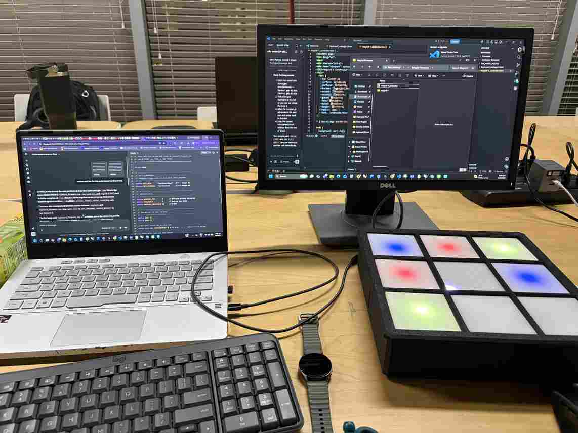
The physical project has been completed. I am still working on the coding for the firmware and webapp to ensure everything works properly.
What's working? What's not?
The individual LEDs are turning on, the webapp is able to connect to the microcontroller via the websocket and hostname, the LED matrix is receiving messages from the webapp. The current issue is getting the switch inputs to work and for the individual LEDs to respond as commanded.
What questions need to be resolved?
If I try a different programming language, will the issues be resolved? Do I need a second microcontroller? to accommodate all of my intended functions? How can I make the device smaller and more robust?
Planned what will happen when?
Magic 8 will be introduced to Moonlight FabLab's camper this Summer during our Summer Maker Camp. Maker Faire Miami 2027 will be the best time to launch it more publicly in the Spring. It can them be introduced to more school Fall 2027 and be open for public purchase in time for the 2027 Holiday season.
What have you learned?
I have learned a lot about the processes of producing a product. Going beyond the basics of digital fabrication, I learned the ways these tools can be used to consistently and reliably produce high quality work. I also learned the value of coding and understanding hardware and how hardware and software interact.
Licensing
This project is released under a strongly-reciprocal, open-source license bundle:
Hardware (game board + PCB): CERN-OHL-S v2
Firmware & webapp: GPL v3
Documentation & media (Fab page, in-app messages, graphics): CC BY-SA 4.0
Claude SessionWhy this choice
I chose strong copyleft across every layer of the project so that the customizable-games ecosystem stays open. Anyone who builds on the board, the firmware, or the documentation is required to release their version under the same terms. No one can take this teaching tool, improve it, and lock it behind a closed or proprietary product. Selling units is fully permitted, which matters since this will be distributed through Moonlighter FabLab and potentially other organizations. This bundle also matches Fab Academy's own default license (CC BY-SA), keeping the project consistent with the open-education community it comes from. The trade-off is that a company can't absorb the design into a closed commercial product without also open-sourcing their changes. For an educational tool built to be shared and remixed by kids and educators, that's the intended outcome rather than a limitation.
Footer license notice
© Jadayne A. Smith, 2026. Hardware licensed under CERN-OHL-S v2. Firmware and webapp licensed under GNU GPL v3.0. Documentation and media licensed under CC BY-SA 4.0. Full license texts and source files available at [your repo link].
This project is not affiliated with or endorsed by CERN, the Free Software Foundation, or Creative Commons.