

9. Input Devices
This week I explored input devices and how they can be used to interact with microcontrollers. I built a simple servo motor control system using buttons to move the servo to different positions.
Week 9 Group AssignmentThe Code
    #include

Servo myServo;

const int SERVO_PIN   = D5;   // GPIO7  — signal wire
const int BUTTON_180  = D0;   // GPIO2  — press to go to 180 degrees
const int BUTTON_0    = D1;   // GPIO3  — press to go to 0 degrees

int currentAngle = 0;

void setup() {
  Serial.begin(115200);

  // Internal pull-up: pin reads HIGH normally, LOW when button pressed
  pinMode(BUTTON_180, INPUT_PULLUP);
  pinMode(BUTTON_0,   INPUT_PULLUP);

  myServo.attach(SERVO_PIN, 500, 2500);
  myServo.write(currentAngle);
  delay(1000);

  Serial.println("Ready. Press a button.");
}

void loop() {
  // Button pressed = pin goes LOW (because other leg is GND)
  if (digitalRead(BUTTON_180) == LOW) {
    if (currentAngle != 180) {
      currentAngle = 180;
      myServo.write(currentAngle);
      Serial.println("Moving to 180 degrees.");
    }
    delay(200);  // Debounce
  }

  if (digitalRead(BUTTON_0) == LOW) {
    if (currentAngle != 0) {
      currentAngle = 0;
      myServo.write(currentAngle);
      Serial.println("Moving to 0 degrees.");
    }
    delay(200);  // Debounce
  }
}
The code is a simple Arduino sketch that controls a servo motor using two buttons. When the first button is pressed, the servo moves to 180 degrees, and when the second button is pressed, it moves to 0 degrees.
Testing the Code With a Breadboard
I got the servo to work on the first try which was amazing! It was a sign that I have actually been learning over the time I have been in Fab Academy.
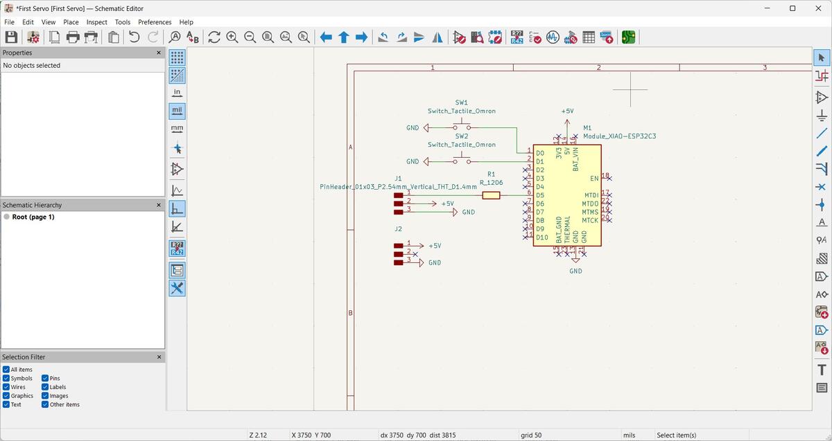
Next I used KiCad to layout the Schematic for the PCB.
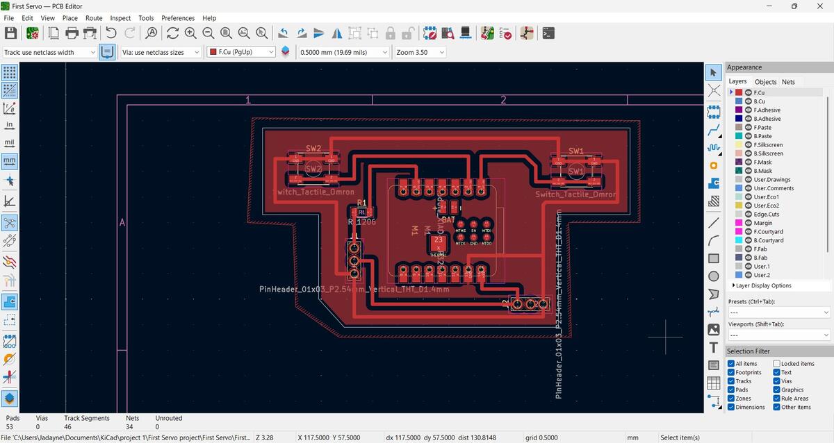
I designed the PCB to be almost like a handheld controller.
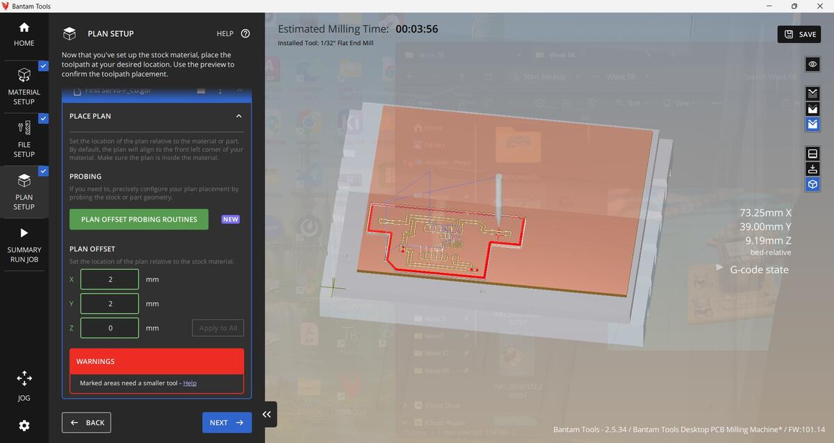
Setting up the Bantam tool was also very easy this time around.
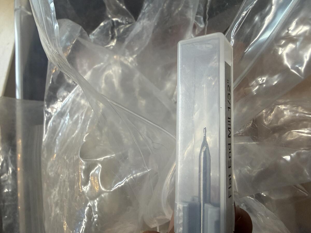

I loaded the 1/32" Flat end mill into the Bantam tool.
It was a very quick cut with the 1/32" flat end mill.
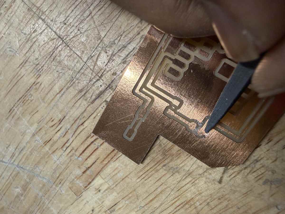
I learned from this PCB that it is important to listen to the guidance from the pograms. The Bantam advised me to start with a smaller end mill to start the cut and end with the 1/32". This would have eliminated the need for what I am doing here. I had to use a rasp to file away the copper between my 5V and grong connections.
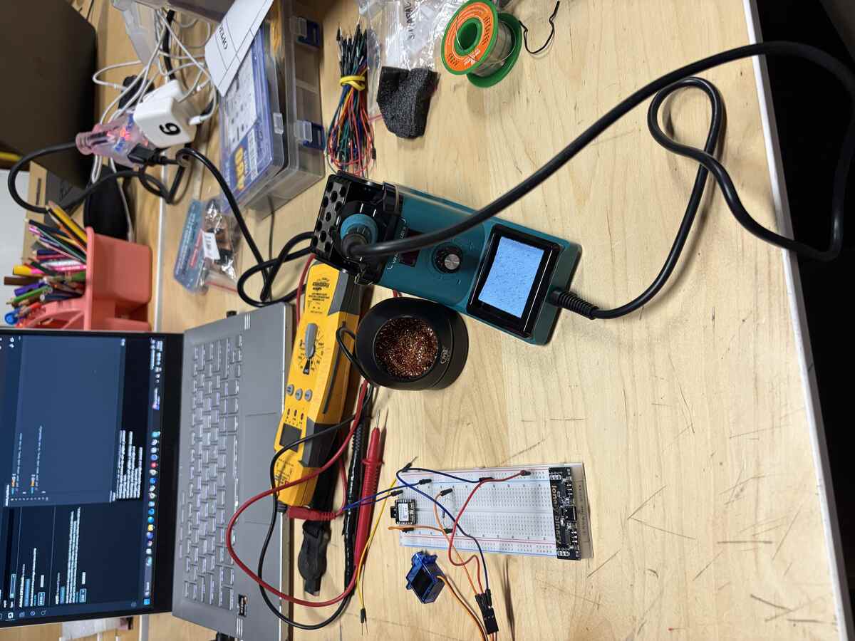
Unboxing a new soldering iron setup.
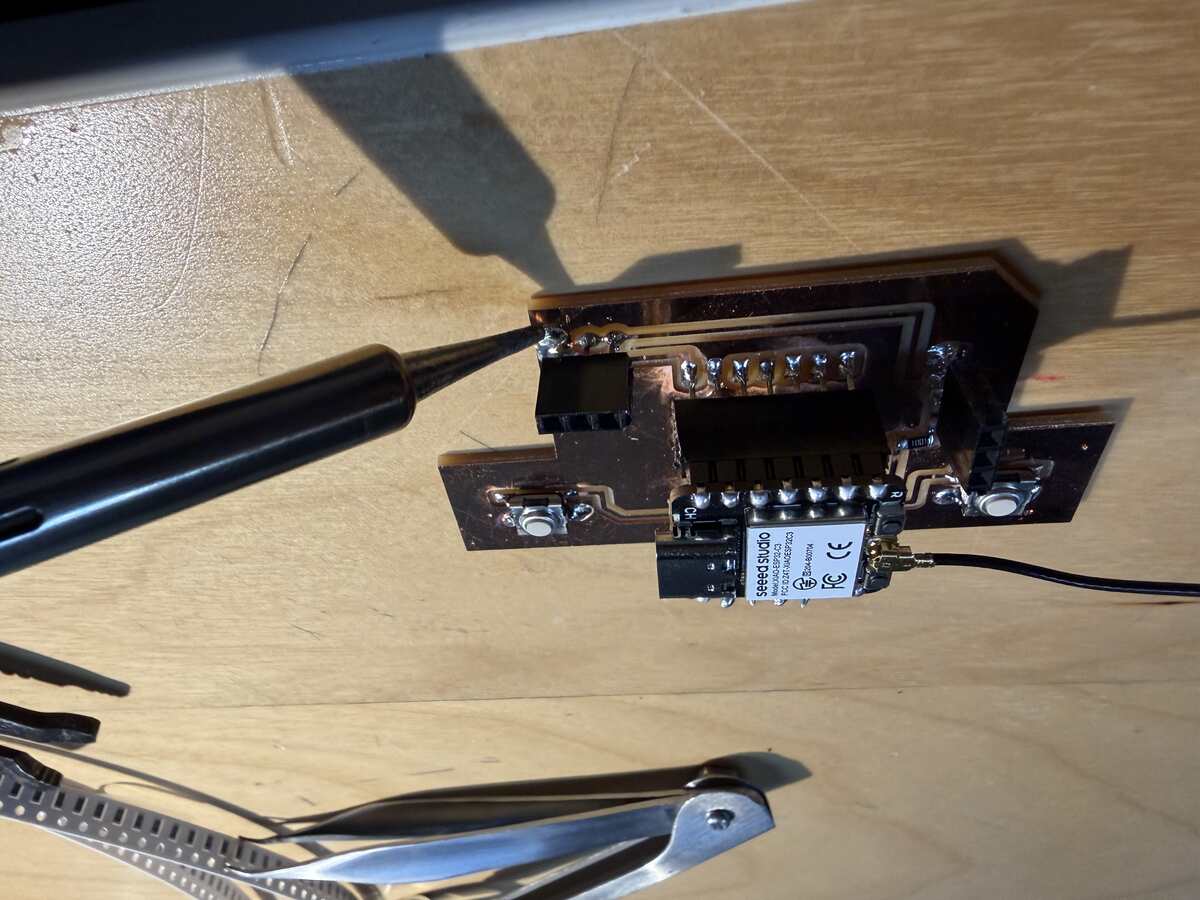
Soldering the components onto the PCB.
All of the components assembled and ready for testing.
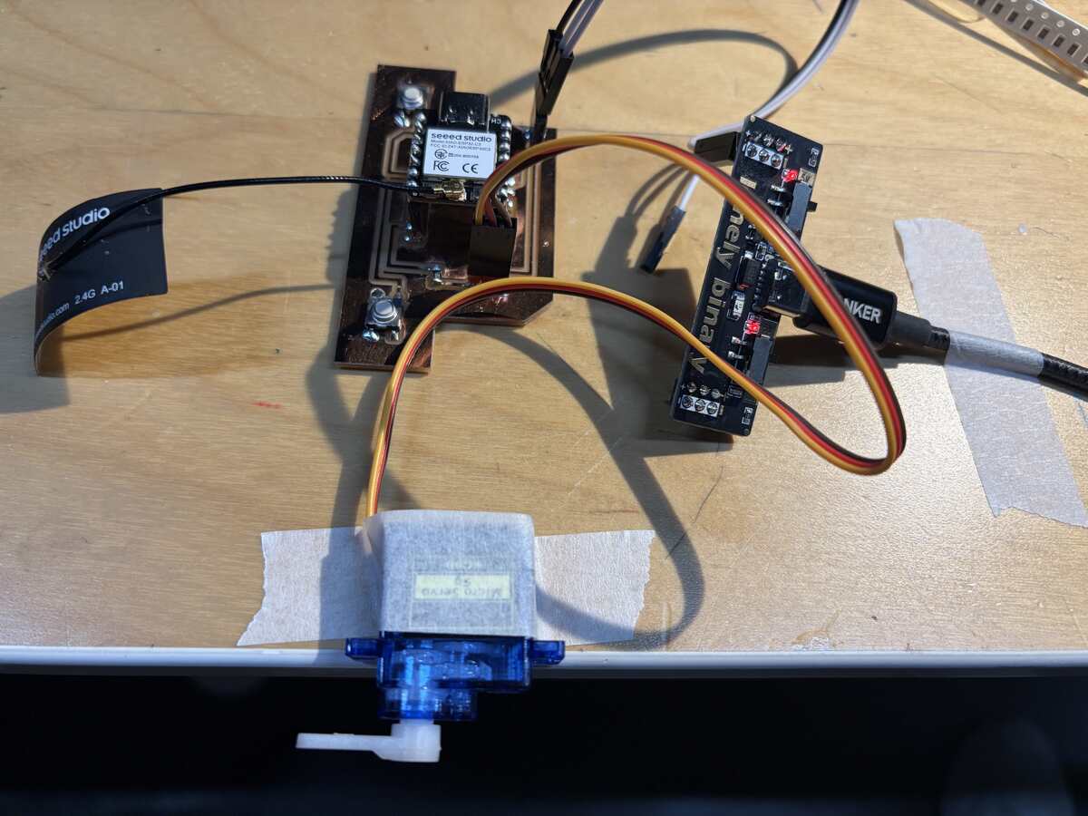
Testing the PCB and Microcontroller
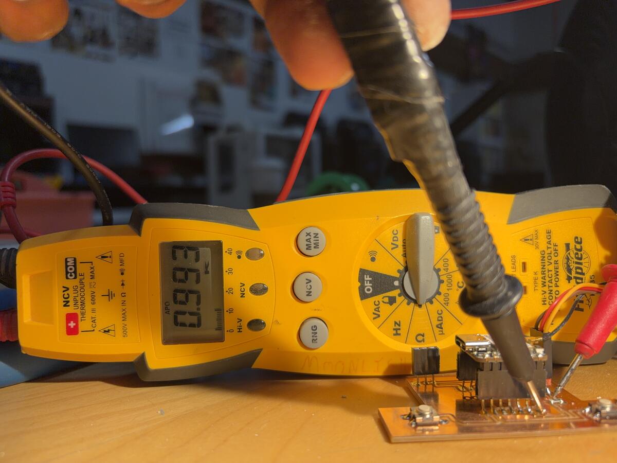
I used the multimeter to test the resistance on the date cannection to the servo. It confirmed that there were 1k ohms of resistance as specified by my AI instruction sheet.
I also saw good continuity from my microcontroller to the servo trace.
The switches worked consistently throughout the testing process.
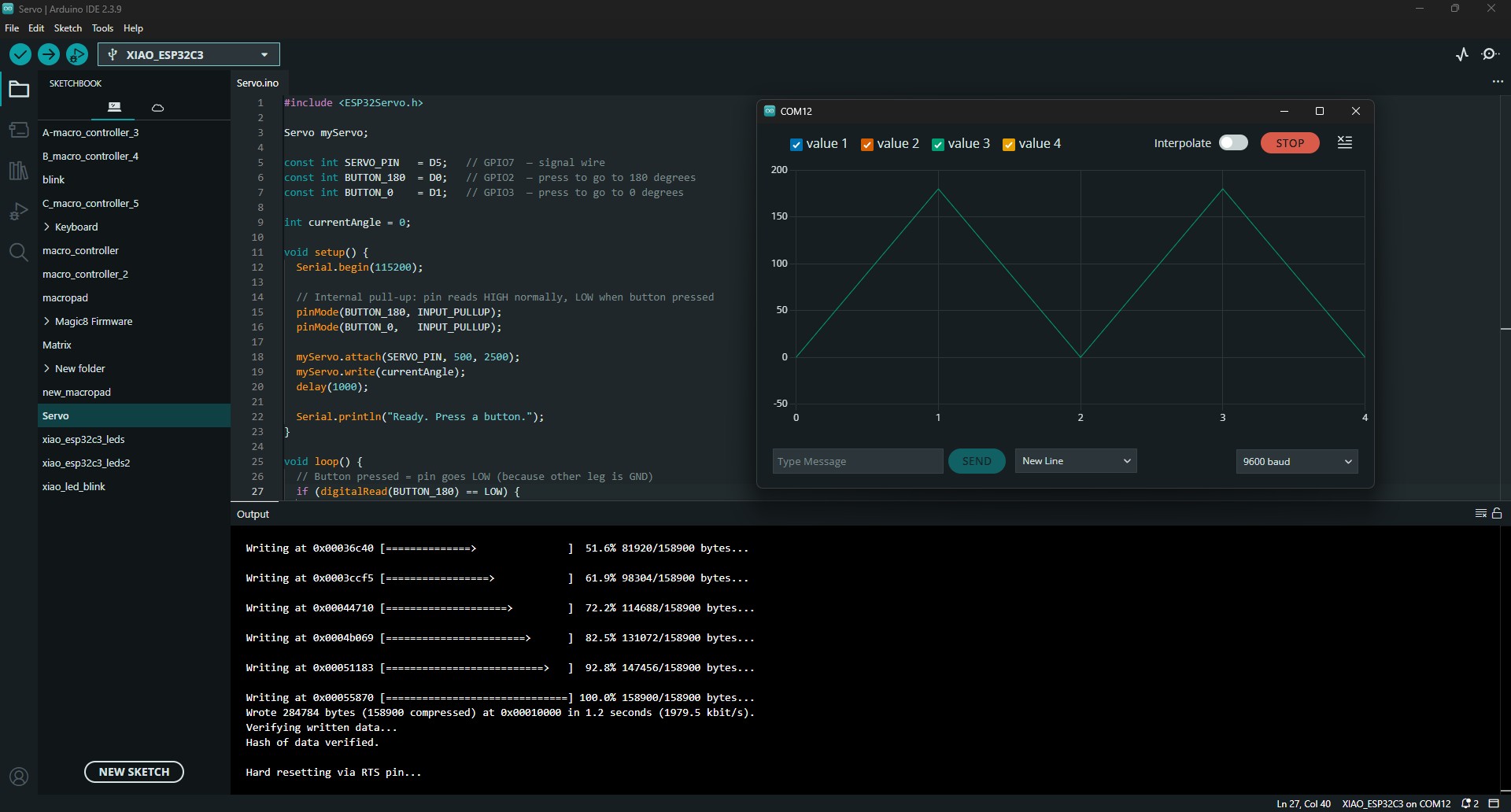
The Serial Plotter in Arduino IDE mapped the signal from each push of the switches. Graph is showing that the first switch on D0 is sending the signal for a 180 degree rotation. The second switch on D1 is sending the signal to return to 0. The signals are sent at a uniform rate once the switches are pressed.
Group Project
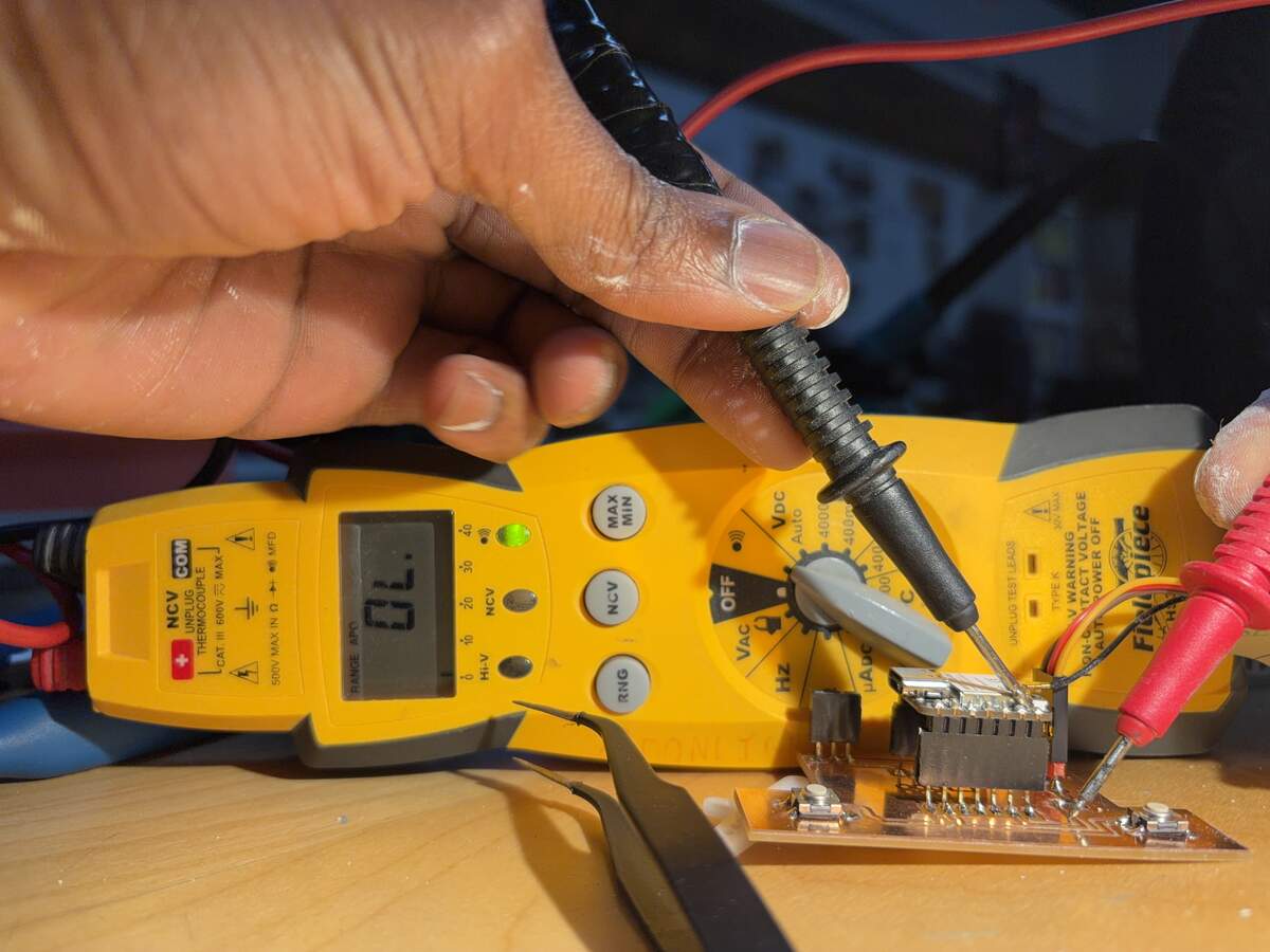
Testing the Multimeter and Oscilloscope on an Input Device.
When the switch is not pressed, there is no reading, but when the switch is pressed a low resistance ranging from 0.3-0.5ohm is observed.
This reading shows that there is a voltage reading of 3.289V when the switch is not pressed which goes to 0.0V when it is pressed.
Adjusting the horizontal reading on the oscilloscope allowed me to see the waves more clearly.
What's interesting with this reading is that there is a secondary wave that fluctuates at the same rate as the LED lights. This was with the blue light. Let's see if the waves look different with the red light.
The is a noticeable difference in the distortion of the wave when I switch between Blue and Red light. The Blue light has seems to have less fluctuations and appears to be behind the primary wave. The Red light seems to have more distortion and appear to be infront of the main wave. When there is no light, the secondary waves disappear.