

10. Output Devices
This week's assignment is to add an output device to a micro controller I designed and program it to do something.
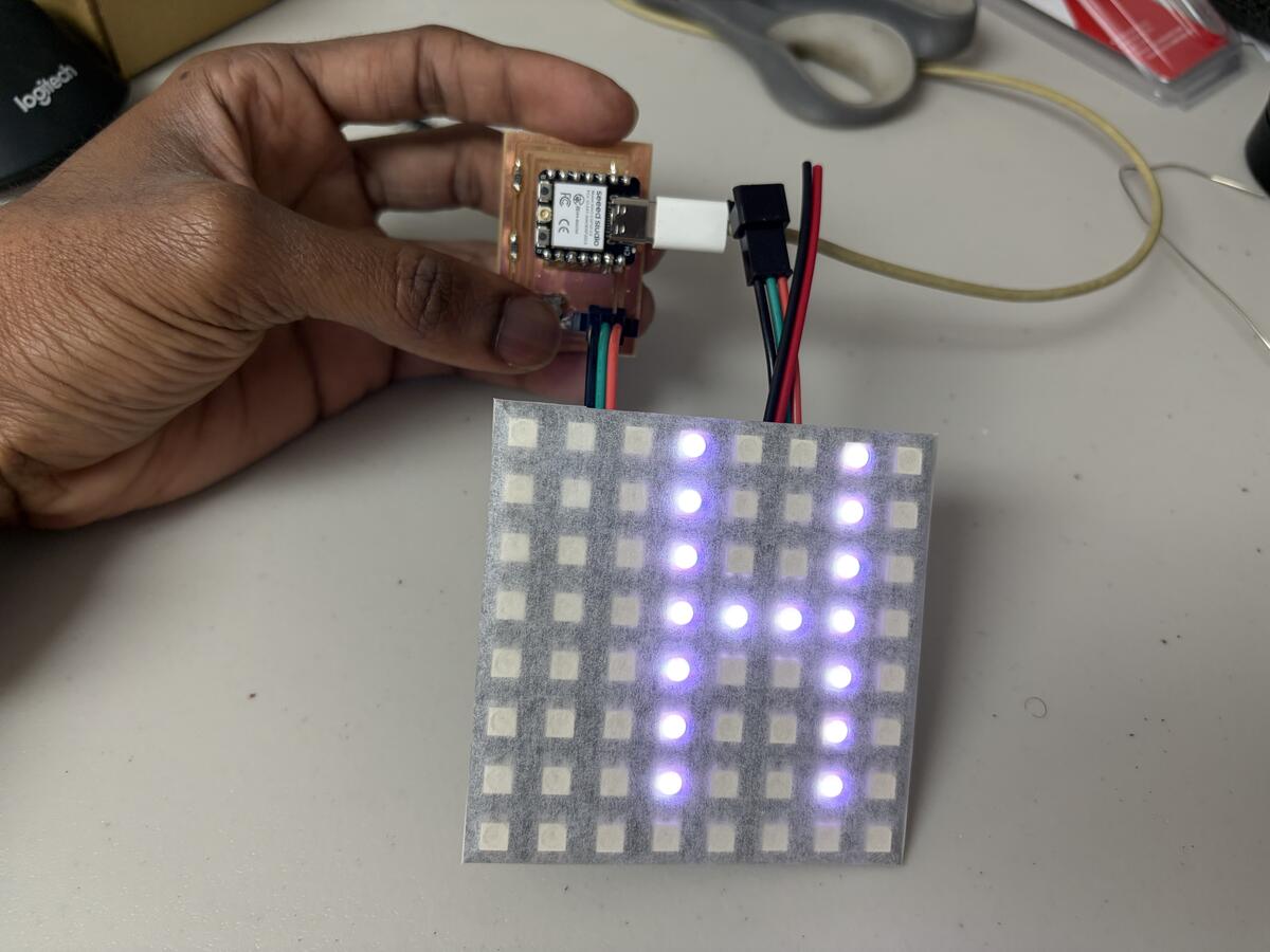
Week 10 Group AssignmentSo far, I have designed and assembled PCBs that blink LEDs and control a servo. For my outputs week I wanted to go a step further with the LEDs. Using an 8x8 LED matrix, a Seeed Xiao ESP32-c3 and a surface mounted switch, I created a display with scrolling text which reads "HELLO WORLD" when I press the switch and turns off when I press the switch again.
I asked Claude to walk me through the process based on the components I had available. I gave me a full explanation of how to connect the components and write the code to make the LED matrix display the scrolling text. See the code below.
    /*
NEW SKETCH

  8x8 WS2812B LED Matrix - Scrolling Text "0 WORLD" with Start/Stop Switch
  Hardware: Seeed XIAO ESP32C3
  Data Pin: GPIO2
  Switch Pin: GPIO3 (connect switch between GPIO3 and GND)
*/

#include

#define DATA_PIN     2
#define SWITCH_PIN   3      // GPIO3 — connect switch between GPIO3 and GND
#define NUM_LEDS     64
#define BRIGHTNESS   20
#define SCROLL_DELAY 80     // ms between scroll steps

Adafruit_NeoPixel strip(NUM_LEDS, DATA_PIN, NEO_GRB + NEO_KHZ800);

// Text color
#define TEXT_R 255
#define TEXT_G 255
#define TEXT_B 255

// 5x7 Font
const uint8_t font5x7[][5] = {
  { 0b1111111, 0b0001000, 0b0001000, 0b1111111, 0b0000000 }, // H
  { 0b1111111, 0b1001001, 0b1001001, 0b1000001, 0b0000000 }, // E
  { 0b1111111, 0b1000000, 0b1000000, 0b1000000, 0b0000000 }, // L
  { 0b1111111, 0b1000000, 0b1000000, 0b1000000, 0b0000000 }, // L
  { 0b0111110, 0b1000001, 0b1000001, 0b0111110, 0b0000000 }, // O
  { 0b0000000, 0b0000000, 0b0000000, 0b0000000, 0b0000000 }, // (space)
  { 0b1111111, 0b0100000, 0b0010000, 0b0100000, 0b1111111 }, // W
  { 0b0111110, 0b1000001, 0b1000001, 0b0111110, 0b0000000 }, // O
  { 0b1111111, 0b0001001, 0b0011001, 0b1100110, 0b0000000 }, // R
  { 0b1111111, 0b1000000, 0b1000000, 0b1000000, 0b0000000 }, // L
  { 0b1111111, 0b1000001, 0b1000001, 0b0111110, 0b0000000 }, // D
};

const int NUM_CHARS  = 11;
const int TOTAL_COLS = NUM_CHARS * 6;

uint8_t scrollBuf[7][NUM_CHARS * 6];

// --- State ---
bool animRunning  = false;   // is animation playing?
int  scrollOffset = -8;      // current scroll position

// --- Debounce ---
bool     lastSwitchState    = HIGH;
bool     switchState        = HIGH;
unsigned long lastDebounceTime = 0;
#define DEBOUNCE_DELAY 50

void buildScrollBuffer() {
  for (int c = 0; c < NUM_CHARS; c++) {
    for (int col = 0; col < 5; col++) {
      uint8_t colData = font5x7[c][col];
      for (int row = 0; row < 7; row++) {
        scrollBuf[row][c * 6 + col] = (colData >> row) & 1;
      }
    }
    for (int row = 0; row < 7; row++) {
      scrollBuf[row][c * 6 + 5] = 0;
    }
  }
}

void displayFrame(int offset) {
  strip.clear();
  for (int col = 0; col < 8; col++) {
    int srcCol = offset + col;
    for (int row = 0; row < 7; row++) {
      uint8_t lit = 0;
      if (srcCol >= 0 && srcCol < TOTAL_COLS) {
        lit = scrollBuf[row][srcCol];
      }
      if (lit) {
        int ledIndex;
        if (col % 2 == 0) {
          ledIndex = col * 8 + row;
        } else {
          ledIndex = col * 8 + (7 - row);
        }
        strip.setPixelColor(ledIndex, strip.Color(TEXT_R, TEXT_G, TEXT_B));
      }
    }
  }
  strip.show();
}

// Read switch with debounce — returns true on a LOW transition (button press)
bool switchPressed() {
  bool reading = digitalRead(SWITCH_PIN);

  if (reading != lastSwitchState) {
    lastDebounceTime = millis();
  }
  lastSwitchState = reading;

  if ((millis() - lastDebounceTime) > DEBOUNCE_DELAY) {
    if (reading != switchState) {
      switchState = reading;
      if (switchState == LOW) {  // Active LOW — pressed
        return true;
      }
    }
  }
  return false;
}

void setup() {
  Serial.begin(115200);

  pinMode(SWITCH_PIN, INPUT_PULLUP);  // Internal pull-up; switch connects GPIO3 → GND

  strip.begin();
  strip.setBrightness(BRIGHTNESS);
  strip.clear();
  strip.show();

  buildScrollBuffer();
  Serial.println("Ready. Press switch to start/stop.");
}

void loop() {
  // Always check the switch, even mid-scroll
  if (switchPressed()) {
    animRunning = !animRunning;
    Serial.println(animRunning ? "▶ Started" : "⏹ Stopped");

    if (!animRunning) {
      // Clear display immediately on stop
      strip.clear();
      strip.show();
      scrollOffset = -8;  // Reset position for next start
    }
  }

  if (animRunning) {
    displayFrame(scrollOffset);
    scrollOffset++;

    // Reset after full scroll
    if (scrollOffset >= TOTAL_COLS) {
      scrollOffset = -8;
    }

    // Non-blocking delay — still checks switch during scroll pause
    unsigned long start = millis();
    while (millis() - start < SCROLL_DELAY) {
      if (switchPressed()) {
        animRunning = false;
        strip.clear();
        strip.show();
        scrollOffset = -8;
        Serial.println("⏹ Stopped");
        break;
      }
    }
  }
}
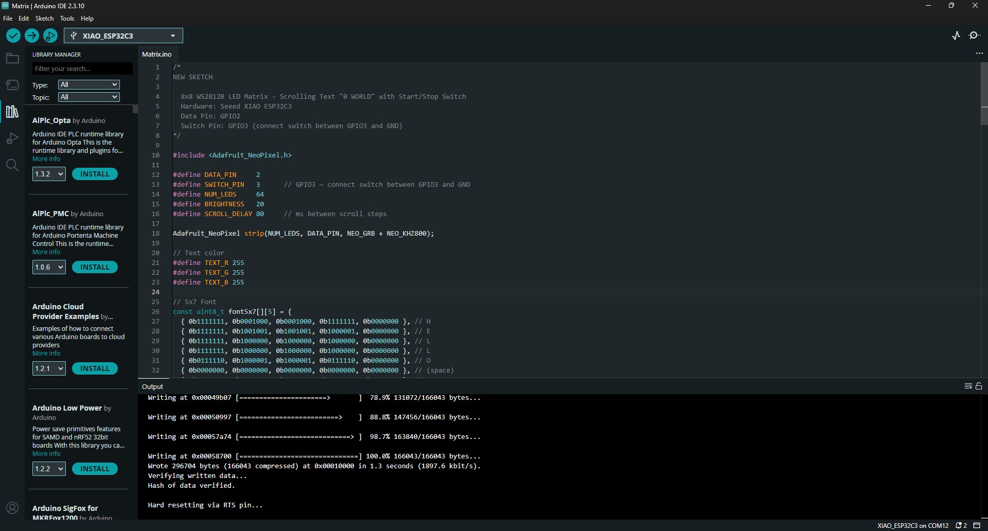
I opened the Matrix.ino file containing the code in the Arduino IDE. This allowed me to connect my microcontroller and run the program.
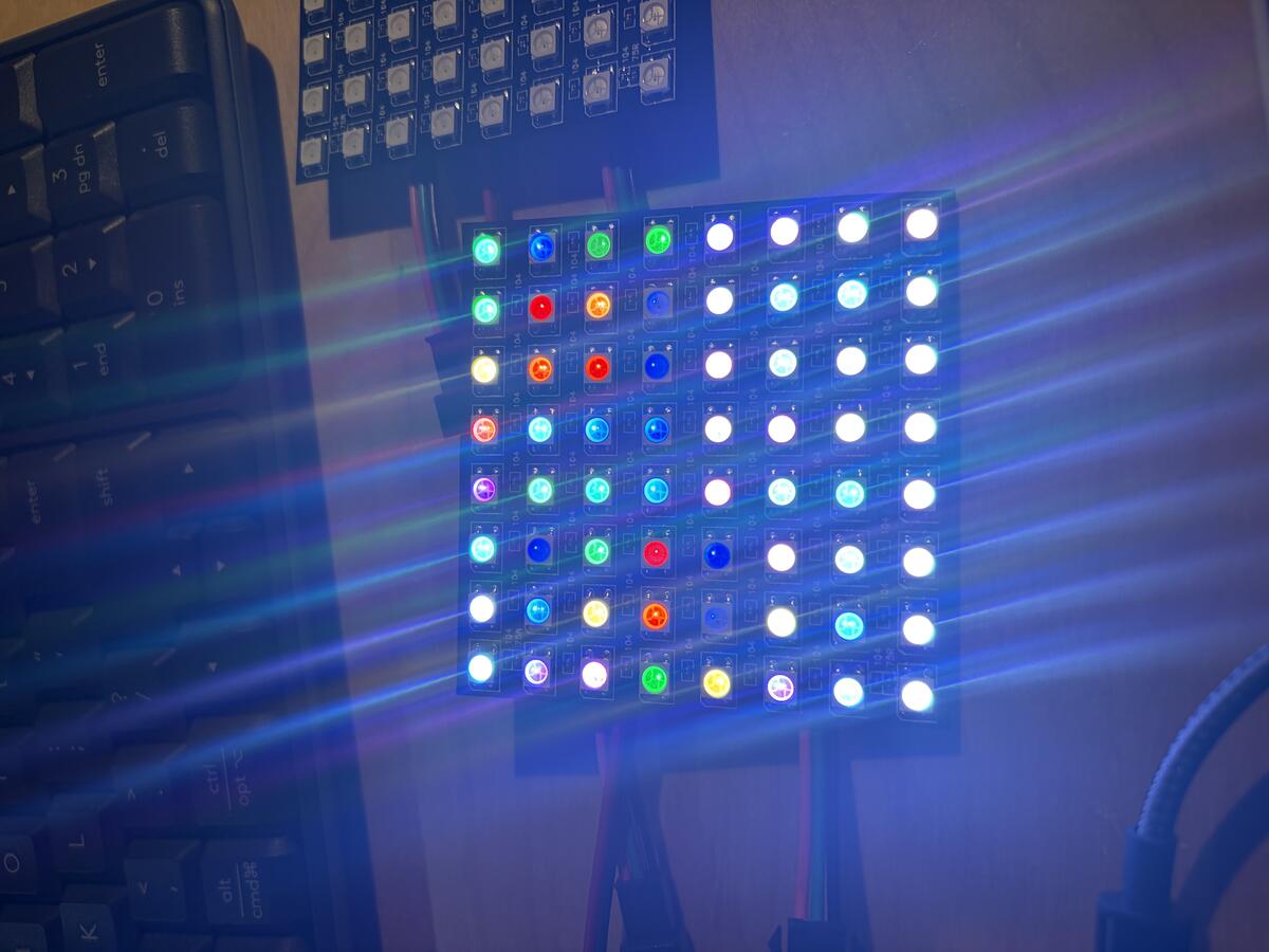
At first the LEDs would not light up in the correct sequence. I couldn't figure out why until I made multiple attempts.
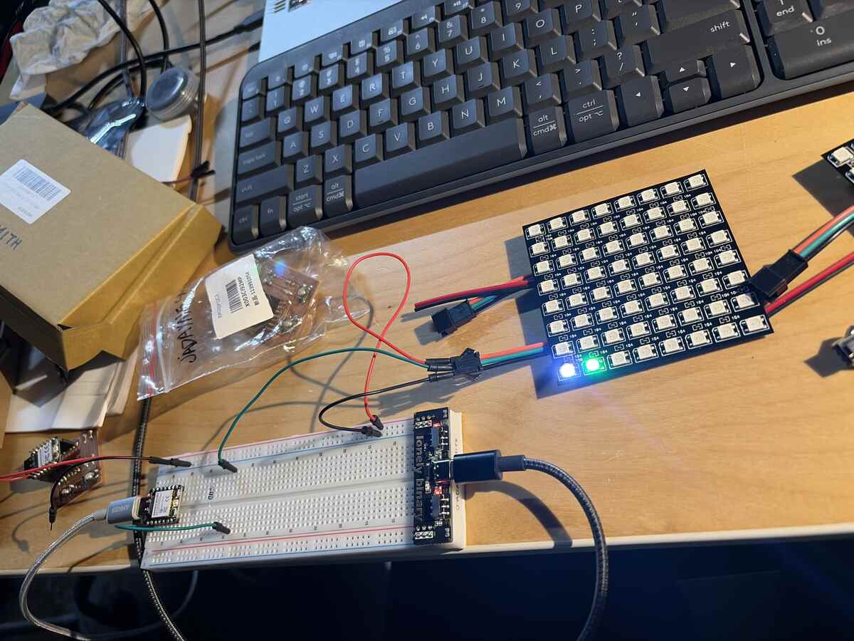
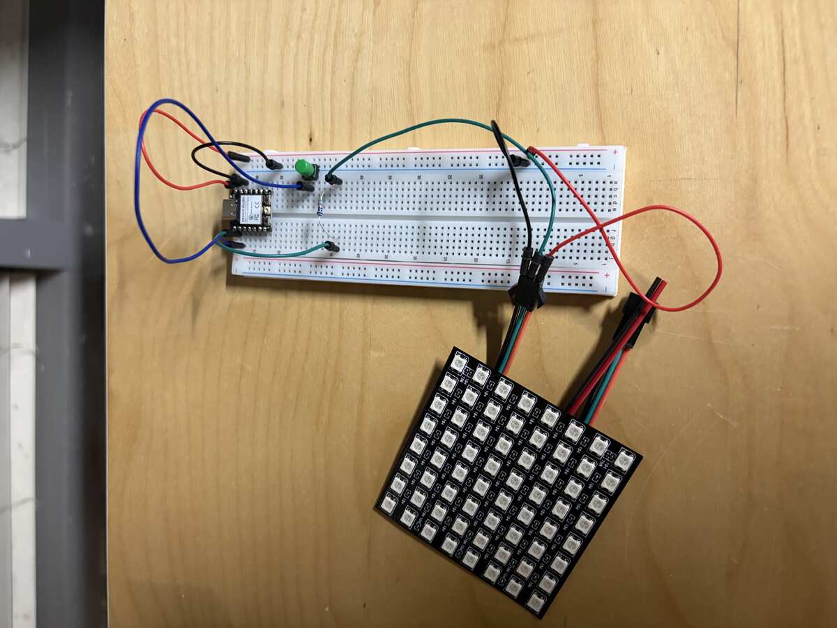
I continued to test the matrix on the breadboard just try to understand how the matrix works.
I tried isolating specific LEDs in the matrix to see if I could identify the issue.
The problem turned out to be that I needed to connect the ground of the power supply to the ground of the microcontroller. Until that point, I thought I needed to keep the microcontroller separate from the power supply to avoid burning the board. I know know that the board needs the components to be connected to ground. I also realized that I could power the microcontroller from the powersupply without using the embedded USB port.
The matrix was working and I used some sketch tissue to act as a diffuser.
PCB Design and Milling
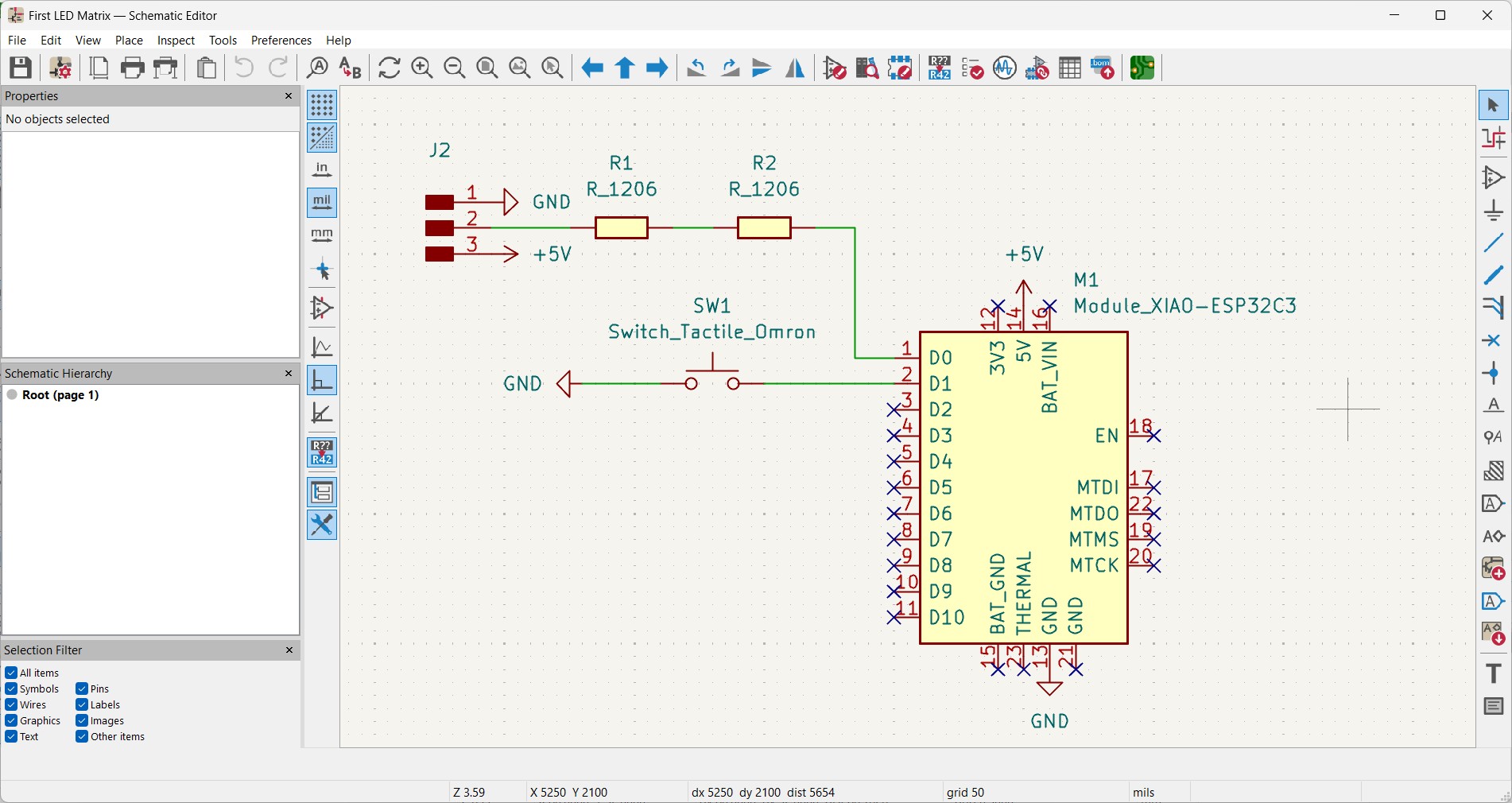
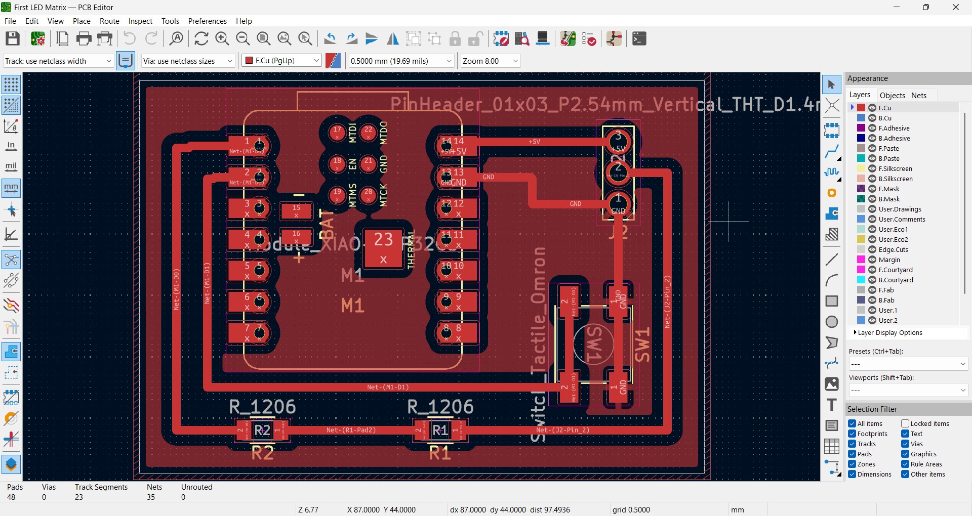
I designed the PCB in KiCad using a 3 pin connection for the LED matrix. The Seeed Xiao ESP32-C3 and surface mounted switchh symbols worked perfectly. I didn't need to install any new libraries.
I milled the PCB. It took some adjustments to get the depth right.
PCB assembled and ready for testing.
HELLO WORLD
I also had a button to start and stop the animation.
Group Project
For the group project I will be testing the power consumption of an Output Device.
Looking at the Ohms reading as the scolling text goes across the LEDs, I can see that the level of registered resistance is fluctuating. This could be an unstable connection but there aren't any issues with the displayed text. My assumption is that the signal might be drawing power at different rates and that might impact the reading.
The voltage reading is fluctuating much like what was seen in the resistance. It stays within a consistent range of .008-.011V when the red text is scolling but increases to .013-.015V when the blue text is scrolling. My concusion is that Blue LEDs draw more power than Red LEDs and the fluctuations may have been due to signal changes.
I discovered that setting the multimeter to Amps disrupts the signal on the LEDs but there is still a reading. The value is also fluctuating as the text scolls. My final conclusion is that the scrolling text is a caused by varying power levels across the LEDs. This changes with color of the LED lights as well. Red light requires less power than Blue light and the variations of power consumption also impacts the resistance reading.