

8. Electronics Production
This week I learned to prepare my PCB Gerber files for milling. I did it using KiCad, Bantam, and JLCPCB.
I used the PCB I designed in Week 6 for this week's assignment.
Week 8 Group AssignmentUsing JLCPCB
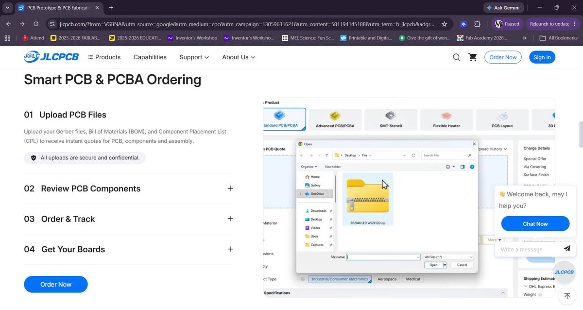
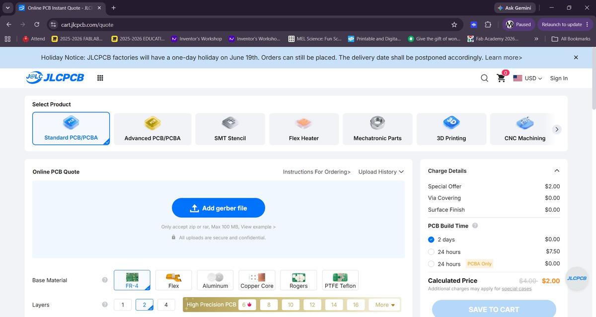
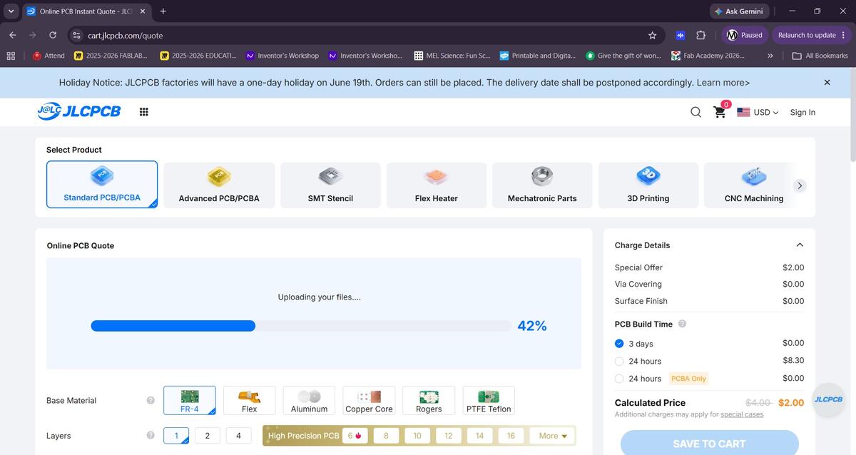
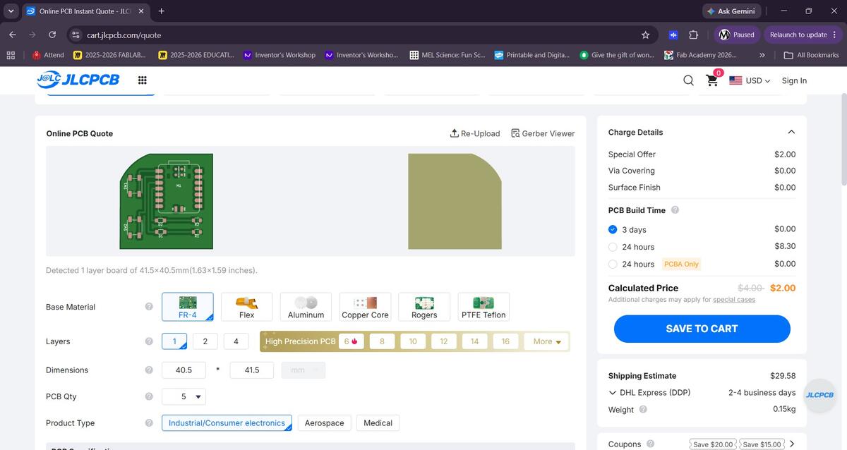
Using the PCB I designed in the previous weeks, I went through the prcosees of setting up an order through JLCPCB. It was very easy once I realized I would need to compress all of my Gerber files into a ZIP folder in order to upload them. I selected the single sided FR-4 PCB, which I would not mill inhouse, in a green color. The minimum order quantity is 5 and the total came up to $29.58 with a 2-4 businessday shipping time. Fulfillment would be done by DHL Express.
Using Bantam
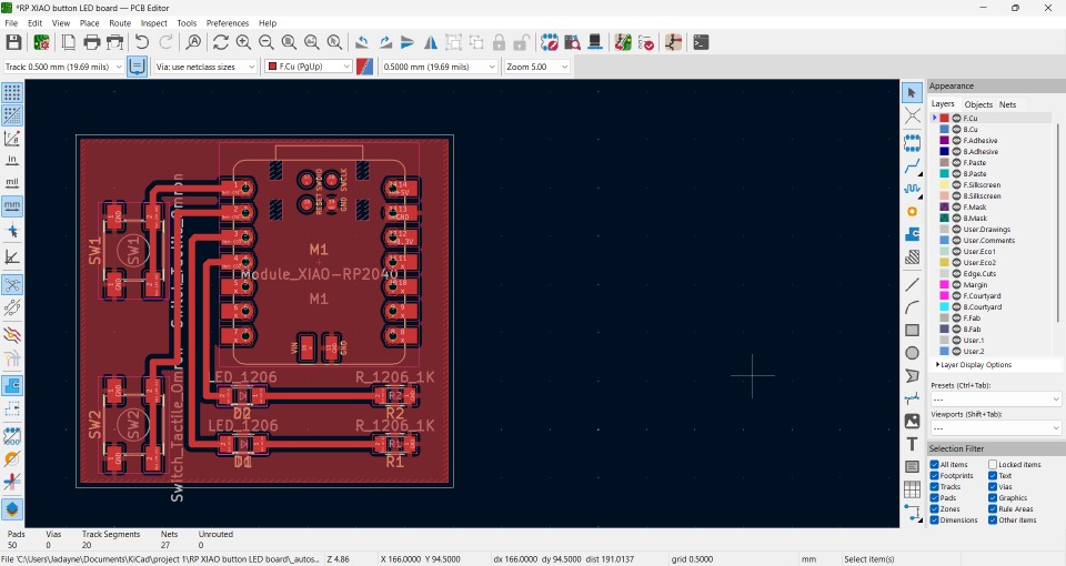
I returned to KiCad to create a proper schematic of the PBC. I still wasn’t fully confident but I followed the logic of how electric currents flow. My logic may have been a little off because I still think I put the resistors in the wrong place.
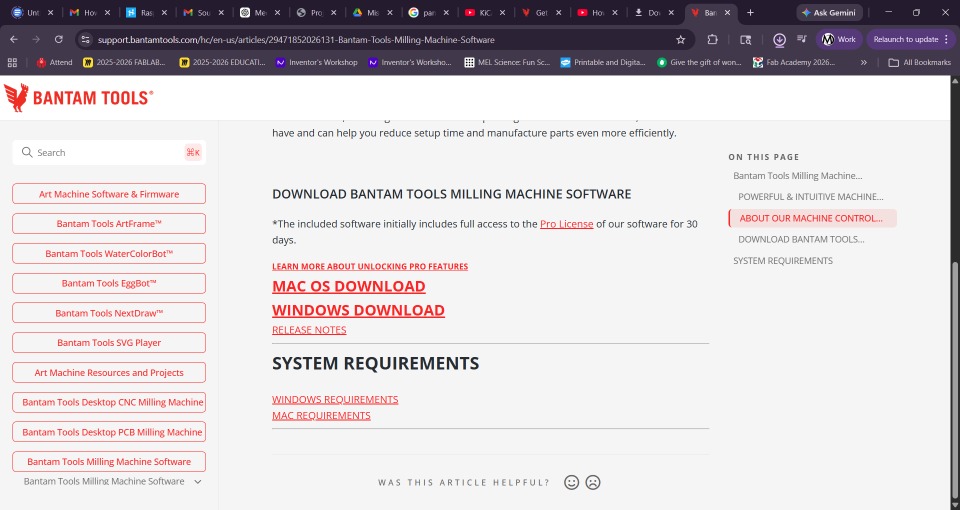
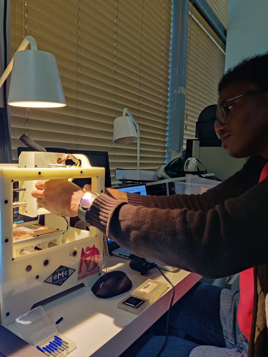
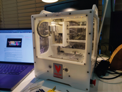
We use Bantam milling tools at Moonlighter FabLab to produce our PCBs. To use these tools I needed to install the desktop application for my Windows pc.
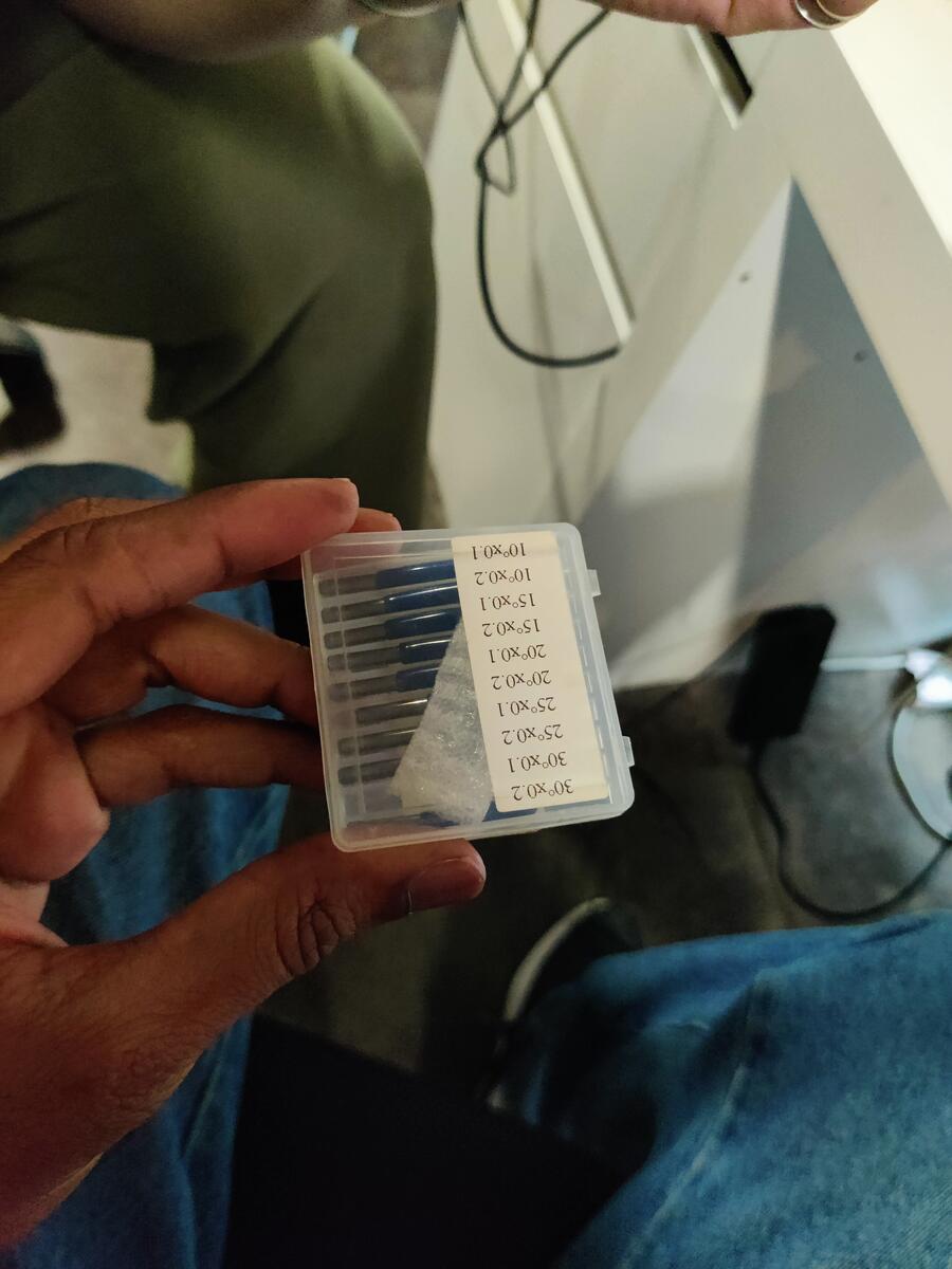
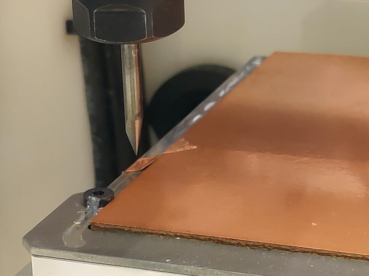
I found these bits for the mill thinking they were the correct type for PCBs.
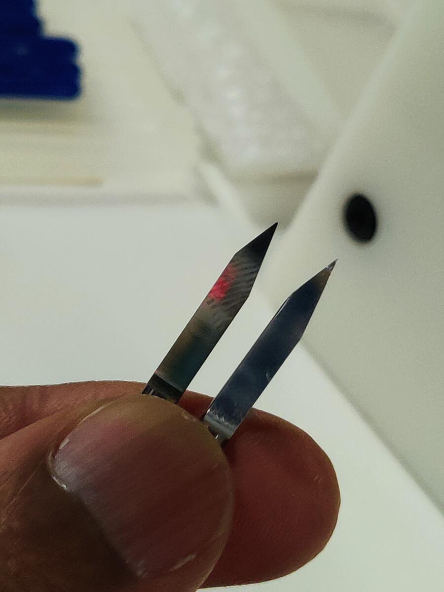
You can see how sharp and pointed the tips are.
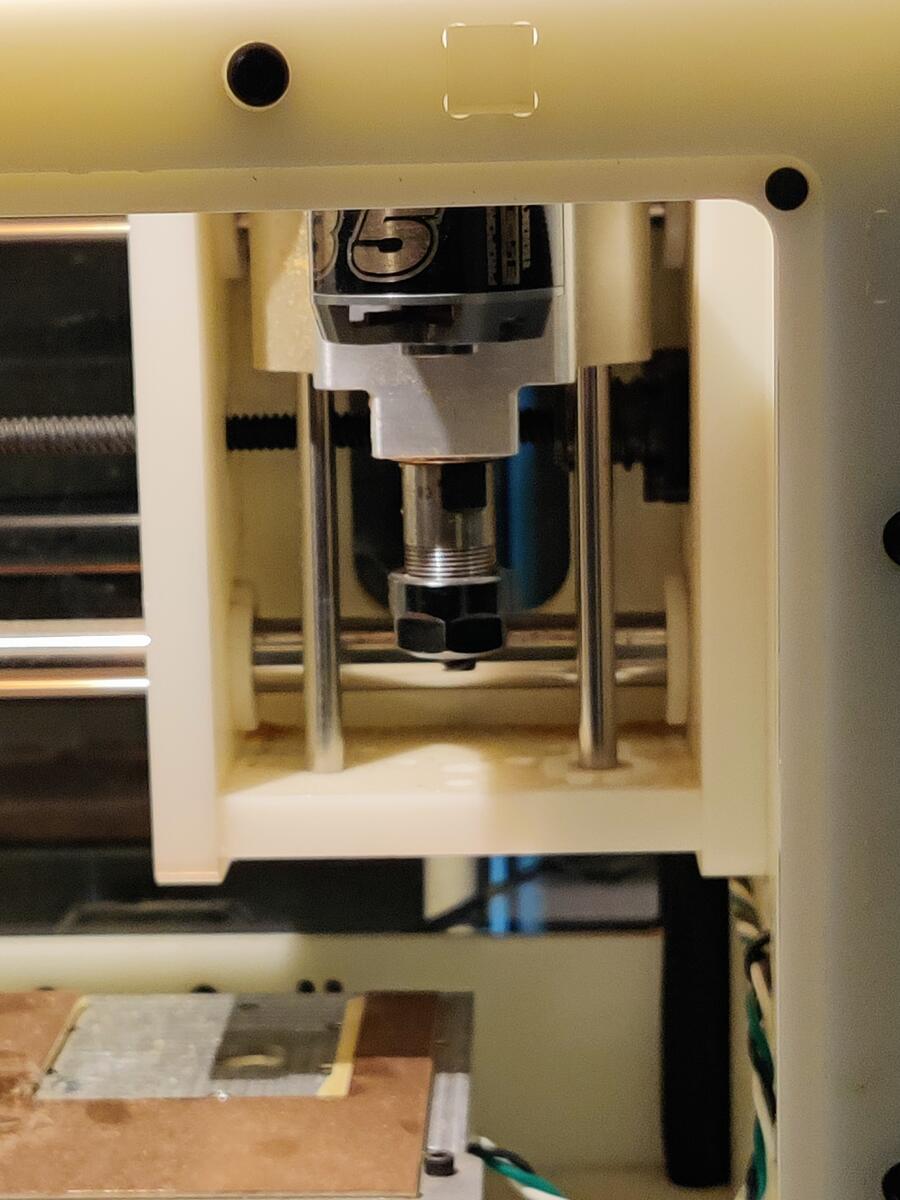
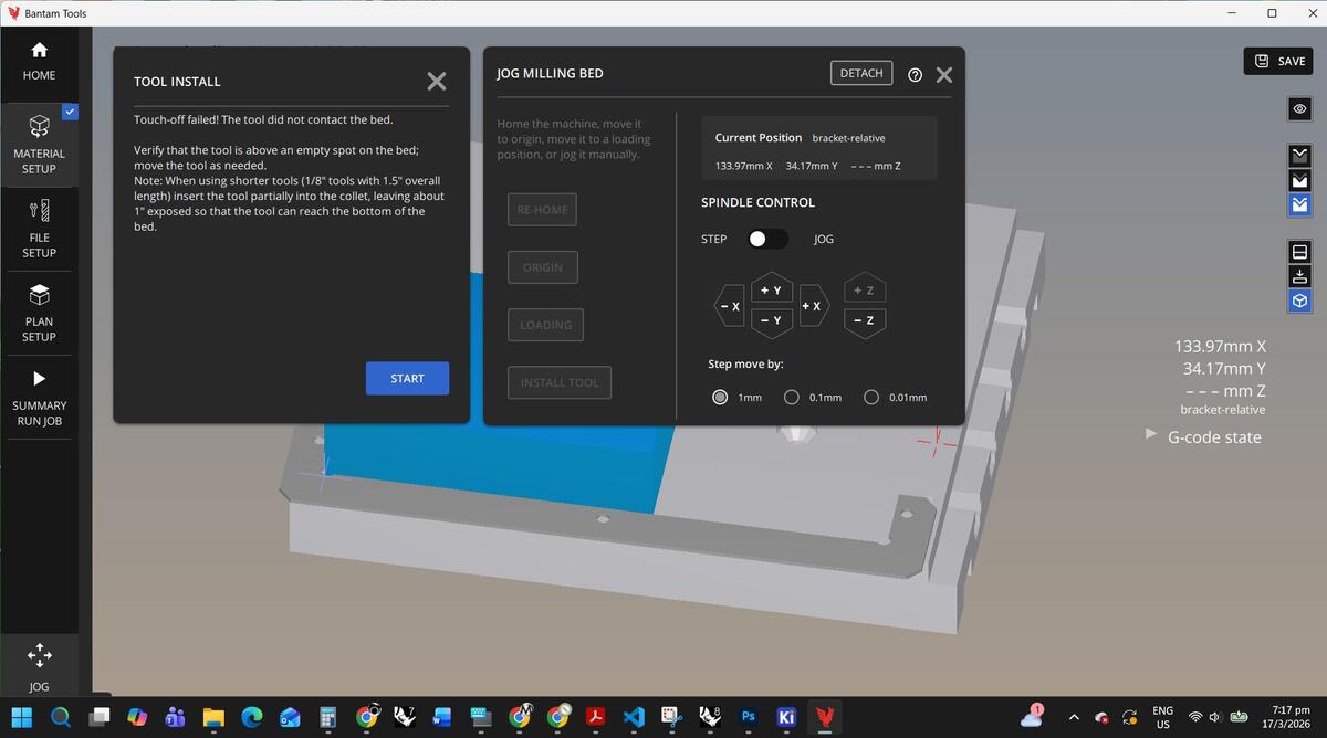
Next I had to prepare the Bantam
I loaded the bit by loosening the grommet and inserting it according to the instruction in the application.
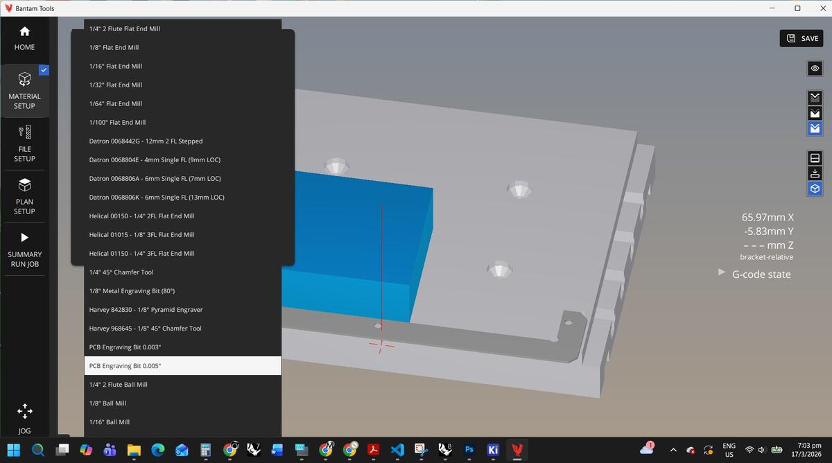
Then I set up the interface for the bit type, material and positioning.
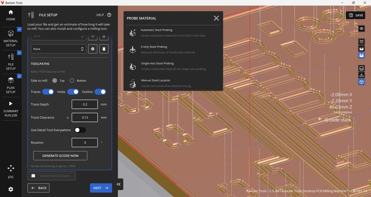
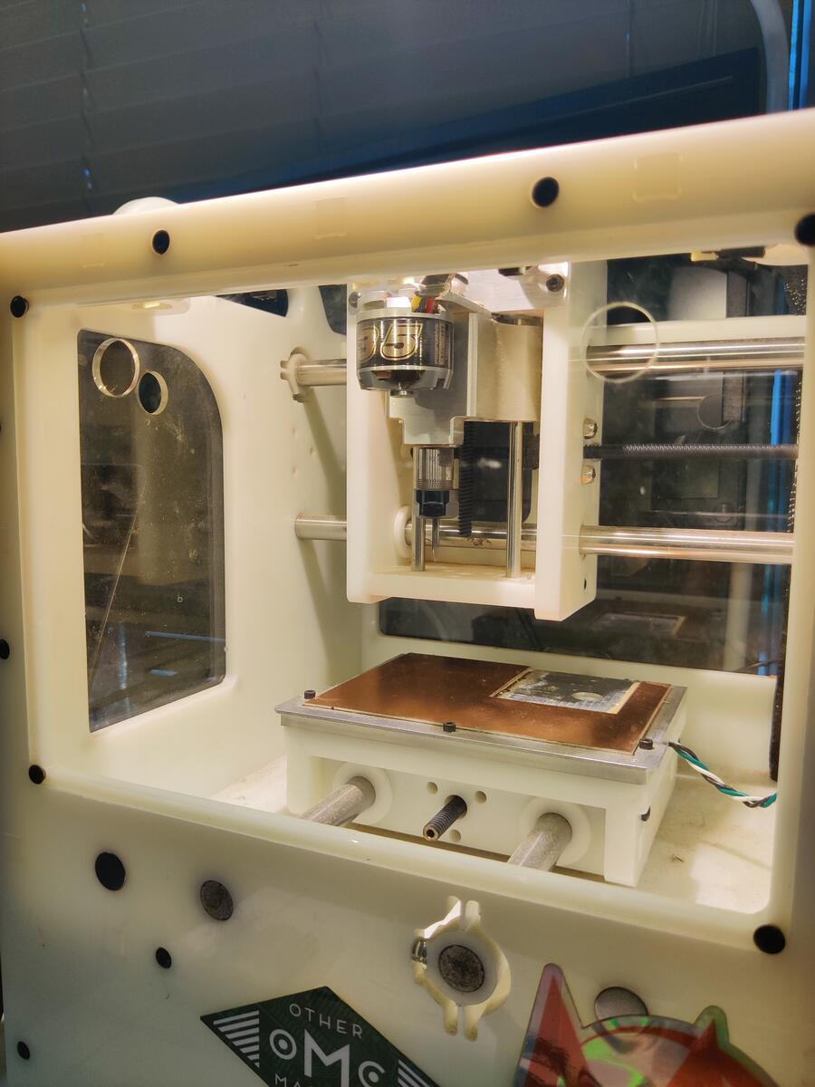
After uploading the Gerber file of my PCB from KiCad, I was able to place it on the material for the best layout to be cut.

This took some trial and error as I was figuring it out for the first time.
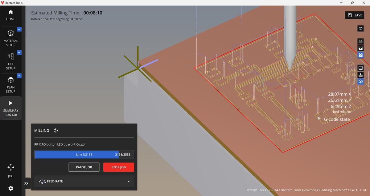
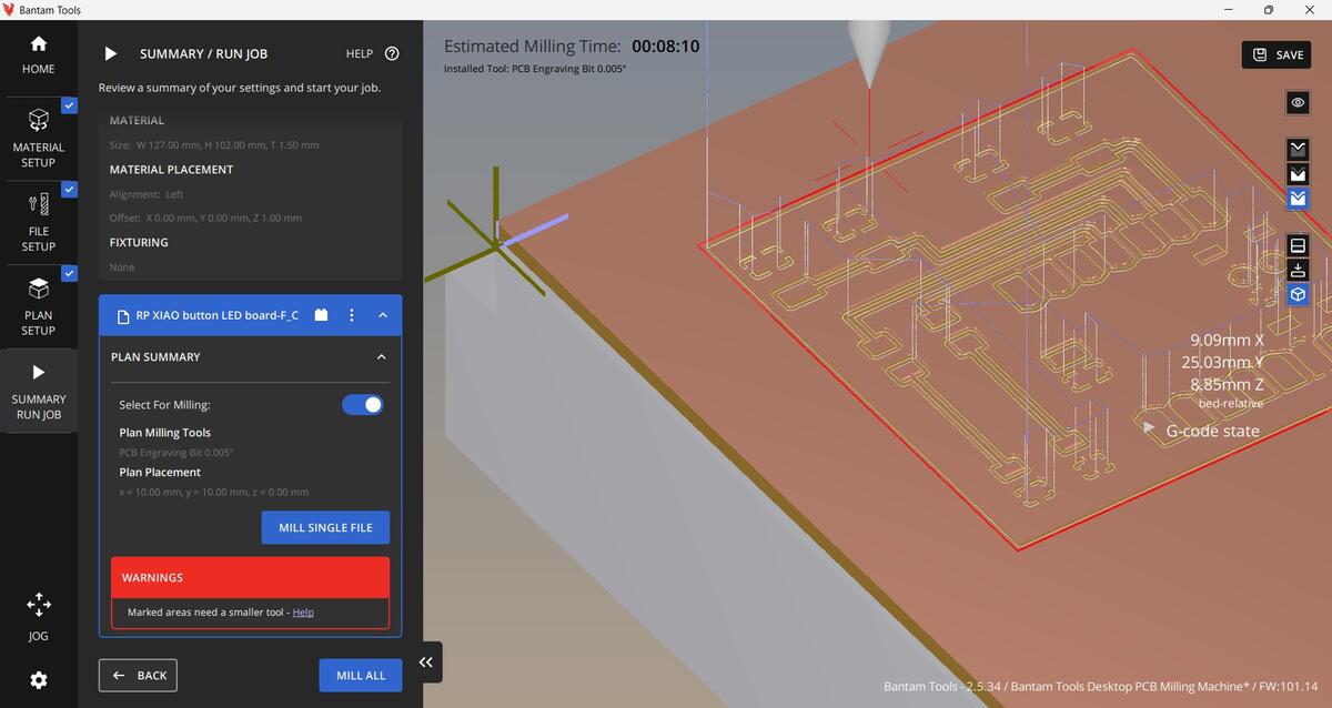
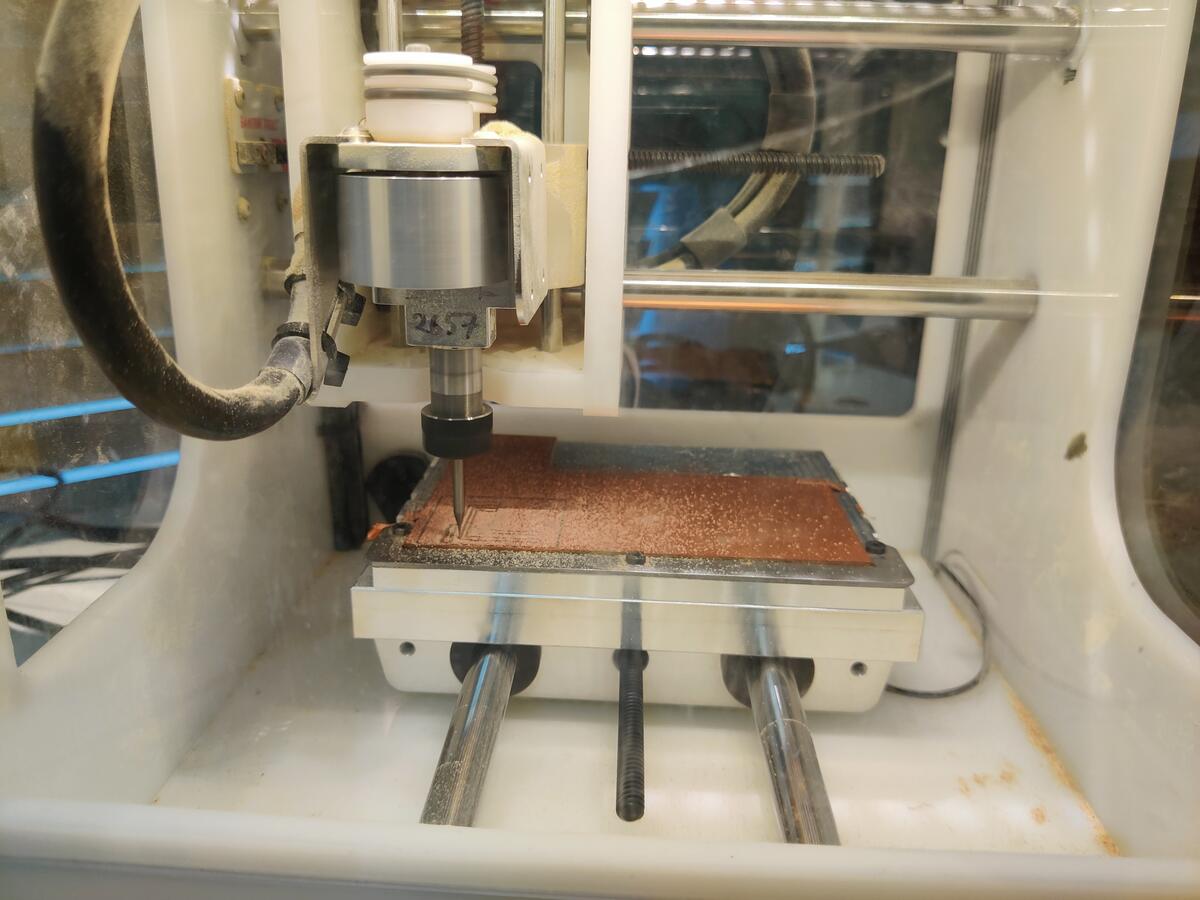
It was finally time to cut my first PBC. The program tracks the mill as it follows the tool path.

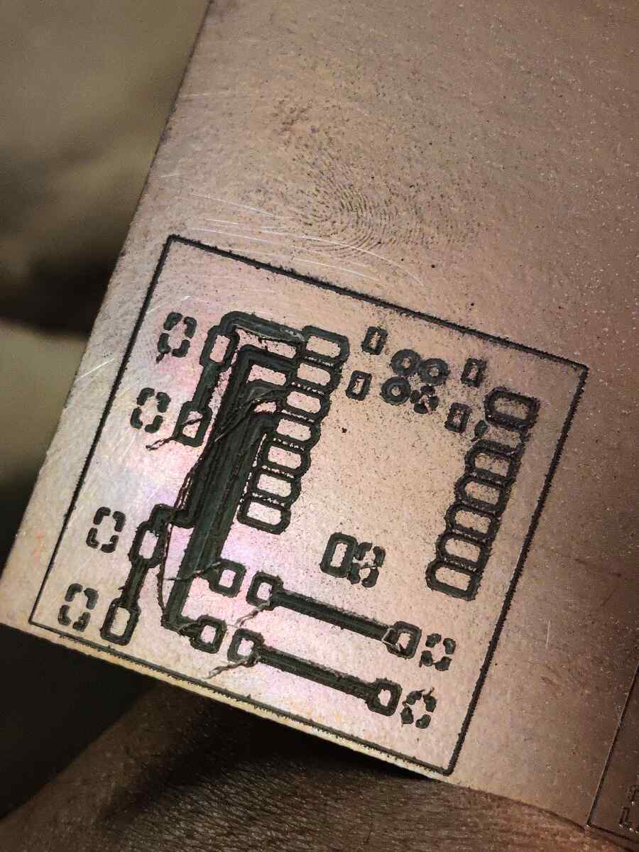
The first cut failed because the traces were too thin which caused them to fray. The bit I used was also unable to cut the PCB out fully.
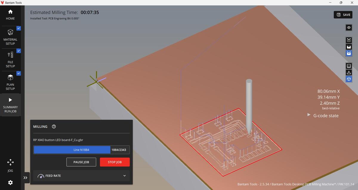
I went back to KiCad to increase the trace thickness and uploaded it to Bantam.
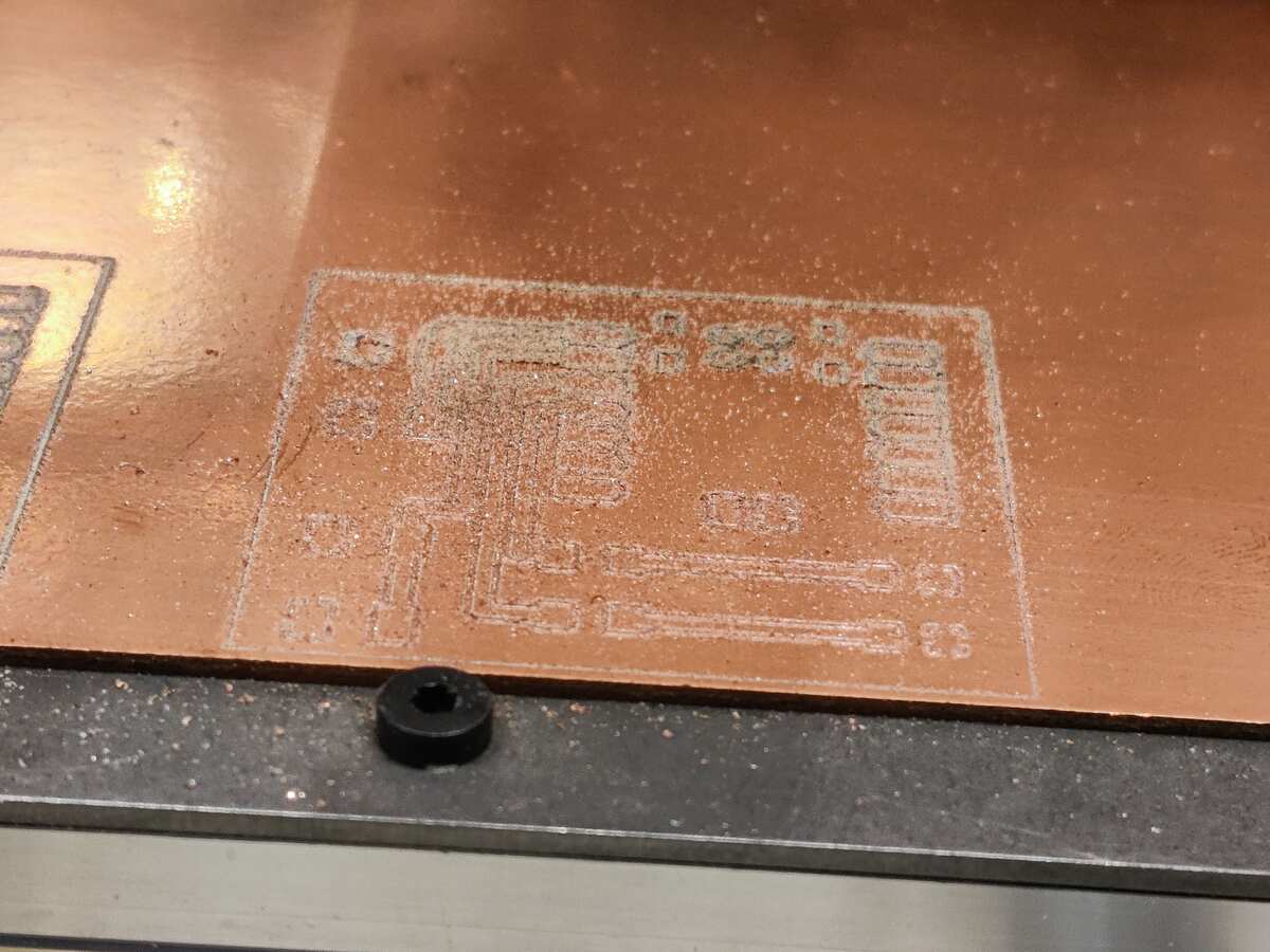
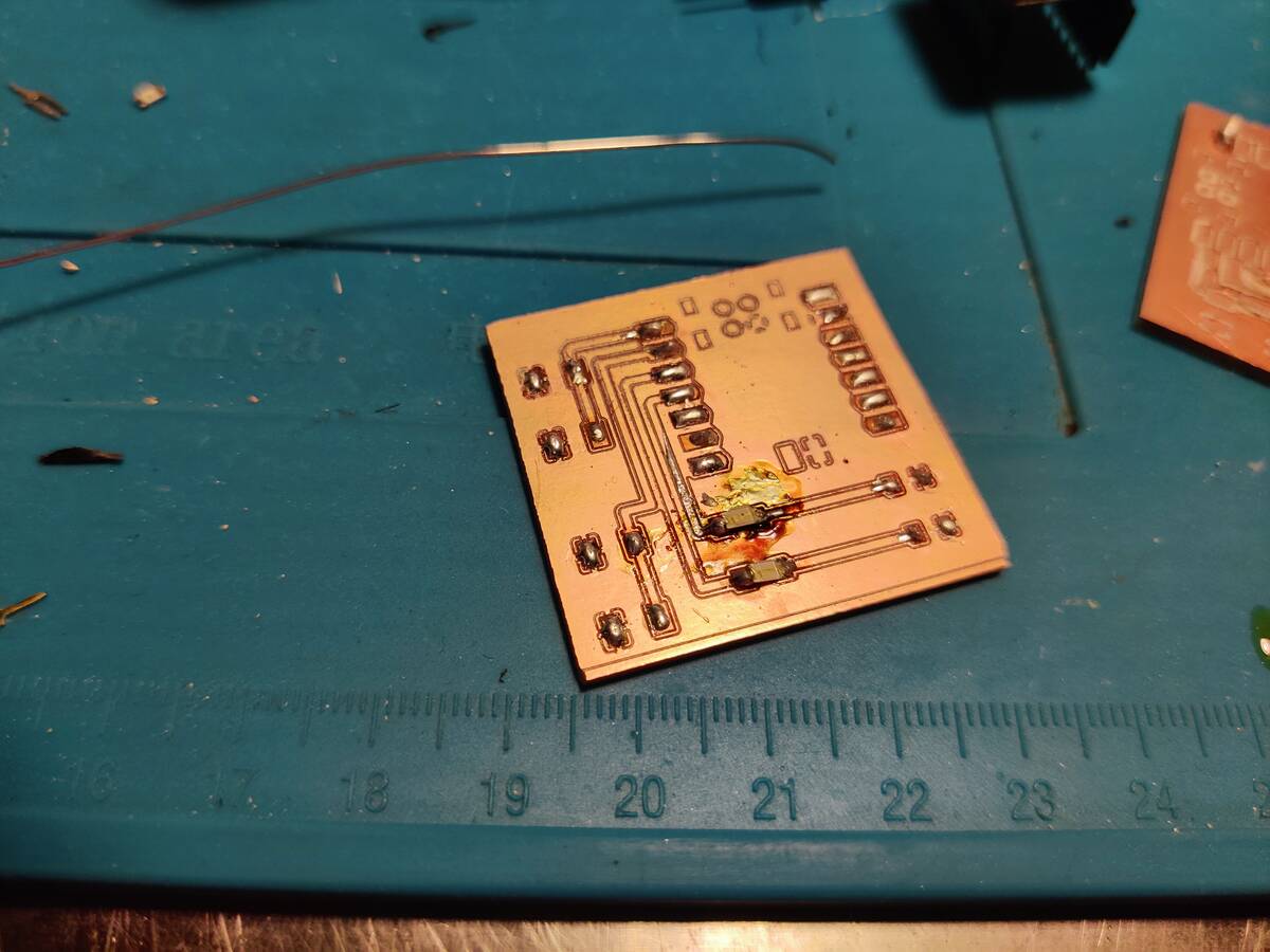
This cut went much better but still was not able to be cut out completely.
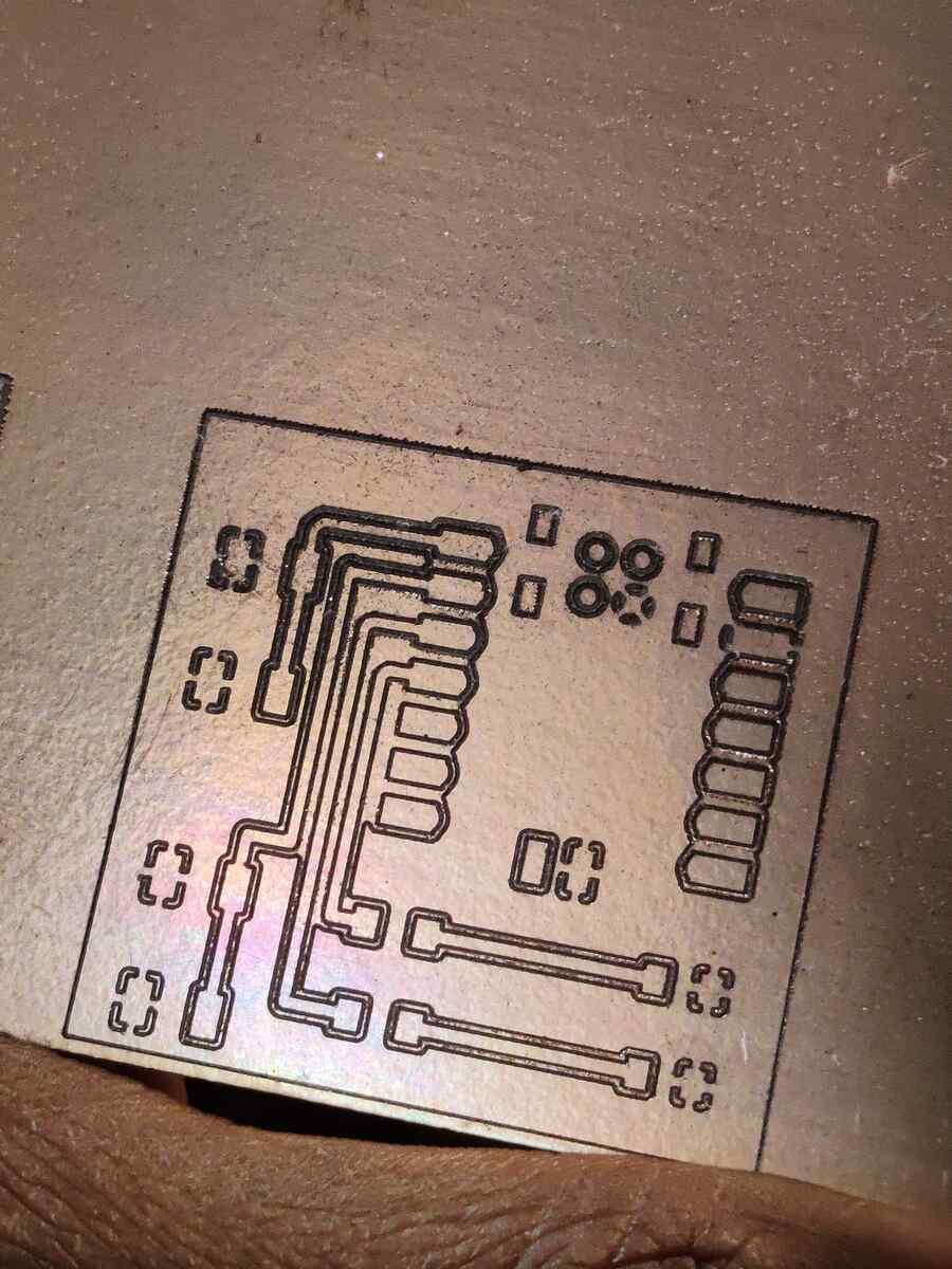
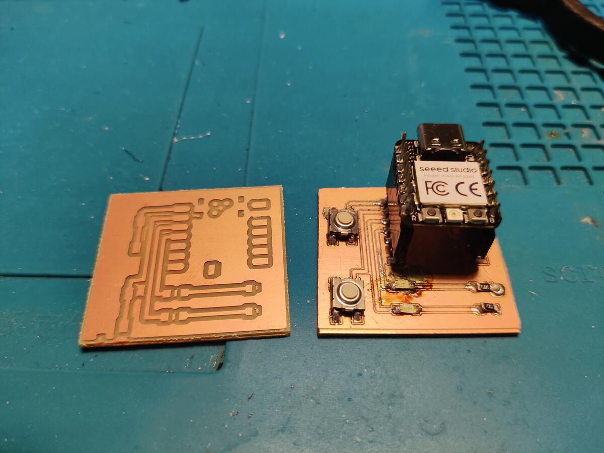
Here you can see the difference between the cuts.

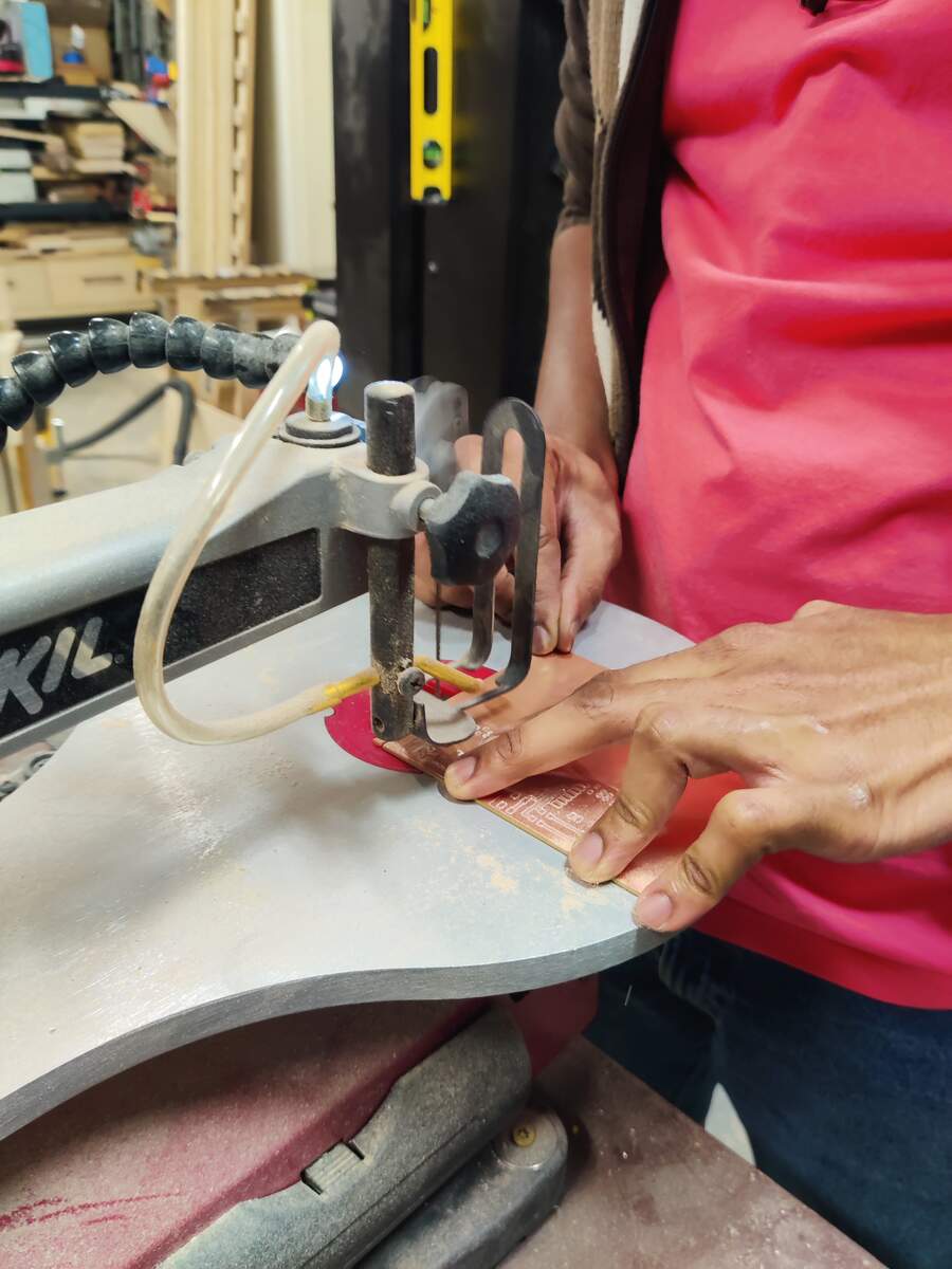
I used a scroll saw to finish cutting the boards out.
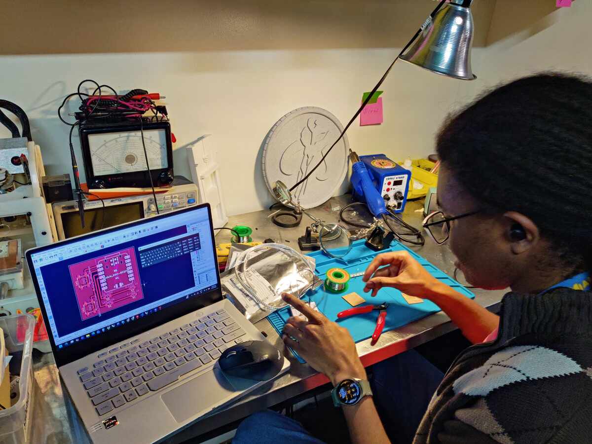
I used the KiCad design to solder the second board.
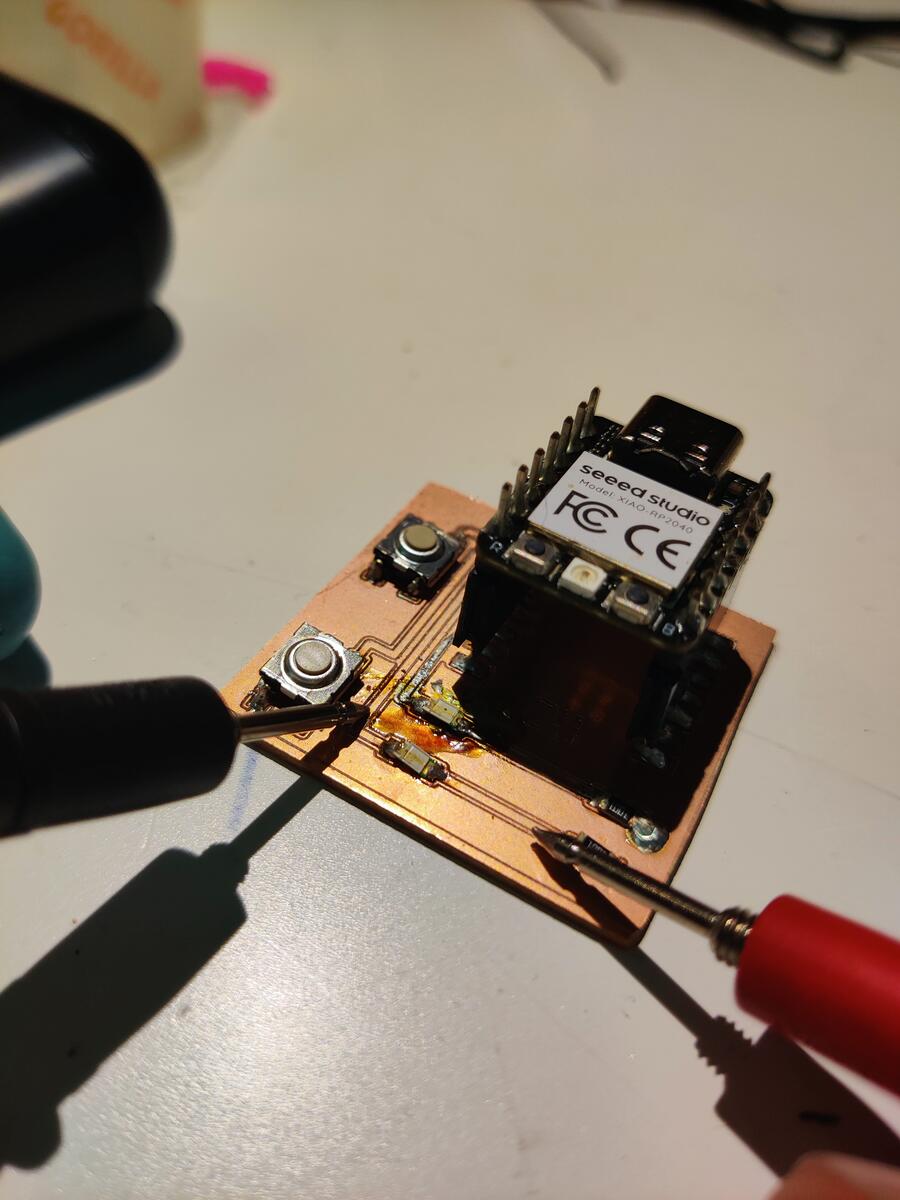
Using a Multimeter, I tested the traces because the board did not work.
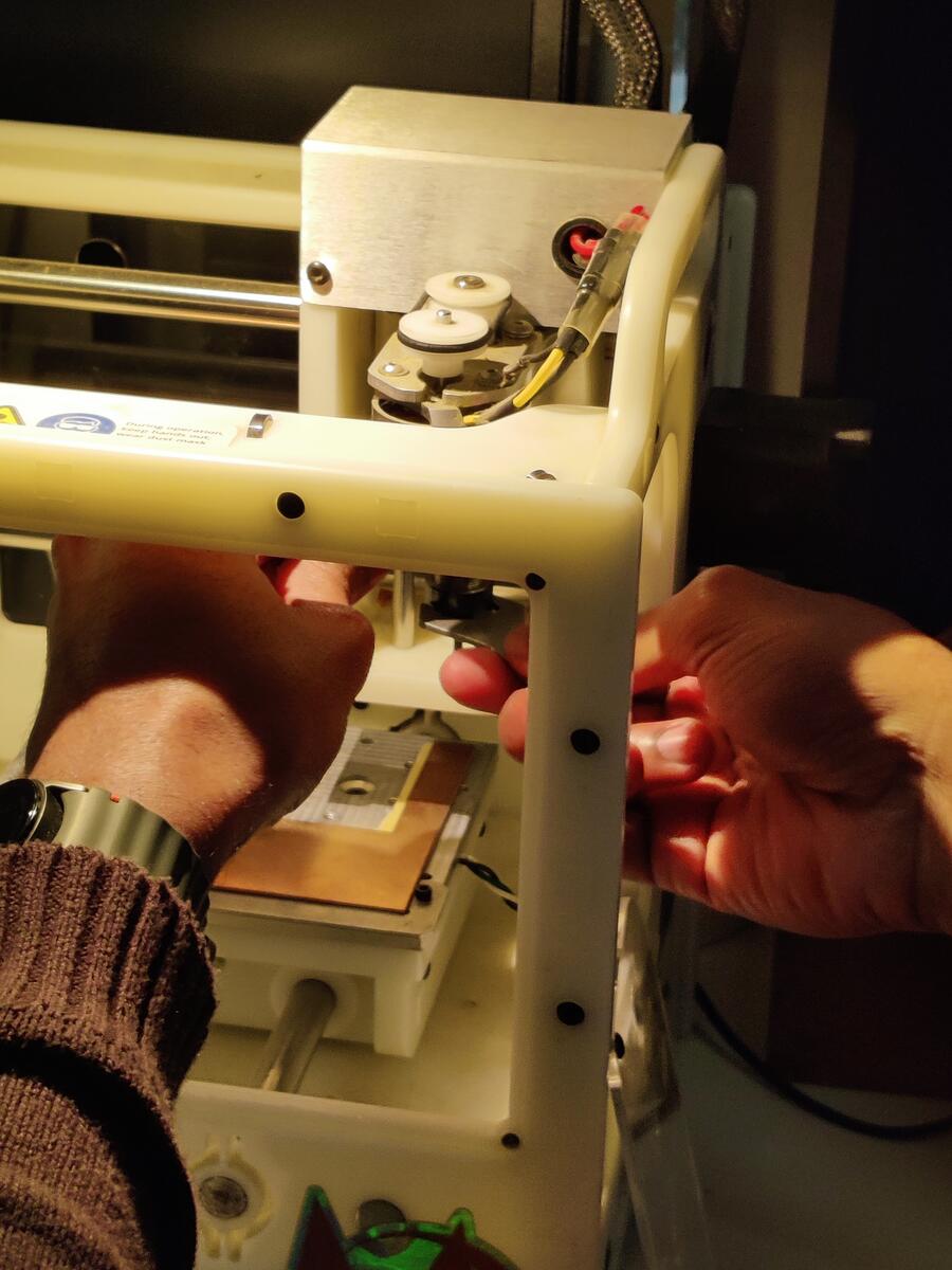
Resetting for another attempt, I found out that I was using the wrong Bantam and the wrong bit.
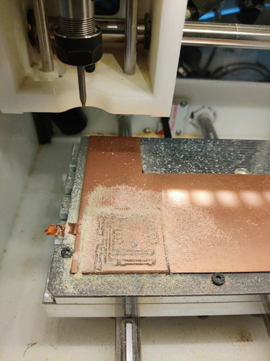
Setting up the new Bantam Tool with a 1/32” flat end mill worked much better.
The final cuts were clean and had wider clearances. This flat end mill was also able to cut through the board eliminating the need to do post processing.
The difference between the boards was very clear as the thicker clearances made the PCB look much cleaner.
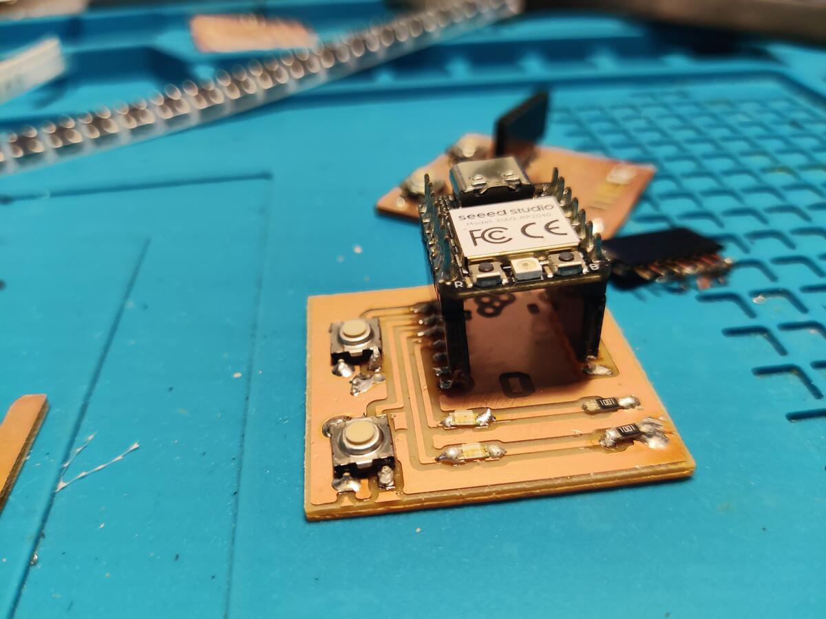
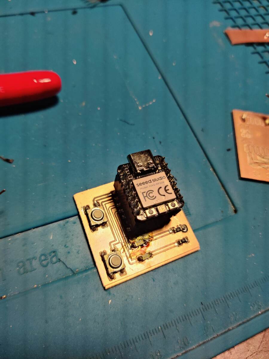
Soldering the final board was much easier and went very quickly.
Here you can see the working final product.
Code for the Final Product
from machine import Pin
import time

ledRed = Pin(28, Pin.OUT)
ledGreen = Pin(29, Pin.OUT)
buttonRed = Pin(26, Pin.IN, Pin.PULL_UP)
buttonGreen = Pin(27, Pin.IN, Pin.PULL_UP)

while True:
    if buttonRed.value() == 0:
        ledRed.value(1)
    elif buttonGreen.value() == 0:
        ledGreen.value(1)
    else:
        ledRed.value(0)
        ledGreen.value(0)
    time.sleep(0.1)


'''Counter = 0
Fun_Num = 0

def fun(tim):
    global Counter
    Counter = Counter + 1
    print(Counter)
    ledRed.value(Counter%2)
    ledGreen.value(Counter%2-1)

tim = Timer(-1)
tim.init(period=1000, mode=Timer.PERIODIC, callback=fun)'''