Overview
This week's assignment asked me to design and document the system integration for my final project.
My final project is Loco Pik, a small emotional desktop companion robot. Loco Pik reacts through light, sound, movement, and AI voice interaction. In earlier weeks, I tested these functions as separate experiments. This week, I focused on making those functions work as one compact and stable object.
The main challenge was not a single module. The real challenge was the whole body. I needed to fit the shell, servos, speaker, LED, battery, control electronics, and sensors into one small robot. I also needed to keep the robot testable and repairable.
Assignment
The individual assignment asked me to design and document the system integration for my final project.
For Loco Pik, I documented the integration plan, CAD evidence, sketch evidence, packaging method, and internal assembly logic. I also documented tests that show the robot working as one complete system.
Checklist
| Status | Checklist item | Evidence on this page |
|---|---|---|
| Yes | Made a plan for system integration for the final project. | The overview, packaging strategy, assembly logic, test evidence, and failure mode reflection document my integration plan. |
| Yes | Documented the plan with CAD and/or sketches for system integration. | The CAD and Sketch Documentation section includes my hand-drawn system sketch, exploded CAD overview, first printed assembly set, layer planning images, and final layer design images. |
| Yes | Implemented methods of packaging. | The layered packaging strategy shows how I arranged, stacked, and enclosed the internal parts inside the body. |
| Yes | Designed the final project to look like a finished product. | The packaging strategy hides most electronics inside the shell. It also supports a compact, rounded, and integrated appearance. |
| Yes | Documented system integration of the final project. | This page documents the relationships between the shell, structural layers, electronics, power, motion, light, sound, and AI interaction. |
| Pending | Linked to this system integration documentation from the final project page. |
I will complete this after I add a direct link from
final-project.html to week15.html.
|
CAD and Sketch Documentation
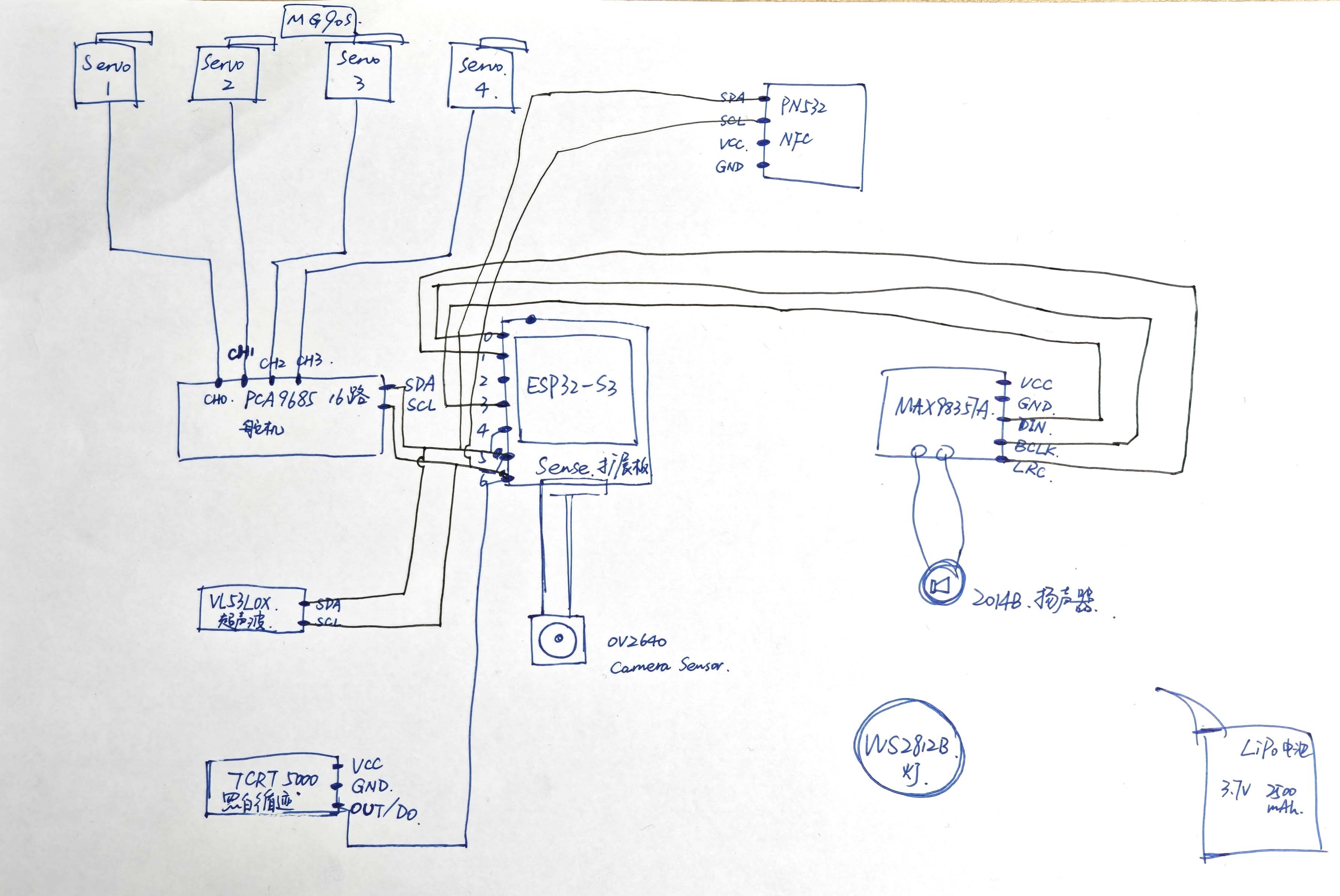
I first mapped the system as a hand-drawn diagram. This diagram helped me study the relationship between the controller, servo driver, four servos, amplifier, speaker, LED, camera, ToF sensor, NFC, and battery. I used it before deciding the final internal layout.
System integration sketch
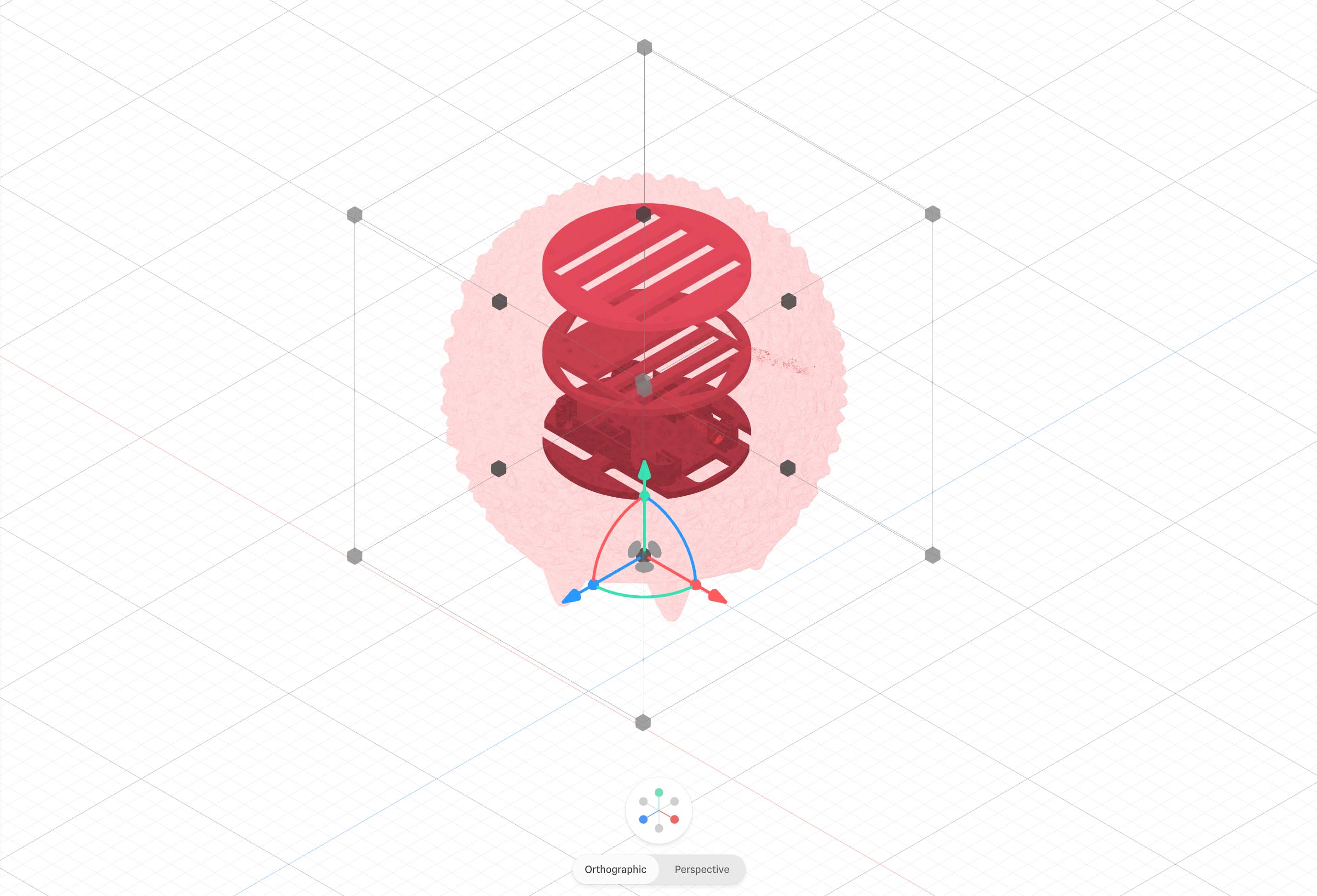
After I sketched the system map, I translated the idea into CAD. The exploded overview helped me see the shell and internal layers as one stacked structure. It also helped me avoid treating the modules as loose parts.
Exploded CAD overview
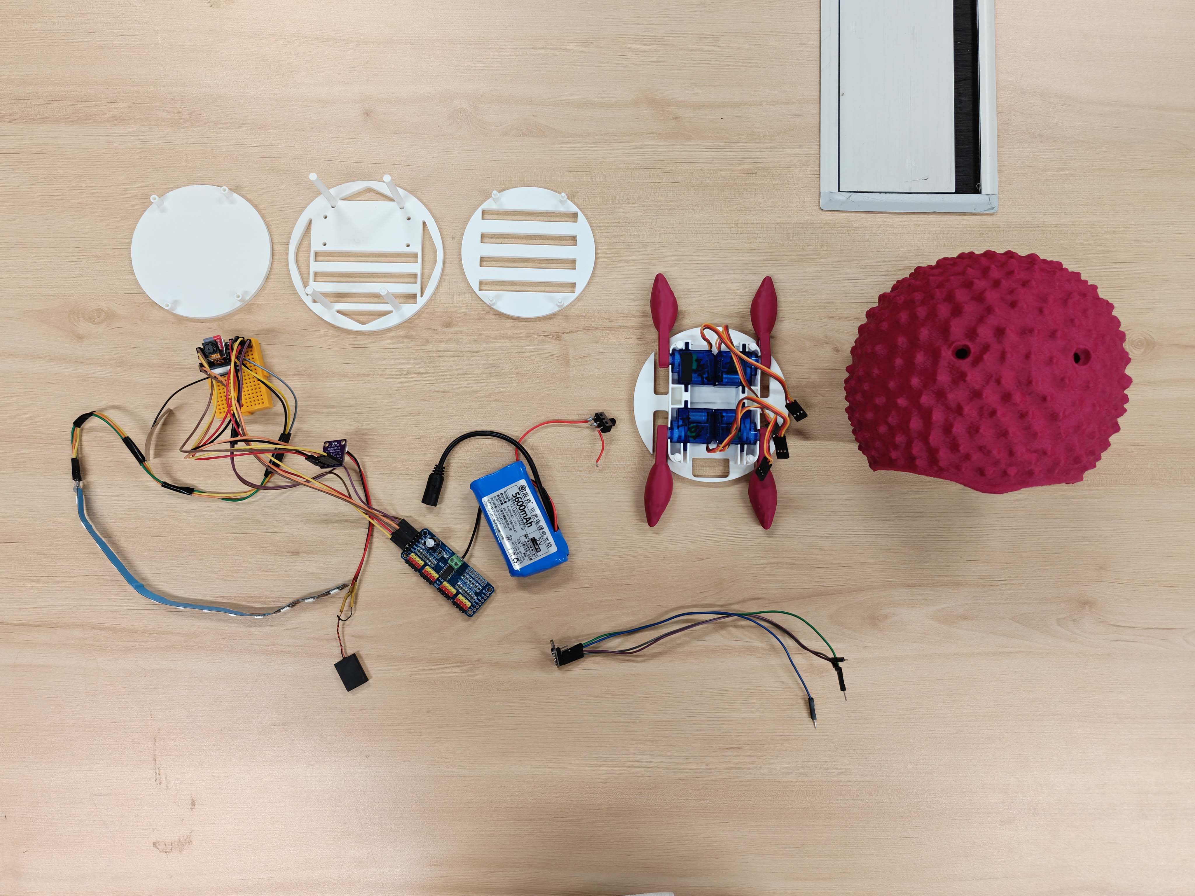
First printed assembly set
Layered Packaging Strategy
I divided the internal structure into three functional levels. This made the system easier to understand and assemble. For each level, I first made a component planning diagram. I then developed the final structural design. This process helped me move from planning to a more manufacturable packaging solution.
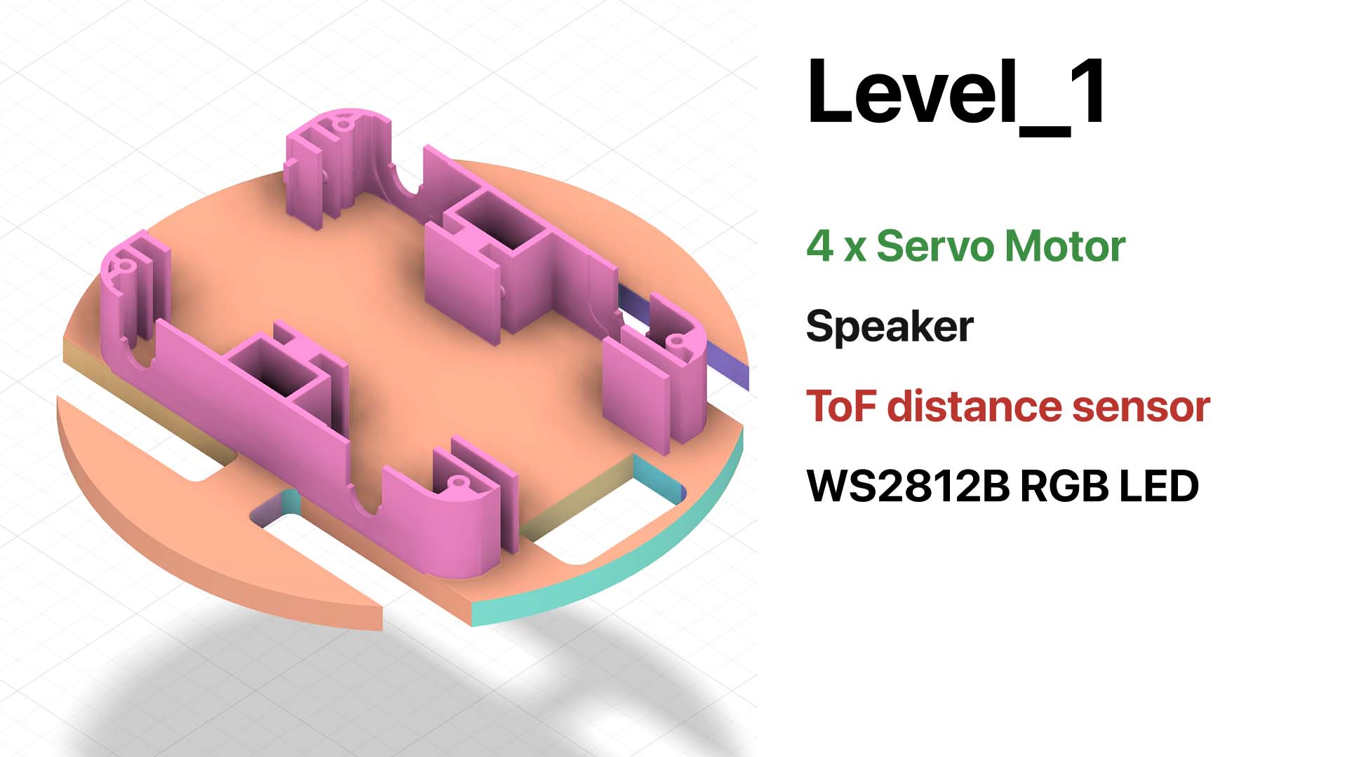
Level 1 — component planning
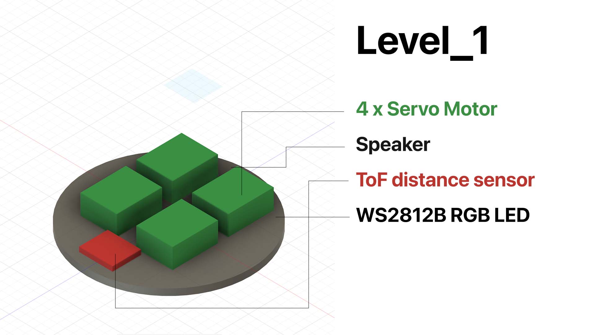
This image shows the planned component allocation for Level 1. I used this diagram to decide which parts belonged in the lowest layer. Level 1 handles movement, sound output, distance sensing, and bottom light feedback.
Level 1 — final layer design
After I defined the component allocation, I developed the final structure for Level 1. This layer includes the mounting logic for the servo motors. It also holds the speaker, ToF sensor, and LED. Level 1 forms the lower functional platform of the robot.
Level 2 — component planning
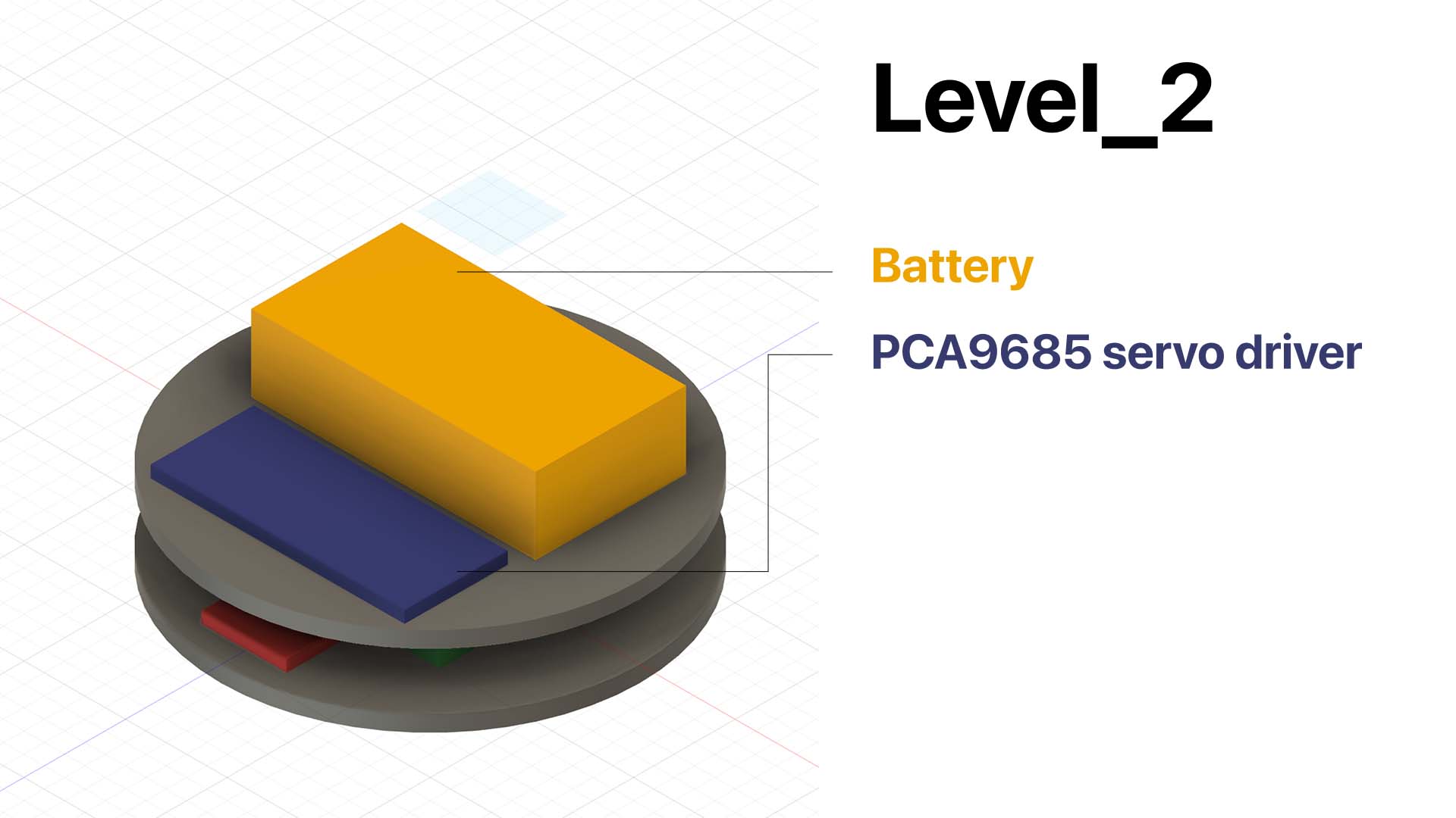
This image shows the planned component allocation for Level 2. I placed the battery and PCA9685 servo driver in the middle layer. This placement keeps power distribution and servo control clear between the lower and upper layers.
Level 2 — final layer design
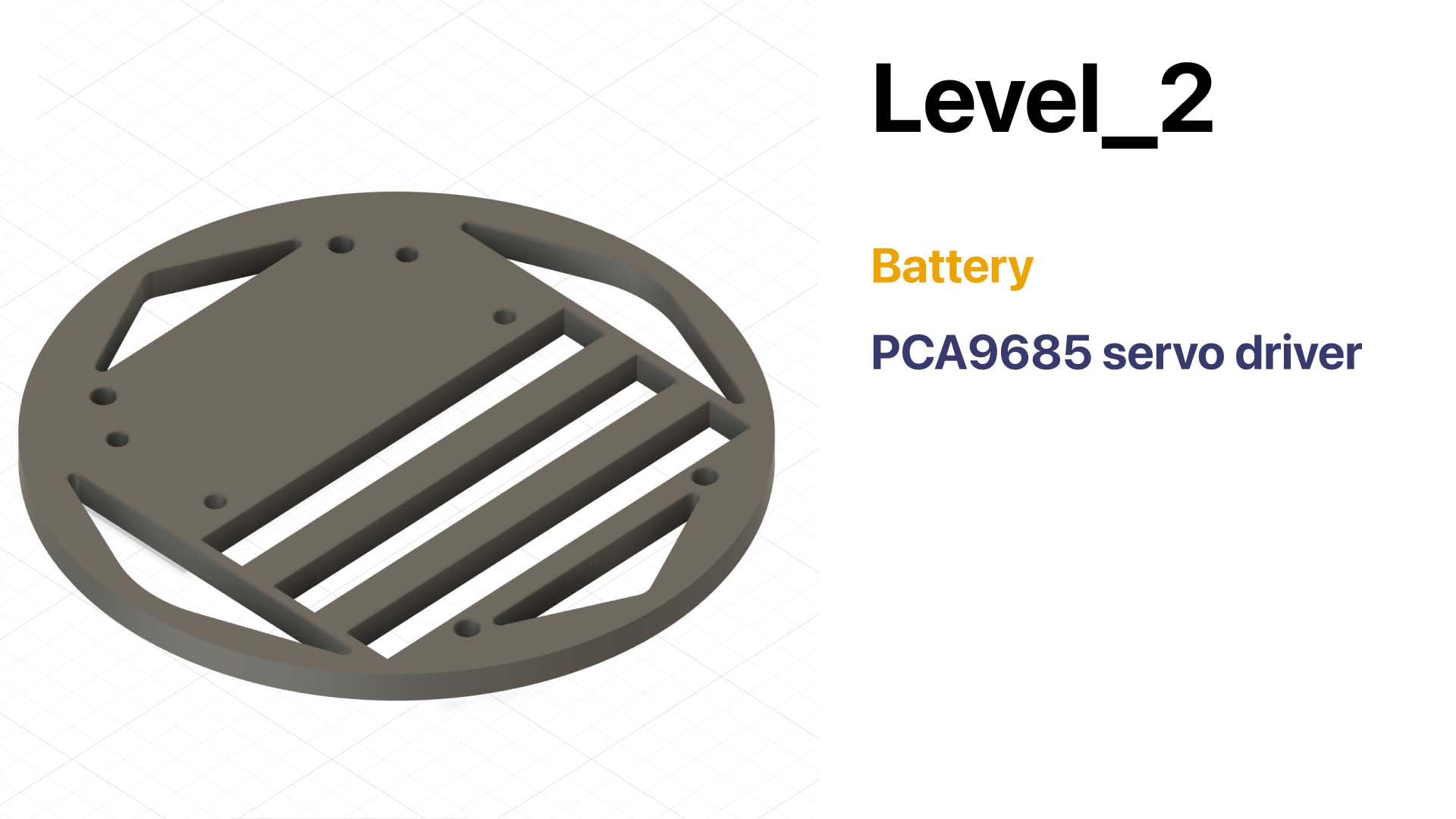
After component planning, I designed the final structure for Level 2. This layer supports power and actuation. It provides space for the battery and servo driver. It also separates the lower motion layer from the upper control layer.
Level 3 — component planning
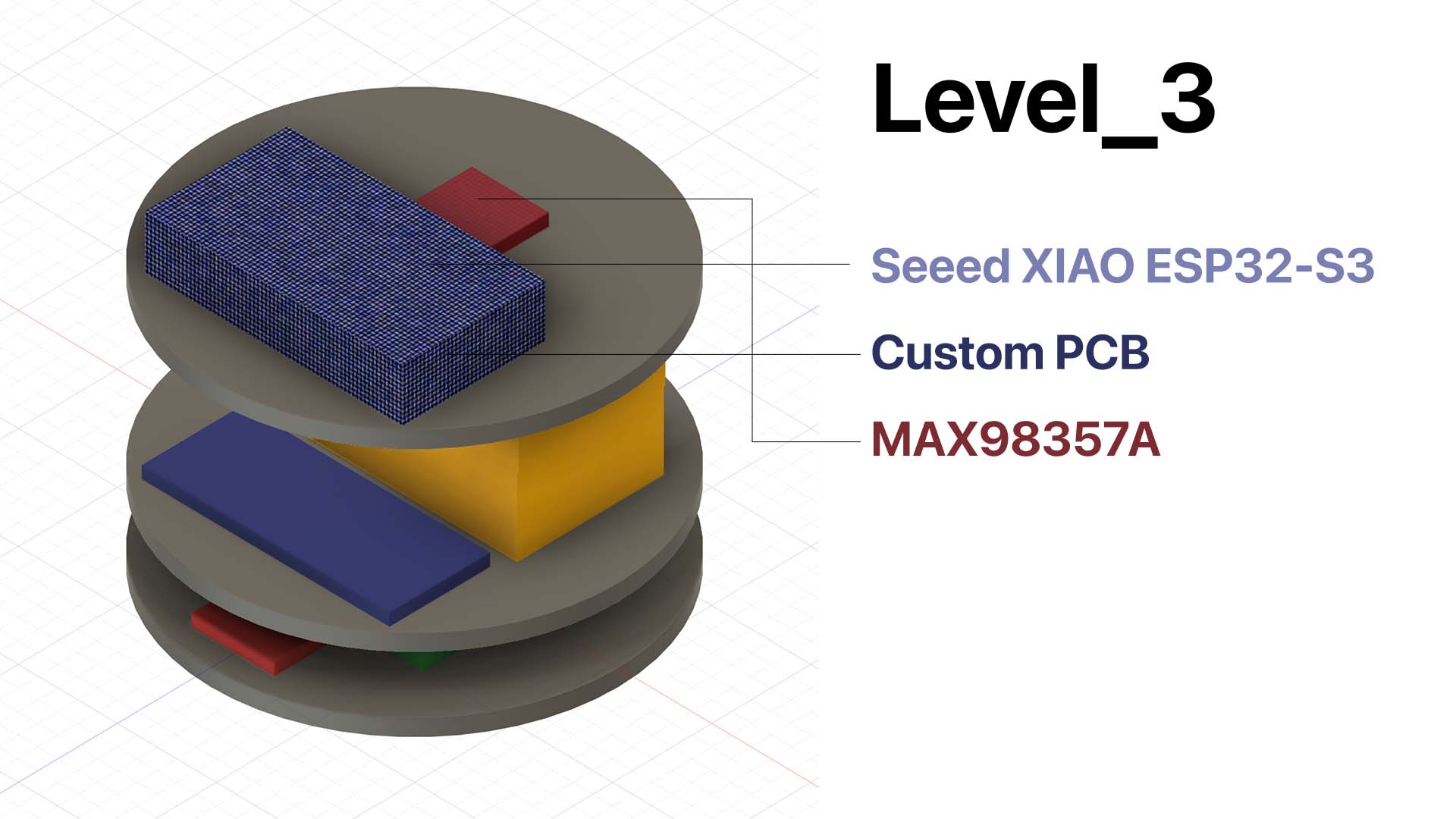
This image shows the planned component allocation for Level 3. I placed the main control electronics in the upper layer. This position makes programming, wiring, and debugging more accessible.
Level 3 — final layer design
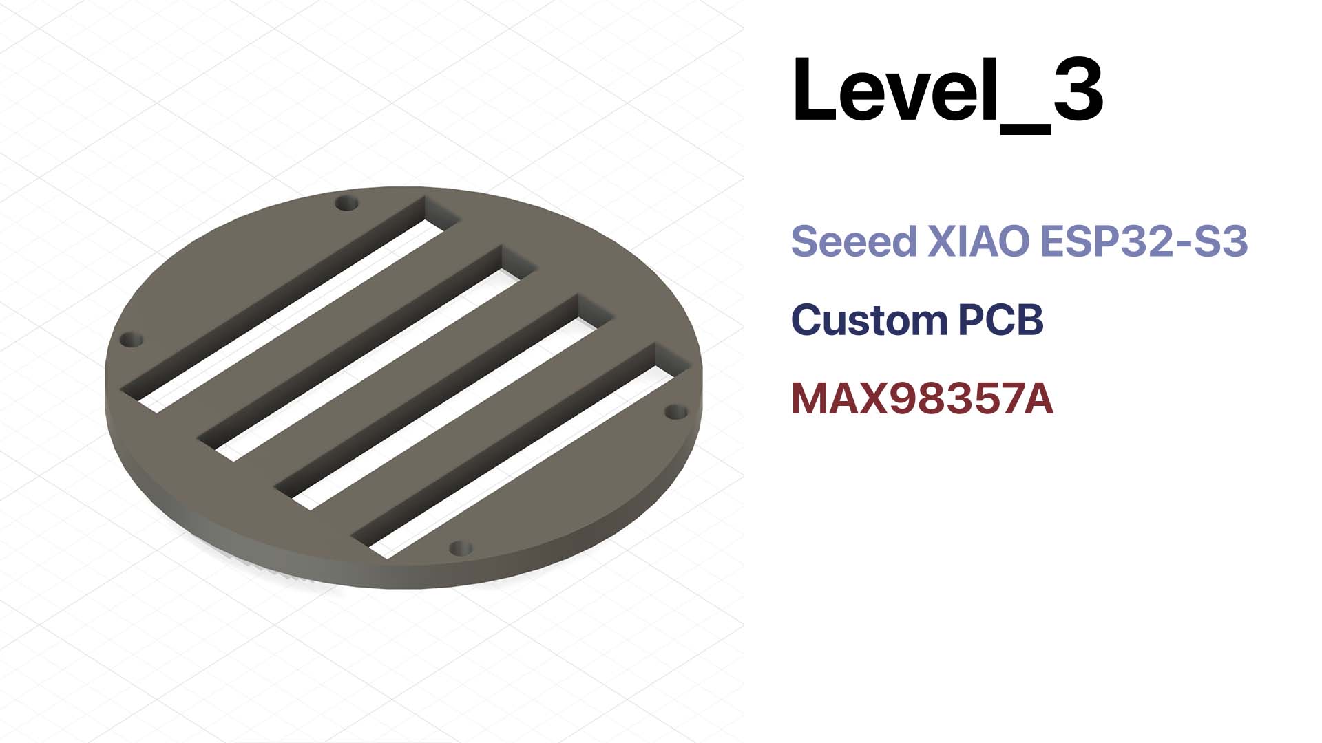
After I defined the component placement, I developed the final structure for Level 3. This layer works as the control center of the robot. It also provides the mounting surface for the main electronics.
Assembly Logic
I assembled the internal system as a layered stack from bottom to top. This packaging strategy organizes the internal space. It also makes the system easier to assemble, understand, and repair.
- I prepare the lower structure and mount the four servos in Level 1.
- I install the speaker, ToF sensor, and WS2812B light on the lower layer.
- I place the battery and PCA9685 servo driver in Level 2.
- I install the Seeed XIAO ESP32-S3, custom PCB, and MAX98357A on Level 3.
- I route the wires between the three levels and keep them away from moving parts.
- I close the stacked structure inside the outer shell and test the complete robot.
This layered assembly method also helps with repair. It does not treat the inside as one crowded space. Instead, it separates motion, power, and control into clearer zones.
Integrated Test Evidence
After I planned the packaging, I tested the integrated robot as one system. These tests were important. A module can work on the bench but fail after I enclose it inside the body.
LED feedback test
Movement test — open assembly
Movement test — with shell installed
AI interaction test
Failure Modes
I also considered what might go wrong after integration. This helped me think beyond a working prototype. Loco Pik also needs to survive assembly, repeated testing, and repair.
| Failure area | Possible problem | My consideration |
|---|---|---|
| Mechanical | Legs bind against the shell, servo horn loosens, or the shell cracks. | I leave enough clearance, center the servos before assembly, and avoid thin stress points. |
| Wiring | Wires are pulled, scratched, or pinched during assembly or movement. | I separate wiring from moving areas and keep enough slack for repair. |
| Power | Voltage drops reset the ESP32 when servos or LEDs draw high current. | I keep a clear power path, use common ground, and plan for current spikes. |
| Software | Commands overlap or the robot stays stuck in one state. | I use simple state recovery and test each combined behavior after packaging. |
Repair and Lifecycle
Loco Pik should not become a sealed object after assembly. I still need to adjust it because it is a prototype. I need to reopen the body, check the connectors, replace a servo, or update the control board.
The layered structure supports this repair approach. It separates motion, power, and control into clearer zones. This makes the robot easier to understand and maintain. It also improves the reuse value of standard parts, such as the servos, battery, ESP32-S3, and amplifier.
Link to Final Project
I also need to add a direct link from my final project page to this Week 15 documentation page. This link will complete the checklist.
Suggested final project link:
<a href="./assignments/week15.html">Week 15 — System Integration</a>
AI Use Statement
I used ChatGPT to help organize and rewrite the English text for this Week 15 page. ChatGPT helped me structure the documentation around the Fab Academy checklist. It also helped me connect the writing to my CAD, assembly, and testing evidence.
The project idea, design decisions, packaging logic, CAD development, and tests are my own work. I reviewed the AI-assisted writing before publishing it. I also edited the text to match my own process.