


Intelligence.
Voice becomes behavior.
Loco Pik can connect to an ESP32-based AI dialogue system, turning voice interaction into sound, light, and tiny movements.
Watch the video
Final Project Summary
Final Project Documentation
I moved from sketches to fabrication, electronics, programming, integration, and testing.
Image source note:Image source note: images below this line include AI-assisted concept visualizations; images above this line are documentation materials from the actual project process, including design screenshots, fabrication photos, electronics tests, system integration records, and final prototype documentation.
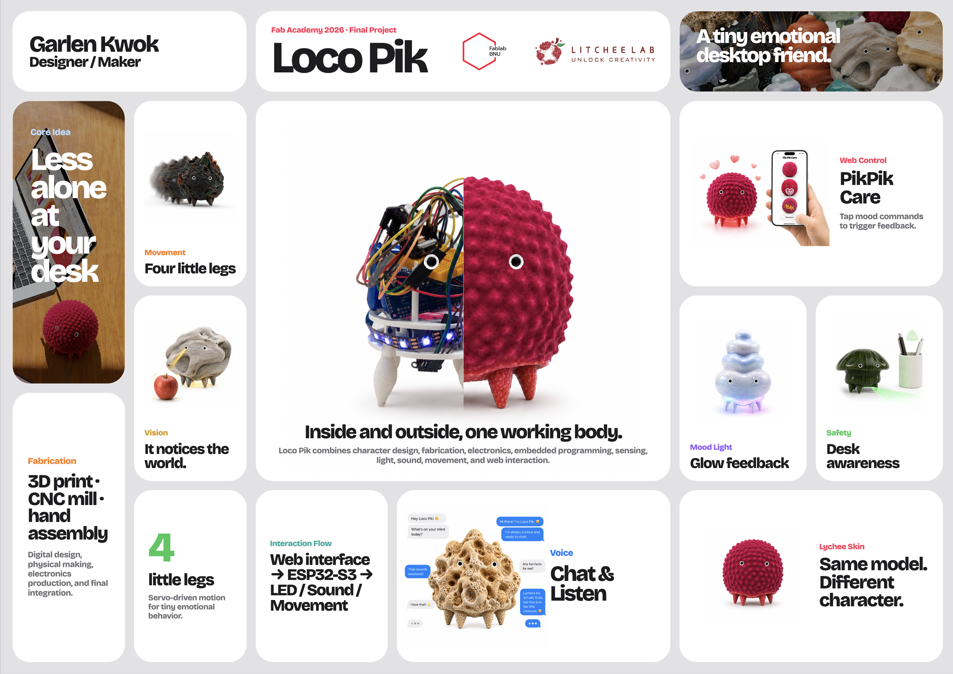
A tiny desktop creature that can talk, walk, see, glow, and stay safe on your desk.
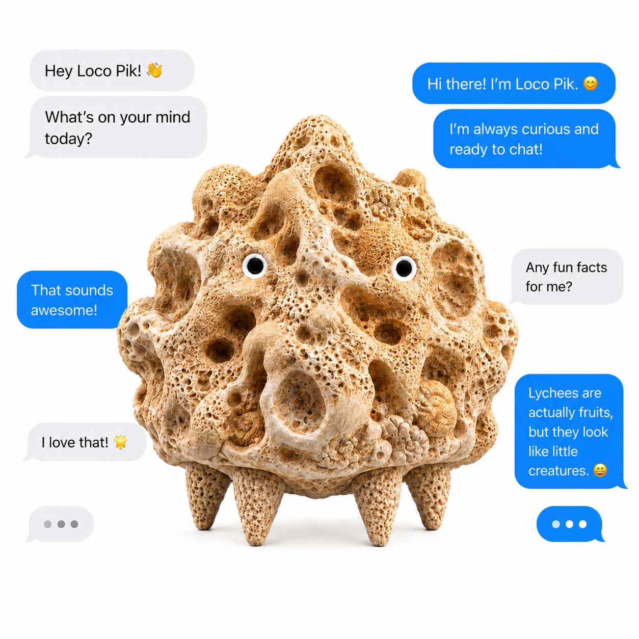
Loco Pik is a tiny alien-like companion that quietly lands on your desk. It reacts with small movements, gentle lights, curious sounds, and a simple face that feels alive.
Design
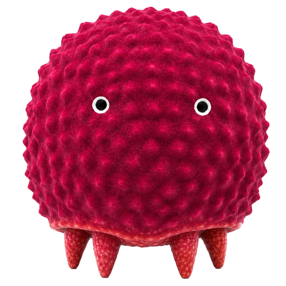
Loco Pik has a small rounded shell, two tiny sensing holes, and four little legs. It looks simple and quiet, like a small creature seeing the world for the first time.
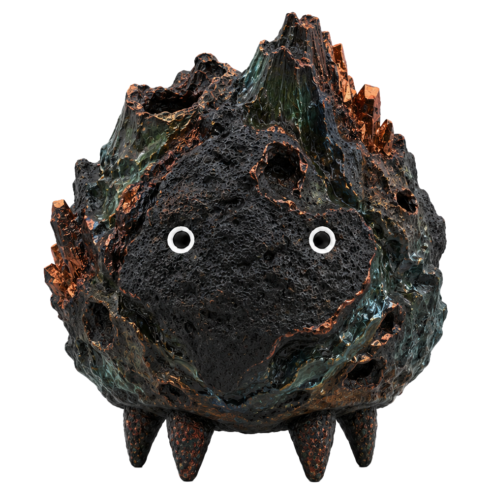
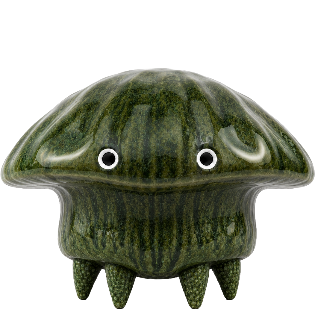
Each shell material gives Loco Pik a different personality. Lychee feels sweet and playful. Stone feels calm and steady. Crystal feels clear and curious.
Same little heart. Different little souls.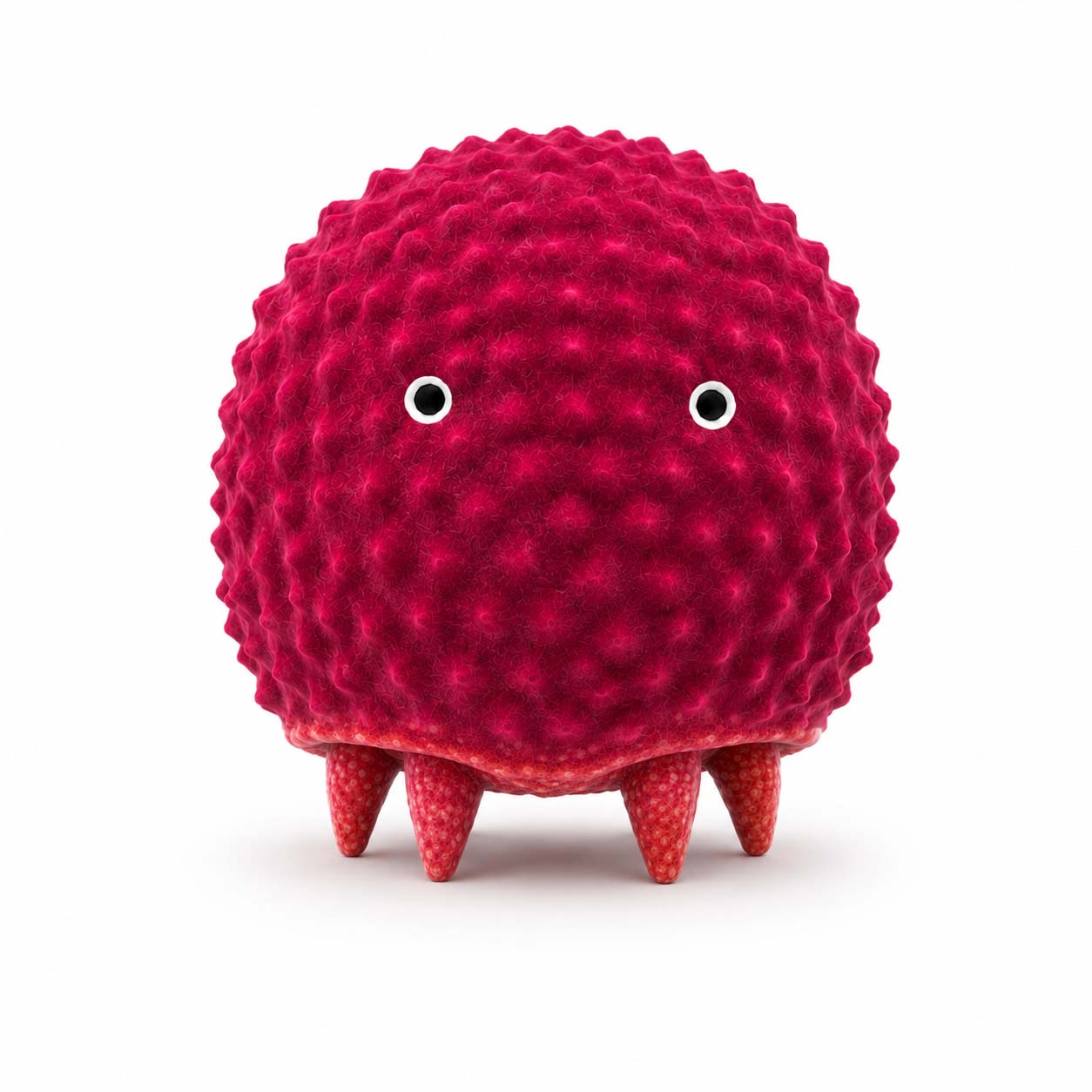
A bright and playful Loco Pik with a lychee-like shell. It feels sweet, lively, and easily excited.
Interaction System
Loco Pik brings together AI voice, movement, vision, mood lighting, web control, and distance sensing, so this small desktop creature can respond in many little ways.
Intelligence.
Loco Pik can connect to an ESP32-based AI dialogue system, turning voice interaction into sound, light, and tiny movements.

Movement.
Four servo-driven legs let it take small steps, turn curiously, move backward nervously, and idle sleepily.

Vision.
The onboard camera helps Loco Pik notice simple objects and visual events in front of it.
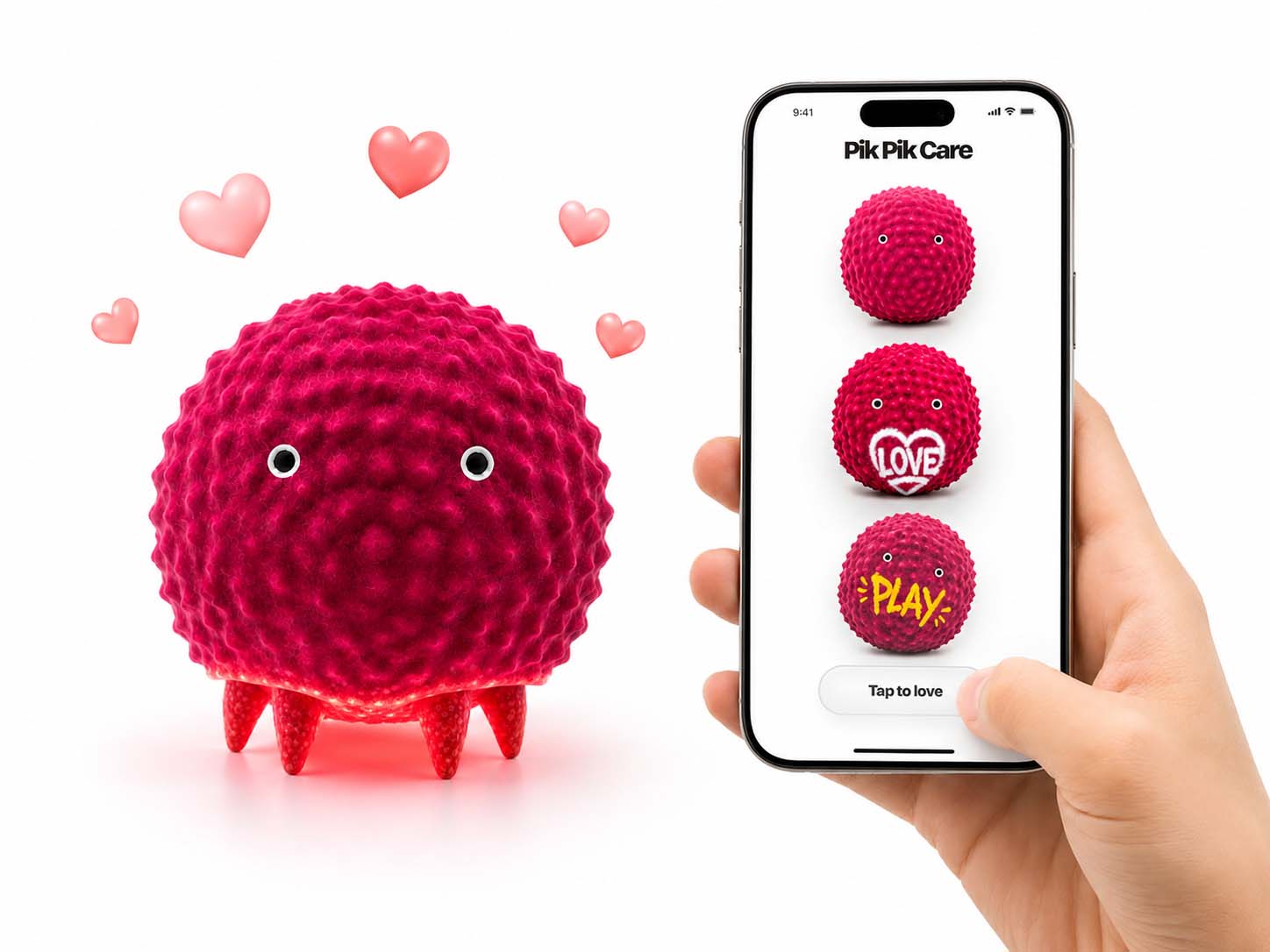
LocoPik Lab.
The web interface turns taps into moods, lights, movements, sound feedback, and interaction modes.

Mood.
A hidden RGB light strip lets emotional states appear through color instead of a screen.
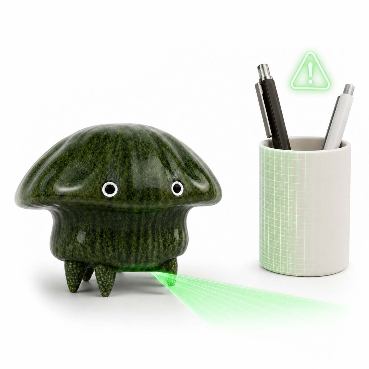
Safety.
A ToF distance sensor helps it detect obstacles and avoid moving too close to the edge of the desk.
I would like to thank Harvey for writing and sharing the Xiaozhi AI code, which gave Loco Pik the possibility of voice conversation and AI companionship.
I would also like to thank Lee and Lynch for their support and advice during the development of this project, and LitLiao and Litchee Lab for providing the lab environment, technical support, and making community that helped this project move forward.
Special thanks to Wang Yubin and FabLab Beijing Normal University for their help, support, and encouragement throughout the process.