Overview
For Week 12, I explored mechanical design through a kinetic mechanical clock prototype. The project was inspired by kinetic mechanical sculptures, especially circular mechanisms that create movement through repeated linkage parts.
The final prototype combines several fabrication methods. The main moving linkage parts were made from 3 mm laser-cut wood board. The motor holder and fixing parts were designed in Fusion 360 and made with 3D printing. The clock structure was supported by aluminum extrusion, and a stepper motor was used as the actuator.
The purpose of this project was not only to make a clock, but also to make time visible as a mechanical movement. The clock face changes its form through the linkage mechanism, turning time into a kinetic visual experience.
Assignment
Group Assignment
The group assignment was to design a machine that includes mechanism, actuation, automation, function, and user interface. We also needed to build the mechanical parts, operate them manually, and document the group project and individual contribution.
Individual Assignment
My individual work focused on the mechanical part of the kinetic clock. I studied the reference mechanism, designed the parts, made the laser-cut pieces, assembled the aluminum frame, and tested the linkage movement. The stepper motor control code was supported by my group members.
Project Concept: Kinetic Mechanical Sculpture Style
At the beginning of this project, I wanted to make a clock with a strong mechanical and sculptural feeling. I looked at kinetic mechanical sculpture references and found that repeated radial parts can create a rich motion effect when they are driven by a single rotating center.
I defined the project as a kinetic mechanical clock prototype. The clock uses repeated linkage parts around the center shaft. When the center part rotates, the surrounding parts move together and create an opening and closing movement.


This project was also inspired by the kinetic clock works from Animaro Design . I used this reference to understand how a linkage mechanism can be used to visualize time, then made my own prototype with the fabrication methods available in the Fab Lab.
System Design
The system can be divided into four main parts: the linkage clock mechanism, the support structure, the actuator, and the control system. The clock face is driven from the center. The stepper motor rotates the center shaft, and the surrounding linkage parts transform this rotation into a changing circular form.
Final System Logic
Stepper motor rotates
        ↓
Center shaft turns
        ↓
Center hand drives the linkage mechanism
        ↓
Repeated wooden linkage parts move together
        ↓
Clock face opens and closes
        ↓
Mechanical movement visualizes the passing of time| Part | Function |
|---|---|
| Laser-cut wooden linkage parts | Create the repeated moving clock face |
| Motor holder and center hand | Fix the stepper motor and transfer rotation to the mechanism |
| Aluminum extrusion | Support the clock mechanism and make the frame adjustable |
| 42BYGH stepper motor | Drive the center shaft |
| TMC2209 driver | Control the stepper motor |
| XIAO ESP32S3 | Send DIR, STEP, and ENABLE signals to the motor driver |
Step 1: Reference and Mechanism Study
First, I studied the working principle of a kinetic linkage clock. The most important idea is that one central rotating part can control many repeated linkage modules around the clock face. When the center part rotates, the whole linkage system changes between a closed shape and an open circular shape.
I analyzed the visual style and the movement logic. I wanted the final object to look like a mechanical sculpture, so I kept the repeated radial pattern and visible mechanical joints.
At this stage, I mainly used the reference images and my own manual tests to understand the mechanism. I did not make a separate motion analysis drawing, so I focused the documentation on the physical prototype tests instead.
Step 2: 3D Printed Linkage Test
Before making the wooden version, I first tested the linkage mechanism with 3D printed parts. This stage helped me understand the basic movement, the joint positions, and how the repeated parts form a circular clock face.
This first test was mainly a manual mechanical test. I did not use a motor at this stage. I moved the parts by hand to observe how the mechanism opened and closed.
During this test, I found that the 3D printed joints were relatively stiff. Because the holes and printed surfaces had friction, the movement required more force than expected. This showed me that the final version needed better joint clearance and smoother material behavior.
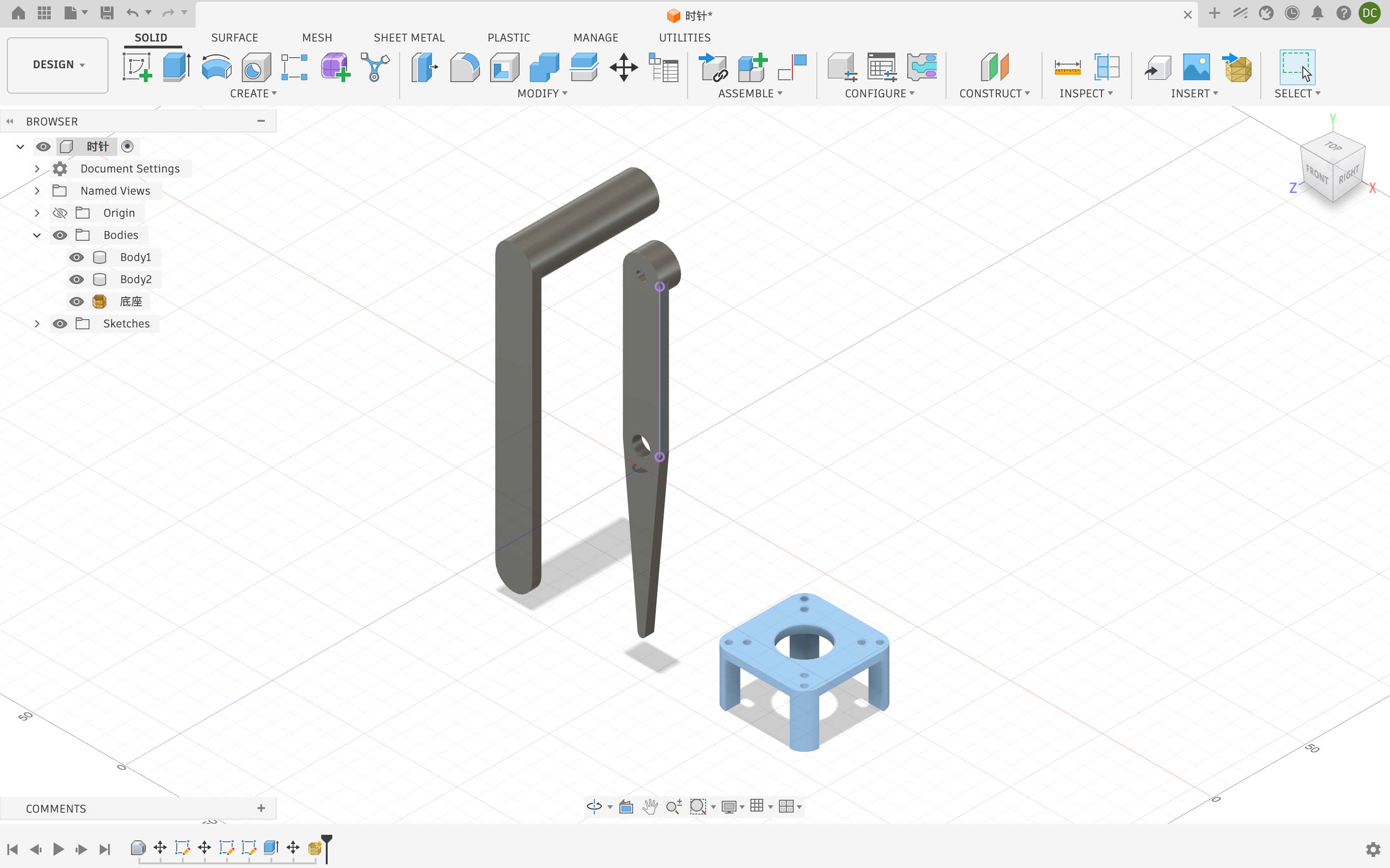
Step 3: CAD Design and Fabrication Planning
After the first test, I continued to model and adjust the parts in Fusion 360. I separated the project into different mechanical parts: linkage parts, center hand, motor holder, and frame connection parts.
I decided to use laser cutting for the repeated linkage parts because they are flat, repeated, and need to be produced many times. Laser cutting is faster and more suitable for this type of part compared with printing every linkage piece.
Main Design Decisions
- The linkage parts were designed as flat 2D parts.
- The main material for the linkage parts was 3 mm wood board.
- The motor holder and center hand were designed in Fusion 360.
- The frame used aluminum extrusion for better rigidity.
- M3 screws and nuts were used as pivot joints.
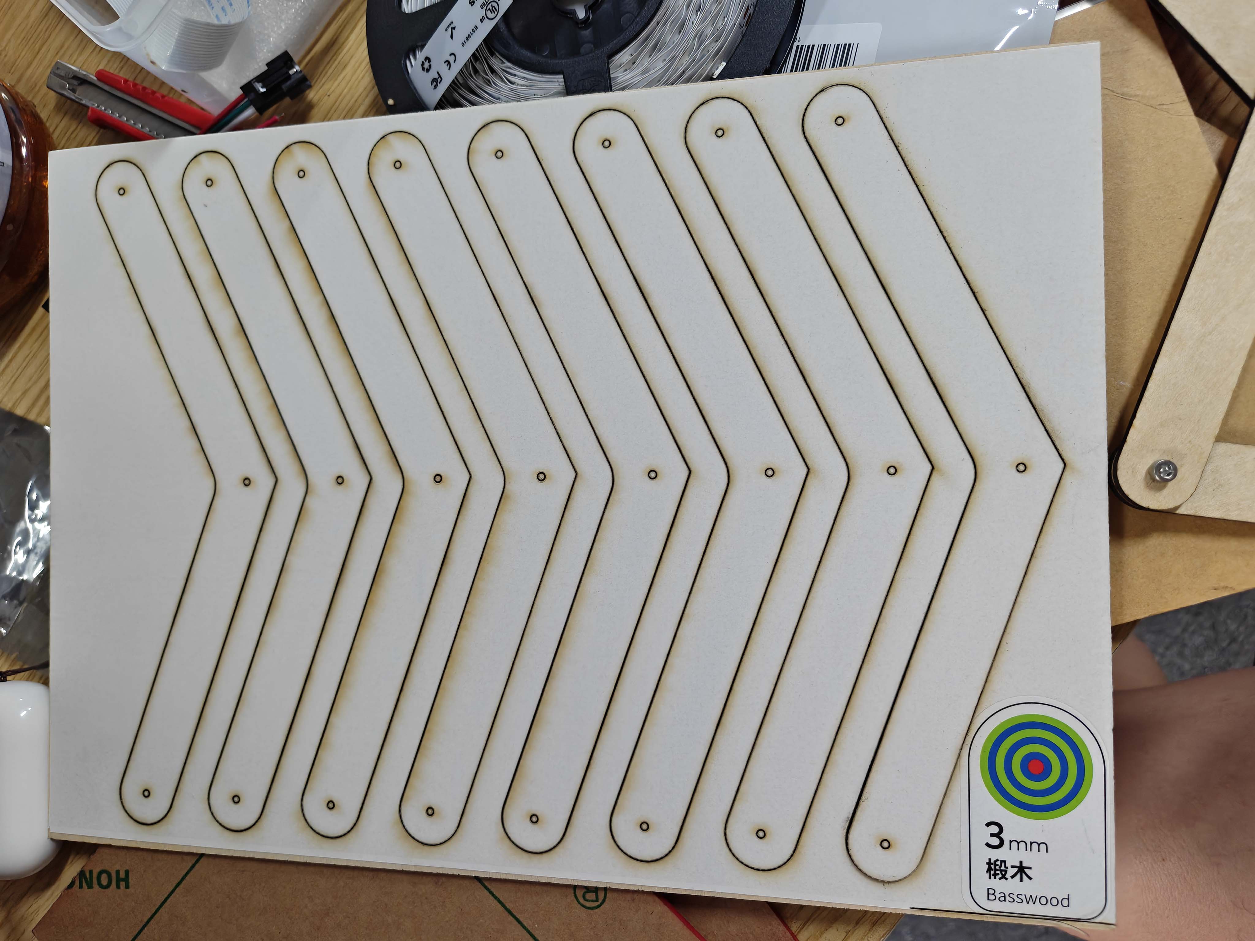
Step 4: Laser Cutting the Wooden Linkage Parts
After the 3D printed test, I changed the main linkage parts to 3 mm laser-cut wood board. The wooden parts were lighter and faster to fabricate, which made them more suitable for a clock face with many repeated linkage components.
The holes on the parts were designed for M3 screws, so each part could rotate around its joint point. The laser-cut parts helped reduce weight, but the mechanism still needed careful adjustment because it contained many pivot joints.
Step 5: Designing the Motor Holder and Center Hand
The actuator of the clock was a 42BYGH series stepper motor. This motor is similar to a NEMA 17 stepper motor. It has a square front face, four M3 mounting holes, and a 5 mm output shaft. I used these dimensions as the basis for designing the motor fixing structure.
I used the motor dimension drawing to design the motor holder and the center hand in Fusion 360. The motor holder was used to position and fix the stepper motor, while the center hand was designed to transfer the motor rotation to the linkage clock mechanism.
Since the clock face was driven from the center, the relationship between the motor shaft, the center hand, and the linkage parts was very important. If the center hand was not aligned with the motor shaft, the linkage structure would create extra friction during movement.
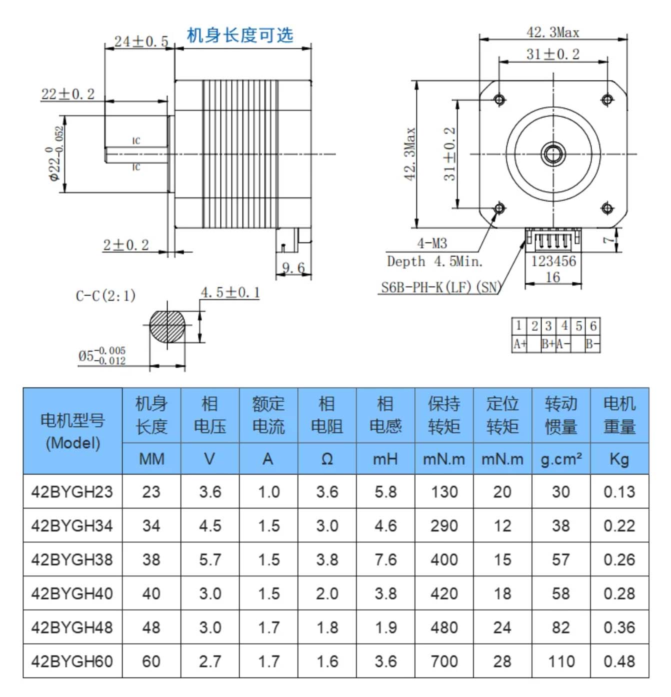
Motor Holder Design Parameters
| Feature | Dimension | Reason |
|---|---|---|
| Motor pocket | 43.2 mm × 43.2 mm |
The motor body is about 42.3 mm, so I added clearance for 3D printing and assembly tolerance. |
| Mounting hole distance | 31 mm × 31 mm |
This matches the motor dimension drawing and the M3 mounting hole positions. |
| M3 mounting holes | 3.2 mm |
The holes are slightly larger than 3 mm to make assembly easier after fabrication. |
| Center opening | 23 mm |
This gives clearance for the front circular boss of the stepper motor. |
| Motor shaft | 5 mm |
The center hand needed to match the motor shaft position so that the rotation could be transferred to the linkage mechanism. |
Step 6: Frame and Support Structure
The clock needed a stable support structure because the linkage face was relatively large. I used aluminum extrusion to build the support frame. The vertical extrusion supports the clock face, and the base keeps the structure standing.
I did not record a separate frame assembly image, but the aluminum extrusion frame can be seen in the final prototype. It made the prototype easier to adjust during both the mechanical test and the motor test.
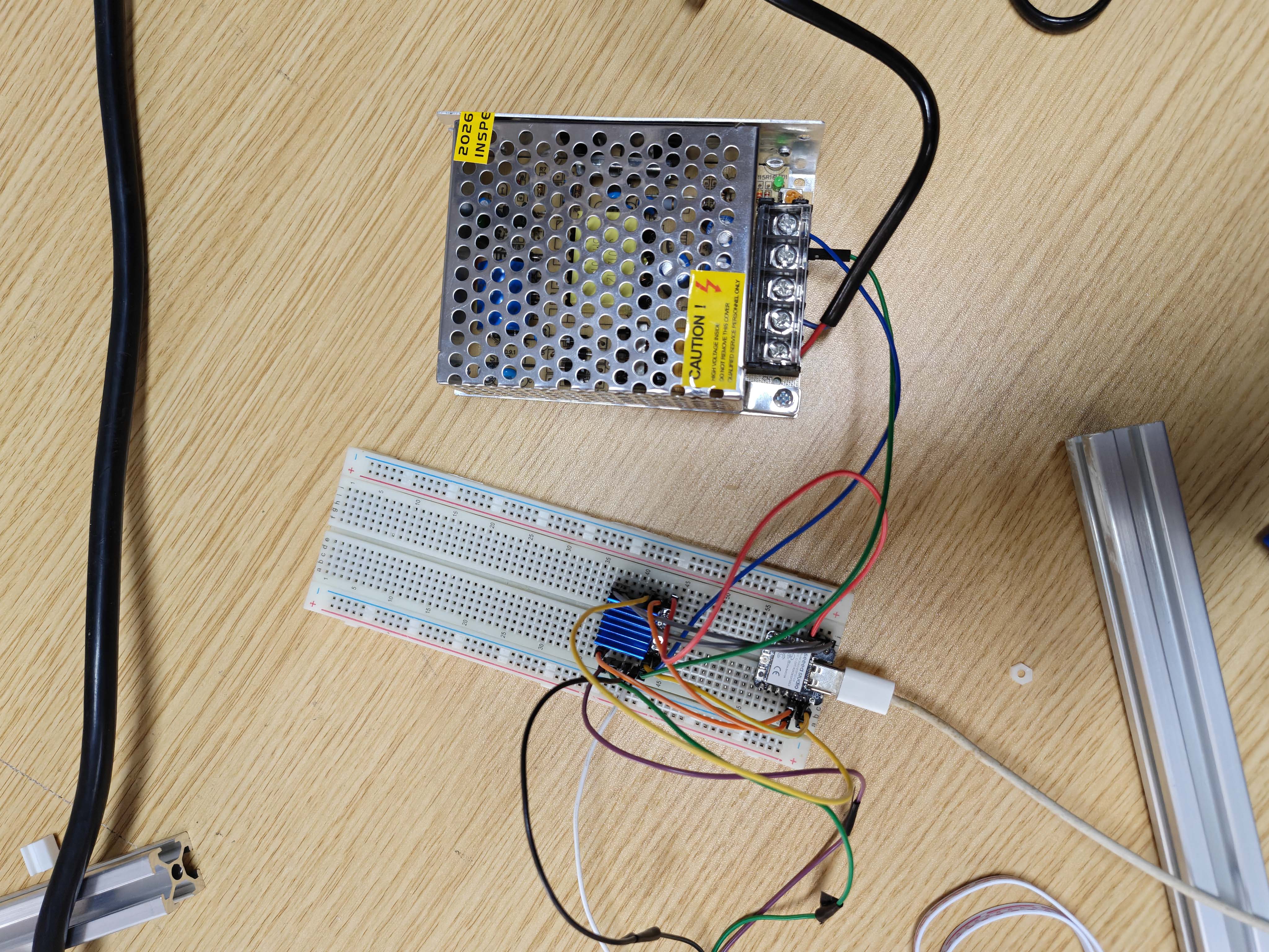
Step 7: Electronics and Wiring
I used a XIAO ESP32S3 to control a TMC2209 stepper motor driver. The TMC2209 receives DIR, STEP, and ENABLE signals from the microcontroller and drives the stepper motor with an external 12V power supply.
The motor power and the logic power are separated. The 12V power supply is connected to the motor power input of the TMC2209, while the XIAO provides logic control signals. The ground of the XIAO and the ground of the TMC2209 must be connected together.
Wiring Table
| Part | Connection |
|---|---|
| 12V power + | TMC2209 VM / VMOT / MOTOR V+ |
| 12V power - | TMC2209 GND |
| XIAO GND | TMC2209 GND |
| XIAO D0 | TMC2209 DIR |
| XIAO D1 | TMC2209 STEP |
| XIAO D2 | TMC2209 EN / ENABLE |
| Stepper motor coil A | TMC2209 A1 and A2 |
| Stepper motor coil B | TMC2209 B1 and B2 |
Step 8: Stepper Motor Control
After finishing the basic wiring, I tested the stepper motor control system with the XIAO ESP32S3 and the TMC2209 driver. Before connecting the motor to the full clock mechanism, I first needed to confirm that the motor could rotate correctly in both directions.
In the physical motor test video, I only tested the basic clockwise and counterclockwise rotation. This helped me check the wiring, the DIR pin, the STEP pin, the ENABLE pin, and the motor coil connection before using the motor to drive the clock structure.
User Interface
For this prototype, I used the Serial Monitor as a simple user interface. During the motor test, I could upload the program and observe the current tick count and motor position from the serial output. This helped me check whether the motor movement was working as expected.
In this version, the interface was mainly used for testing and debugging. In the next version, I want to replace it with a more physical interface, such as a button or a web-based control page, so the user can start, stop, or change the movement mode more easily.
After the direction test worked, my group members helped write a smoother clock demo program. This code was designed as a 60-second demo mode. The motor moves once every second and completes one full revolution in 60 seconds, similar to a second-hand movement. I used this code to test whether the mechanism could be driven more smoothly.
I used 60 ticks for one revolution. The motor moves to a
new target position every second. To make each movement smoother, I
used an ease-in-out function based on a cosine curve. This makes each
tick start slowly, accelerate in the middle, and slow down again before
stopping.
Control Logic of the 60-Second Demo Mode
60 ticks per revolution
        ↓
1 tick every second
        ↓
Stepper motor moves to the next target position
        ↓
Ease-in-out function smooths the movement
        ↓
The clock completes one full revolution in 60 seconds| Parameter | Value | Meaning |
|---|---|---|
TICKS_PER_REV |
60 |
The mechanism is divided into 60 positions for one full revolution. |
TICK_INTERVAL_MS |
1000 |
The motor moves once every second. |
MOVE_TIME_MS |
350 |
Each tick movement takes 350 ms, making the motion smoother. |
FULL_STEPS_PER_REV |
200 |
The stepper motor has 200 full steps per revolution. |
MICROSTEPS |
8 |
The TMC2209 was used with 8 microsteps. |
STEPS_PER_REV |
1600 |
200 full steps multiplied by 8 microsteps. |
60-Second Demo Mode Code with Group Support
#ifndef D0
#define D0 2
#endif
#ifndef D1
#define D1 3
#endif
#ifndef D2
#define D2 4
#endif

#include <math.h>

const uint8_t PIN_DIR = D0;
const uint8_t PIN_STEP = D1;
const uint8_t PIN_ENABLE = D2;

const bool ENABLE_ACTIVE_LOW = true;
const bool DIR_INVERT = true;

const int FULL_STEPS_PER_REV = 200;
const int MICROSTEPS = 8;
const long STEPS_PER_REV = (long)FULL_STEPS_PER_REV * MICROSTEPS;

// Clock movement parameters
const int TICKS_PER_REV = 60;        // second-hand effect: 60 ticks per revolution
const int MOVE_TIME_MS = 350;        // movement duration for each tick
const int TICK_INTERVAL_MS = 1000;   // move once every second

const uint16_t STEP_PULSE_US = 4;

long currentPosition = 0;
long tickCount = 0;
unsigned long nextTickTime = 0;

void setEnable(bool enable) {
  if (ENABLE_ACTIVE_LOW) {
    digitalWrite(PIN_ENABLE, enable ? LOW : HIGH);
  } else {
    digitalWrite(PIN_ENABLE, enable ? HIGH : LOW);
  }
}

void setDirection(int direction) {
  bool level = direction > 0;
  if (DIR_INVERT) level = !level;
  digitalWrite(PIN_DIR, level ? HIGH : LOW);
}

void doStep() {
  digitalWrite(PIN_STEP, HIGH);
  delayMicroseconds(STEP_PULSE_US);
  digitalWrite(PIN_STEP, LOW);
  delayMicroseconds(STEP_PULSE_US);
}

// Ease-in-out movement function
float easeInOut(float t) {
  return 0.5f - 0.5f * cosf(PI * t);
}

// Smoothly move to a target step position
void smoothMoveTo(long targetPosition, int durationMs) {
  long startPosition = currentPosition;
  long distance = targetPosition - startPosition;

  if (distance == 0) return;

  int direction = distance > 0 ? 1 : -1;
  setDirection(direction);

  unsigned long startTime = millis();

  while (true) {
    unsigned long now = millis();
    float t = (float)(now - startTime) / durationMs;

    if (t >= 1.0f) break;

    float eased = easeInOut(t);
    long desiredPosition = startPosition + round(distance * eased);

    while (currentPosition != desiredPosition) {
      doStep();
      currentPosition += direction;
    }
  }

  // Final correction to make sure every tick position is accurate
  while (currentPosition != targetPosition) {
    doStep();
    currentPosition += direction;
  }
}

void setup() {
  pinMode(PIN_DIR, OUTPUT);
  pinMode(PIN_STEP, OUTPUT);
  pinMode(PIN_ENABLE, OUTPUT);

  digitalWrite(PIN_STEP, LOW);
  setEnable(true);

  Serial.begin(115200);
  delay(300);

  Serial.println("Smooth clock stepper started.");
  Serial.println("1 tick per second.");

  nextTickTime = millis() + TICK_INTERVAL_MS;
}

void loop() {
  if (millis() >= nextTickTime) {
    tickCount++;

    // Use accumulated target position to avoid rounding error from 1600 / 60
    long targetPosition = round((float)tickCount * STEPS_PER_REV / TICKS_PER_REV);

    smoothMoveTo(targetPosition, MOVE_TIME_MS);

    Serial.print("Tick: ");
    Serial.print(tickCount);
    Serial.print("  Position: ");
    Serial.println(currentPosition);

    nextTickTime += TICK_INTERVAL_MS;
  }
}
In this code, the motor uses an accumulated target position instead of
moving a fixed number of steps every time. This is important because
1600 / 60 is not an integer. If the code moved the same
rounded step value every second, the error would accumulate over time.
By calculating the target position from the total tick count, the final
position stays more accurate.
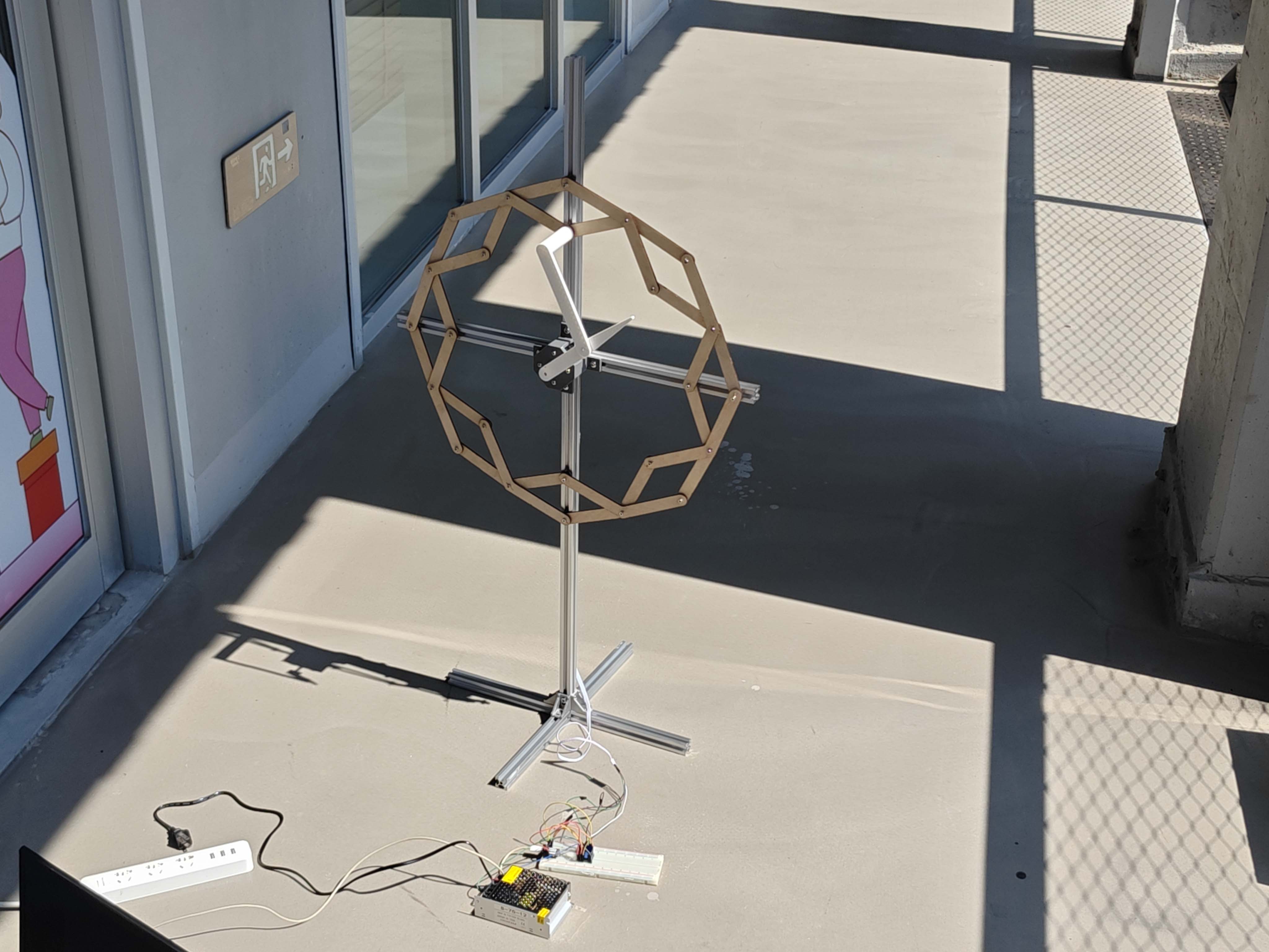
Step 9: Final Assembly
After testing the linkage parts, the motor holder, and the electronics separately, I assembled the final prototype. The laser-cut wooden clock face was mounted to the support structure. The stepper motor was fixed behind the center using the motor holder.
The electronics were connected on a breadboard during this stage. The 12V power supply powered the motor driver, and the XIAO ESP32S3 sent control signals to the TMC2209.
Materials and Components
| Material / Component | Use |
|---|---|
| 3 mm wood board | Laser-cut linkage parts for the clock face |
| PLA filament | 3D printed fixing parts and early linkage tests |
| Aluminum extrusion | Main frame and support structure |
| 42BYGH stepper motor | Actuator for rotating the center shaft |
| TMC2209 stepper motor driver | Driver for controlling the stepper motor |
| XIAO ESP32S3 | Microcontroller for DIR, STEP, and ENABLE control signals |
| 12V power supply | External motor power supply |
| M3 screws and nuts | Pivot joints and assembly fasteners |
| Breadboard and jumper wires | Temporary circuit connection for testing |
Problems and Solutions
| Problem | Reason | Solution |
|---|---|---|
| The 3D printed linkage movement was stiff. | The printed joints and hole surfaces had friction, so the mechanism required more force to move. | I used the test to understand the movement and changed the main linkage parts to laser-cut wood for the next version. |
| The wooden linkage still needed careful adjustment. | The clock face had many pivot joints, and each joint affected the total friction of the mechanism. | I adjusted the tightness of the screws and tested the motion manually before connecting the motor. |
| The motor holder needed tolerance adjustment. | The motor size was close to the designed pocket size. | I added clearance around the motor body and used slightly larger M3 holes. |
| The motor shaft and center hand needed better alignment. | If the shaft was not aligned, the linkage structure produced extra friction. | I adjusted the motor holder position and tested the rotation manually before powering the motor. |
| The wiring was still temporary. | The test circuit was built on a breadboard. | In the next version, I should make a cleaner control board and fix the wires to the frame. |
What I Learned
This week helped me understand that mechanical design is not only about drawing shapes in CAD. The position of every hole, the clearance between moving parts, and the alignment of the motor shaft all affect whether the machine can move smoothly.
I also learned that a linkage mechanism should be tested manually before adding motor control. Manual testing helped me find friction, looseness, and alignment problems before the electronics were added.
Another important lesson was material selection. 3D printing was useful for customized fixing parts and early tests, while laser cutting was more efficient for producing many repeated flat linkage parts. Aluminum extrusion was useful for building a stable and adjustable support structure.
Reflection
This project connected mechanical design, digital fabrication, electronics, and programming. The result is a kinetic mechanical clock prototype that uses a physical mechanism to visualize time.
The clock is not only a time display, but also a mechanical visualization of time. The repeated linkage parts create a sculptural movement, and the stepper motor makes the movement controllable.
For the next version, I want to improve the center shaft structure, reduce friction between the linkage parts, make the wiring cleaner, and add a better user interface such as buttons or a web control page.
Work Division and Collaboration
This prototype was not completed completely alone. My main work was the mechanical design, fabrication, assembly, and documentation. My group members mainly helped with the stepper motor control code.
The percentage below is a rough estimate. It shows how the work was divided in this prototype.
| Task | Main person | Approx. contribution |
|---|---|---|
| Concept and mechanism direction | Garlen | 100% |
| Reference study and mechanism testing | Garlen | 100% |
| CAD design for mechanical parts | Garlen | 100% |
| Laser cutting and wooden linkage parts | Garlen | 100% |
| Aluminum extrusion frame | Garlen | 100% |
| Part assembly and mechanical adjustment | Garlen | 100% |
| Stepper motor control code | Group members | About 80% group members / 20% Garlen testing |
| Final documentation | Garlen | 100% |
Overall, I completed about 75% of this prototype work. This included the design, laser cutting, aluminum structure, assembly, mechanical testing, and documentation. My group members supported about 25% of the work, mainly on the code writing and motor control logic.
My Individual Contribution
My main contribution was the mechanical design and fabrication of the kinetic clock prototype. I researched the kinetic mechanical sculpture style, analyzed the linkage clock reference, tested the 3D printed linkage mechanism, prepared the laser-cut wooden linkage parts, designed the motor holder and center hand in Fusion 360, assembled the aluminum extrusion structure, adjusted the mechanism, and documented the process.
For the programming part, my group members helped write the stepper motor control code. I used the code for testing and checked how the motor movement worked with my mechanical structure.