Overview
This week was about communication between different nodes. In previous weeks, most of my input and output tests happened on one board. This time, I separated the system into two microcontroller nodes and used MQTT to connect them wirelessly.
The XIAO ESP32S3 Sense was used as the input node. It used the camera
and a local fruit recognition model to detect whether there was an
apple in front of it. When the model detected an apple, the S3
published the message apple through MQTT.
The XIAO ESP32-C3 was used as the output node. It subscribed to the
same MQTT topic. When the C3 received the message
apple, it turned on the Grove RGB LED for five seconds.
Assignment
Group Assignment
The group assignment was to send a message between two projects. I tested MQTT communication with MQTT Explorer and used it to send messages to the XIAO ESP32-C3 receiver node.
Individual Assignment
The individual assignment was to design, build, and connect wired or wireless node(s) with network or bus addresses and local input and/or output device(s). I built a wireless two-node system: the S3 worked as the input node, and the C3 worked as the output node.
System Design
I used MQTT as the communication method. MQTT uses a publish and subscribe structure. The sender publishes a message to a topic, and the receiver subscribes to that topic. The two boards do not need to be directly connected by wires.
Final System Logic
XIAO ESP32S3 Sense camera sees an apple
        ↓
Local fruit recognition model detects apple
        ↓
S3 publishes MQTT message: apple
        ↓
MQTT broker receives the message
        ↓
XIAO ESP32-C3 subscribes to the same topic
        ↓
C3 receives apple
        ↓
Grove RGB LED turns red for five seconds| Item | Value |
|---|---|
| MQTT broker | broker.hivemq.com |
| Port | 1883 |
| Topic | litchee/garlen/week11/apple |
| Message | apple |
Step 1: Installing MQTT Explorer
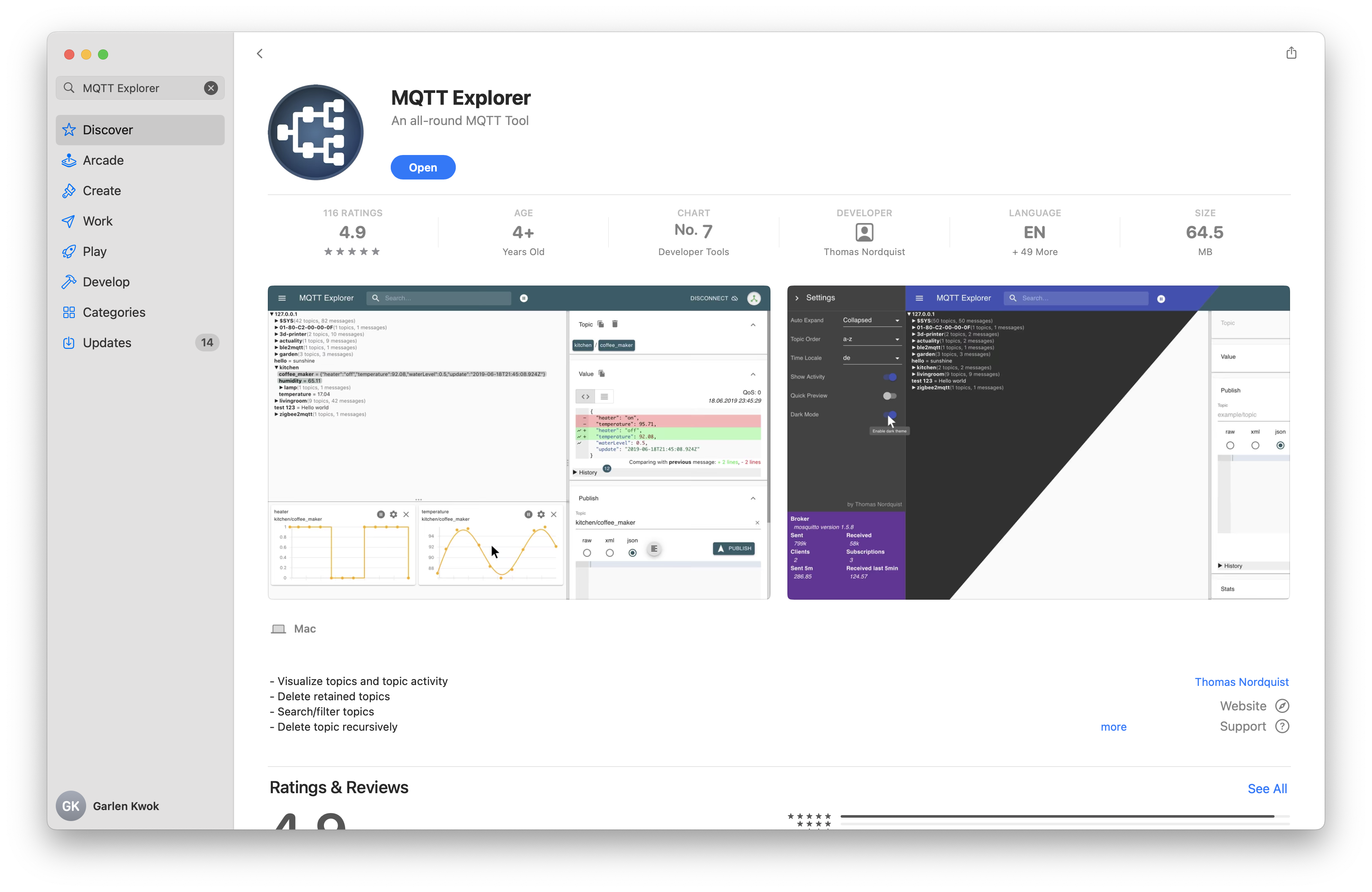
At the beginning, I needed a tool to observe and test MQTT messages before connecting the two boards together. I used MQTT Explorer because it can show MQTT topics clearly and can also manually publish test messages.
MQTT Explorer can be downloaded from its official website: https://mqtt-explorer.com/ . At first, I tried to download the app from the website, but macOS blocked the downloaded application. To avoid spending too much time on this installation problem, I downloaded MQTT Explorer directly from the App Store.
MQTT Explorer Download and Broker Setting
For the MQTT server, I used the HiveMQ public MQTT broker. The
broker address was broker.hivemq.com. HiveMQ provides
a public MQTT broker for testing MQTT clients and messages:
HiveMQ Public MQTT Broker
.
In the MQTT Explorer connection window, I filled in the following
information. I used the normal MQTT protocol without TLS encryption,
so the port was 1883. I did not need a username or
password for this public broker.
| Setting | Value | Explanation |
|---|---|---|
| Name | Week11 Apple MQTT |
This is only the local name of my connection in MQTT Explorer. |
| Protocol | mqtt:// |
I used the normal MQTT protocol. |
| Host | broker.hivemq.com |
This is the public MQTT broker server used in my test. |
| Port | 1883 |
Port 1883 is the standard MQTT port without TLS. |
| Username | Empty | No username was required for this public test broker. |
| Password | Empty | No password was required for this public test broker. |
| Validate certificate | Off | I did not use TLS, so certificate validation was not needed. |
| Encryption / TLS | Off | I used mqtt:// and port 1883. |
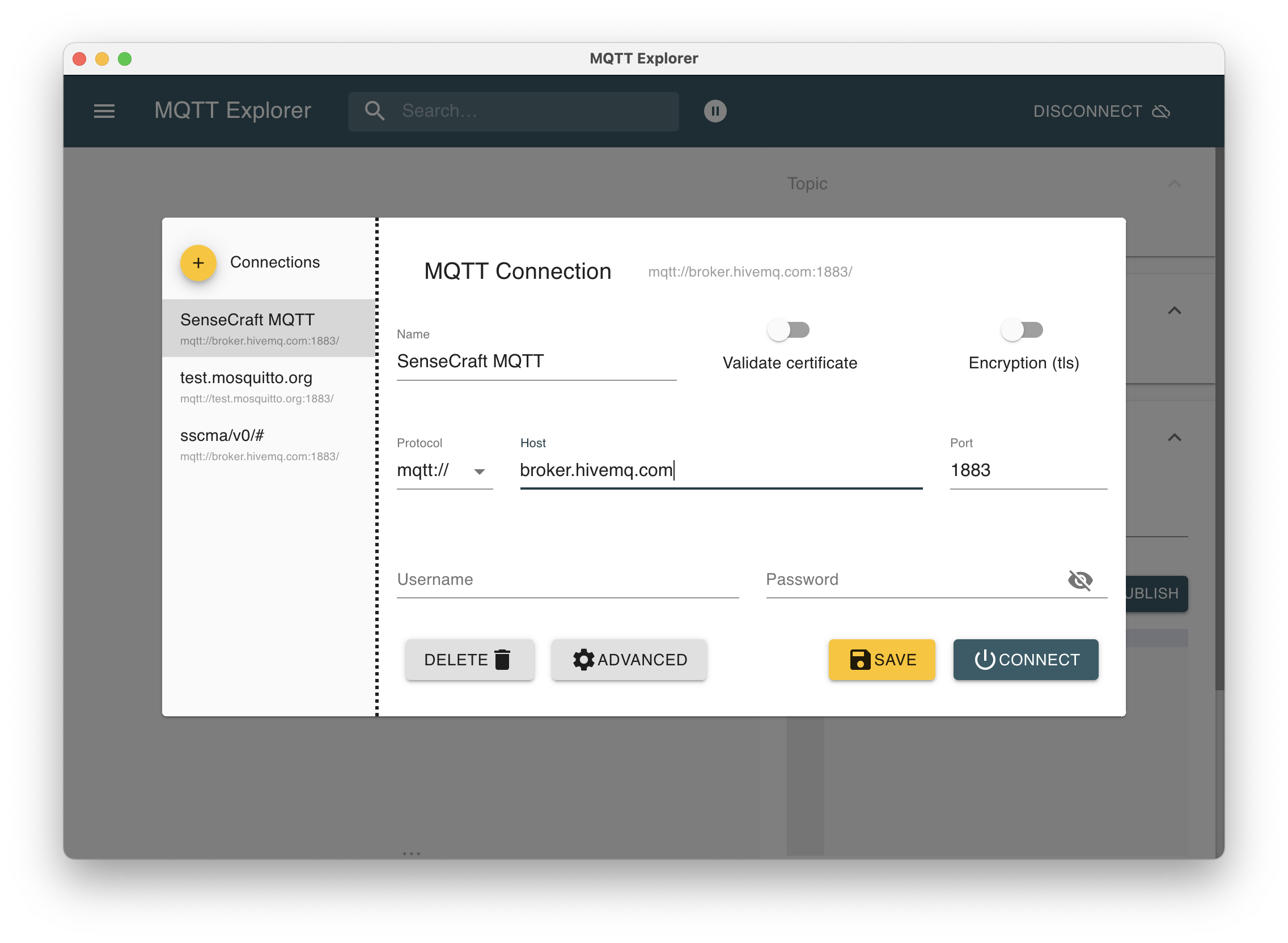
broker.hivemq.com as the host and
1883 as the MQTT port.
Step 2: Manual MQTT Test with the C3
Before adding the S3 camera node, I first tested whether the C3 could
receive MQTT messages and control the RGB LED. In MQTT Explorer, I
manually published two messages: apple and
no_apple.
In this early test, apple was used to turn on the RGB LED,
and no_apple was used to turn it off. This helped me
confirm that the C3, the MQTT topic, and the RGB LED wiring were
working correctly.
Manual Publish Setting in MQTT Explorer
After connecting to the broker, I used the Publish panel on the right side of MQTT Explorer to send test messages. This allowed me to test the C3 receiver before adding the S3 camera node.
| Publish setting | Value |
|---|---|
| Topic | litchee/garlen/week11/apple |
| Payload type | raw |
| Payload for LED on | apple |
| Payload for early LED off test | no_apple |
| QoS | 0 |
| Retain | Unchecked |
In the final version, I only kept the apple message.
The C3 turned on the RGB LED for five seconds after receiving
apple, and then the LED turned off automatically.
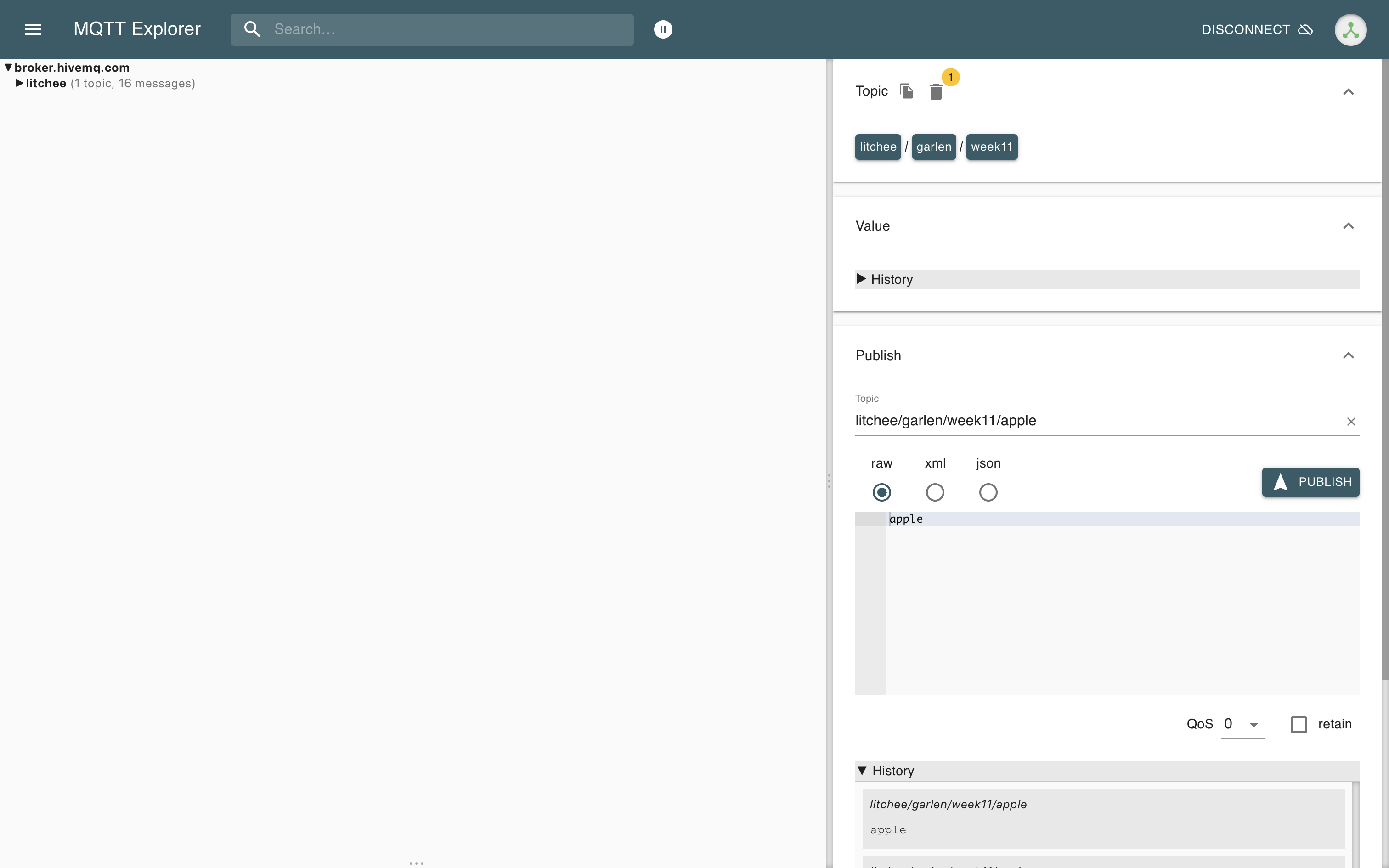
litchee/garlen/week11/apple and published the
payload apple.
apple and no_apple messages with
the C3 receiver and RGB LED.
Step 3: Building the C3 RGB LED Output Node
The output node was built with a XIAO ESP32-C3 and a Grove RGB LED module. The C3 subscribed to the MQTT topic and controlled the RGB LED according to the received message.
RGB LED Wiring
| Grove RGB LED | XIAO ESP32-C3 | Function |
|---|---|---|
| Red wire | 3V3 | Power |
| Black wire | GND | Ground |
| Yellow wire | D3 | Data |
| White wire | D2 | Clock |
Grove RGB LED red wire     → XIAO ESP32-C3 3V3
Grove RGB LED black wire   → XIAO ESP32-C3 GND
Grove RGB LED yellow wire  → XIAO ESP32-C3 D3
Grove RGB LED white wire   → XIAO ESP32-C3 D2
C3 Receiver Code
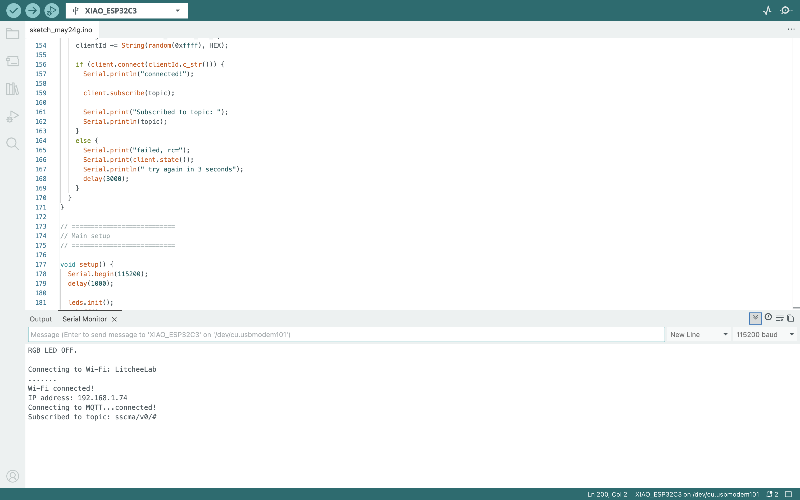
The C3 connected to Wi-Fi, connected to the MQTT broker, and
subscribed to the topic litchee/garlen/week11/apple.
When the received message contained apple, the RGB LED
turned red for five seconds.
#include <WiFi.h>
#include <PubSubClient.h>
#include <ChainableLED.h>

const char* ssid = "LitcheeLab";
const char* password = "********";

const char* mqtt_server = "broker.hivemq.com";
const int mqtt_port = 1883;
const char* topic = "litchee/garlen/week11/apple";

WiFiClient espClient;
PubSubClient client(espClient);

const int DATA_PIN = D3;
const int CLOCK_PIN = D2;

ChainableLED leds(CLOCK_PIN, DATA_PIN, 1);

void rgbOff() {
  leds.setColorRGB(0, 0, 0, 0);
  Serial.println("RGB LED OFF.");
}

void rgbRedForFiveSeconds() {
  Serial.println("Apple detected. RGB LED will stay ON for 5 seconds.");

  for (int i = 0; i < 50; i++) {
    leds.setColorRGB(0, 255, 0, 0);
    delay(100);
  }

  rgbOff();
  Serial.println("5 seconds finished.");
}
At first, the RGB LED only flashed briefly. I found that sending the color command only once was not stable enough for this module. To make the LED stay on, I repeatedly sent the red color command during the five-second output period.
Step 4: Timed MQTT Publishing Test with the S3
After the C3 receiver worked, I tested whether another board could
publish messages to the same topic. At this stage, the S3 did not use
the camera yet. I programmed the S3 to publish apple
every ten seconds. When the C3 received the message, the RGB LED
turned on for five seconds.
This was only a communication test. It proved that the S3 could publish MQTT messages and that the C3 could respond to messages from another board.
apple every ten seconds, and the C3 turned on the RGB
LED after receiving the message.
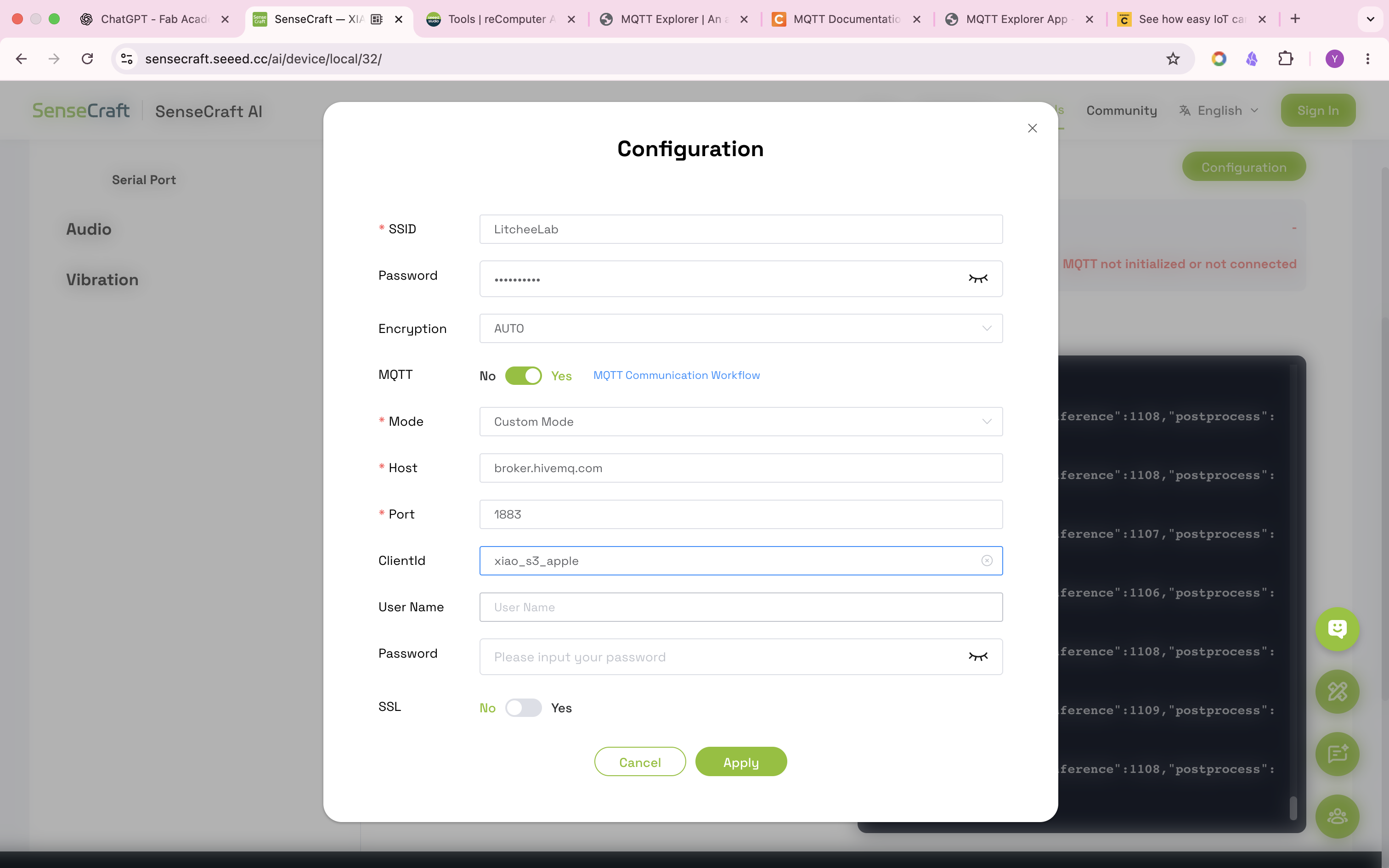
Step 5: Trying SenseCraft AI
After the basic MQTT communication worked, I started to test apple recognition on the XIAO ESP32S3 Sense. My first method was SenseCraft AI. I connected the S3 to the SenseCraft workspace and loaded an object recognition model.

The SenseCraft preview could recognize the apple successfully. The preview showed the apple label with a confidence value.
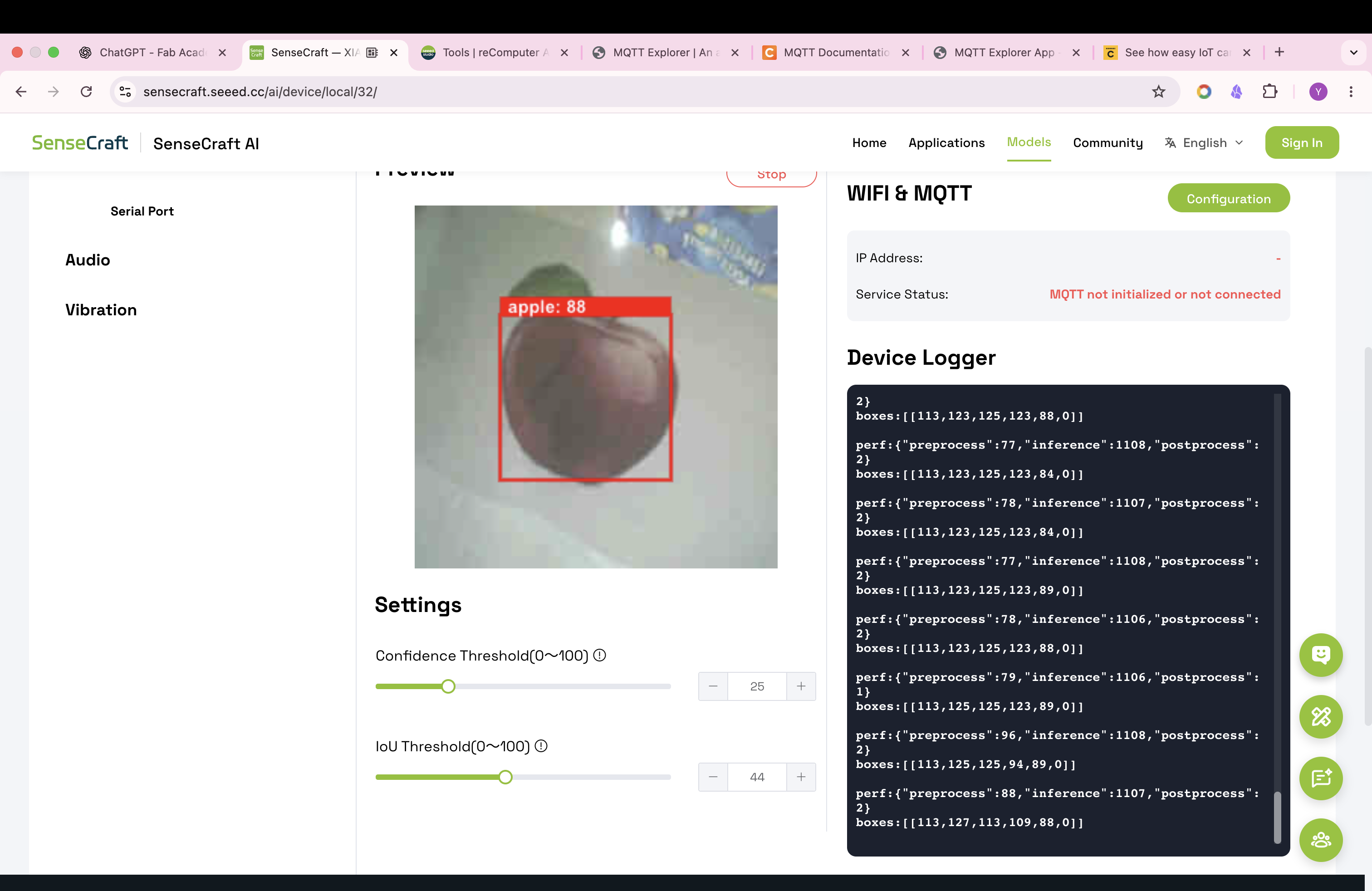
However, when I tried to use the MQTT output from SenseCraft, the
response was slower than I expected. It also used its own topic
structure, such as sscma/v0/#, which made the
communication less direct for my final test.
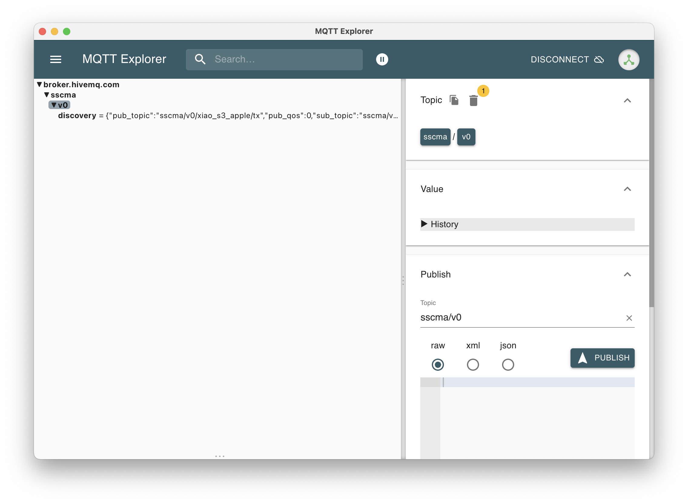
sscma/v0/# on the C3.
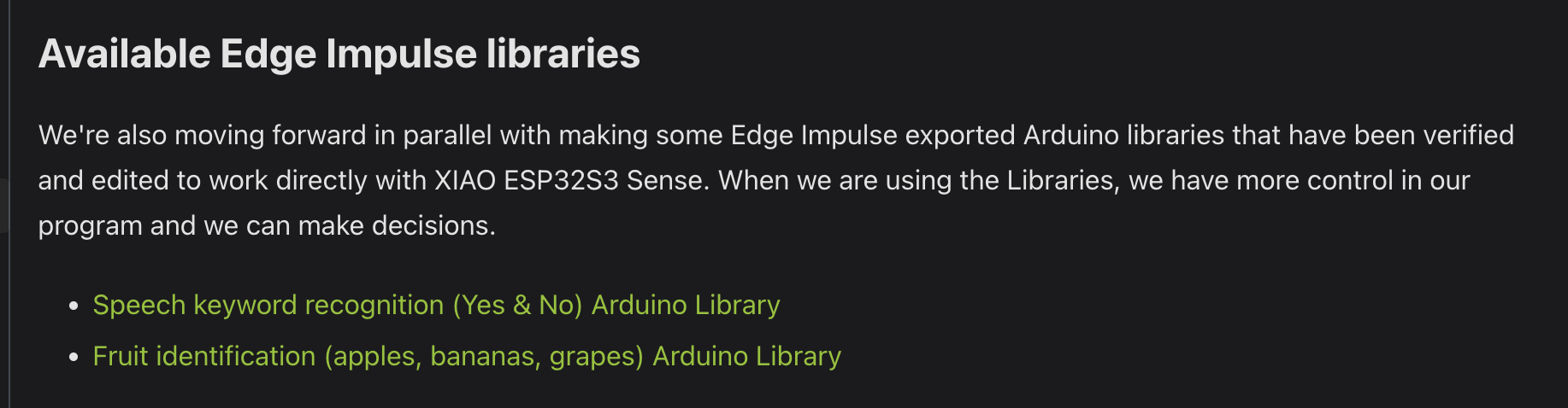
Step 6: Switching to a Local Fruit Recognition Library
To make the response faster and easier to control, I switched to a local fruit recognition Arduino library. This library can run directly on the XIAO ESP32S3 Sense and can classify apples, bananas, and grapes.
Finding the Library
I downloaded the library from the Seeed Studio Edge Impulse tutorial: Seeed Studio Wiki — Edge Impulse for XIAO ESP32S3 Sense . On this page, I found the section called Fruit identification (apples, bananas, grapes) Arduino Library.
Adding the ZIP Library to Arduino IDE
The downloaded model library file was:
xiao-esp32s3-fruits-classify_inferencing.zipI added the ZIP library to Arduino IDE through:
Sketch
→ Include Library
→ Add .ZIP Library
→ xiao-esp32s3-fruits-classify_inferencing.zip
I also uploaded the ZIP file as a source file for this week, so that the local model library can be downloaded and reused: xiao-esp32s3-fruits-classify_inferencing.zip .
../files/week_11/xiao-esp32s3-fruits-classify_inferencing.zipAfter adding the library, I could include the model in my Arduino code with:
#include <xiao-esp32s3-fruits-classify_inferencing.h>Step 7: Final Local Model and MQTT Integration
In the final version, the S3 ran the fruit recognition model locally.
The board only published apple when the model detected
apple or apples with a confidence value
higher than 0.70.
This final code did not send apple automatically every
ten seconds. The delay in the code only prevents repeated messages
when the apple stays in front of the camera.
Important S3 Code
#include <xiao-esp32s3-fruits-classify_inferencing.h>

#include <WiFi.h>
#include <PubSubClient.h>
#include "esp_camera.h"
#include "img_converters.h"
#include "edge-impulse-sdk/dsp/image/image.hpp"

const char* ssid = "LitcheeLab";
const char* password = "********";

const char* mqtt_server = "broker.hivemq.com";
const int mqtt_port = 1883;
const char* topic = "litchee/garlen/week11/apple";

WiFiClient espClient;
PubSubClient client(espClient);

void publishApple() {
  if (!client.connected()) {
    reconnect_mqtt();
  }

  client.loop();
  client.publish(topic, "apple");

  Serial.print("Published to topic: ");
  Serial.println(topic);
  Serial.println("Message: apple");
}
After the classifier ran, I checked all labels. If the label was
apple or apples, and the confidence was
higher than 0.70, the S3 published the MQTT message.
bool appleDetectedNow = false;

for (size_t ix = 0; ix < EI_CLASSIFIER_LABEL_COUNT; ix++) {
  String label = result.classification[ix].label;
  float confidence = result.classification[ix].value;

  Serial.print(label);
  Serial.print(": ");
  Serial.println(confidence, 4);

  label.toLowerCase();

  if ((label == "apple" || label == "apples") && confidence > 0.70) {
    appleDetectedNow = true;
  }
}

if (appleDetectedNow) {
  Serial.println("Apple detected by local AI model.");

  if (millis() - lastAppleSendTime > resendDelay) {
    publishApple();
    lastAppleSendTime = millis();
  }
}
Final Test
In the final test, I placed an apple in front of the S3 camera. The
local fruit model detected the apple, the S3 published the MQTT
message apple, and the C3 received the message and
turned on the RGB LED for five seconds.
Result
The final system worked successfully. The S3 recognized the apple locally and sent an MQTT message. The C3 received the message and controlled the RGB LED as the output device.
Problems and Solutions
| Problem | Reason | Solution |
|---|---|---|
| MQTT Explorer was blocked by macOS. | The manually downloaded app could not be opened. | I downloaded MQTT Explorer directly from the App Store. |
PubSubClient.h could not be found. |
The MQTT library was not installed in Arduino IDE. | I installed the PubSubClient library from the Arduino Library Manager. |
| The C3 could not connect to Wi-Fi at first. | The first Wi-Fi network was not suitable for the ESP32 board. |
I changed the Wi-Fi to LitcheeLab, and the C3
connected successfully.
|
| The RGB LED only flashed briefly. | Sending the RGB color command only once was not stable enough for this Grove RGB LED module. | I repeatedly sent the red color command during the five-second lighting period. |
| The S3 timed publish test was not the final goal. | It only tested communication, not apple recognition. | I replaced the timed publish logic with model-based publishing. |
| SenseCraft AI MQTT output was slow. | SenseCraft used its own MQTT topic structure and the response was delayed in my test. | I switched to a local fruit recognition Arduino library and published my own MQTT message from the S3. |
| The S3 upload port was busy. | The Serial Monitor or SenseCraft browser page was still connected to the board. | I closed the Serial Monitor and SenseCraft page, unplugged and replugged the S3, then uploaded again. |
The S3 showed Failed to allocate snapshot buffer. |
The camera and AI model required more memory than normal internal RAM could provide. |
I enabled PSRAM in Arduino IDE and allocated the image buffer in
PSRAM using ps_malloc().
|
What I Learned
This week helped me understand how to test a networked system step by step. Instead of trying to build the final system immediately, I first tested the MQTT tool, then the C3 receiver, then S3 publishing, then image recognition, and finally the complete integration.
I learned that MQTT is useful because the sender and receiver do not need to be directly connected. They only need to use the same broker and topic. This makes the system flexible and easier to debug.
I also learned that running camera recognition on the XIAO ESP32S3 Sense requires careful memory management. Enabling PSRAM was important for making the camera and local model work together.
References and AI Use Statement
References and tutorials
I used several references and tutorials during this week. MQTT Explorer was used as the MQTT testing software. I used it to view topics and manually publish test messages during debugging.
- MQTT Explorer official website: https://mqtt-explorer.com/
- HiveMQ Public MQTT Broker: https://www.hivemq.com/mqtt/public-mqtt-broker/
- Seeed Studio Wiki — Edge Impulse for XIAO ESP32S3 Sense: https://wiki.seeedstudio.com/edgeimpulse/
- Seeed Studio Wiki — SenseCraft AI model output via MQTT: https://wiki.seeedstudio.com/sensecraft-ai/tutorials/sensecraft-ai-output-mqtt-xiao/
- Seeed Studio Wiki — Using a model for XIAO ESP32S3 Sense: https://wiki.seeedstudio.com/sensecraft-ai/tutorials/sensecraft-ai-pretrained-models-for-xiao/
I used the Seeed Studio Edge Impulse tutorial to find and download the fruit identification Arduino library. This library was used as the local model on the XIAO ESP32S3 Sense. I also uploaded the downloaded ZIP file as a source file for this week:
../files/week_11/xiao-esp32s3-fruits-classify_inferencing.zipAI use statement
I used AI as a helper during this week. AI helped me understand the MQTT workflow, compare the SenseCraft AI method and the local model method, debug Arduino error messages, and organize the documentation into a clear step-by-step process.
Some parts of the Arduino code structure were written with AI help, especially the MQTT publishing and receiving logic. I edited the code for my own Wi-Fi, MQTT topic, pins, and test behavior. I also tested the code myself on the XIAO ESP32S3 Sense and XIAO ESP32-C3 boards.
AI was also used to help polish the English writing and HTML structure of this documentation. The physical wiring, MQTT Explorer tests, SenseCraft AI tests, local model tests, serial monitor checks, and final videos were completed and verified by myself.
Reflection
This week connected several previous topics together: input devices, output devices, embedded programming, and networking. The S3 acted as a smart input node, while the C3 acted as a physical output node.
The most important part was not only sending an MQTT message, but
deciding when the message should be sent. The final system only sent
apple after the local model detected an apple, instead of
sending messages at a fixed time interval.
For my final project, this workflow is very useful. My emotional companion robot may need to recognize visual information and trigger a physical response, such as light, movement, or sound. This week's test gives me a basic structure for that kind of interaction.