Overview
This week was about output devices. Output devices allow a microcontroller to create a physical response, such as light, sound, movement, heat, or vibration. Compared with input devices, which read information from the environment, output devices make the system act on the physical world.
I first tested a single LED blink. This was a simple check of the digital output pin on my PCB. The LED turned on and off every second.
For my main output test, I used an LED module. The LED was controlled by a line finder sensor. When the sensor detected a black surface, the LED turned on. When the sensor detected a white surface, the LED turned off.
I also tested a servo motor as another output device. This experiment helped me understand that motor outputs require more careful power planning than LED outputs. The servo required more current, so I used an external 5V power supply through a breadboard.
Assignment
Group Assignment
The group assignment was to observe and measure the electrical behavior of an output device. For this assignment, I used an LED module because it was a stable and safe output device for measurement. I measured the voltage between VCC and GND to check whether the LED output device received a stable supply voltage.
Individual Assignment
The individual assignment was to add an output device to a microcontroller board that I designed and program it to do something. I connected an LED module to my XIAO ESP32-C3 board and programmed it to respond to a line finder sensor.
Group Assignment
Measuring the Supply Voltage of an LED Output Device
For the group assignment, I measured the supply voltage of an LED output module. At first, I considered using a servo motor, but the servo required a larger current and caused unstable power behavior. Therefore, I used the LED module as the formal output device for this measurement.
The LED module was safer and more stable to test. I used a multimeter to measure the voltage between VCC and GND. This helped me check whether the output device was receiving a stable supply voltage from the board.
In this test, I focused on voltage measurement instead of current measurement. Although power consumption is usually calculated from both voltage and current, this voltage test was still useful for understanding the basic electrical condition of the LED output device.
Measuring VCC and GND on the Board
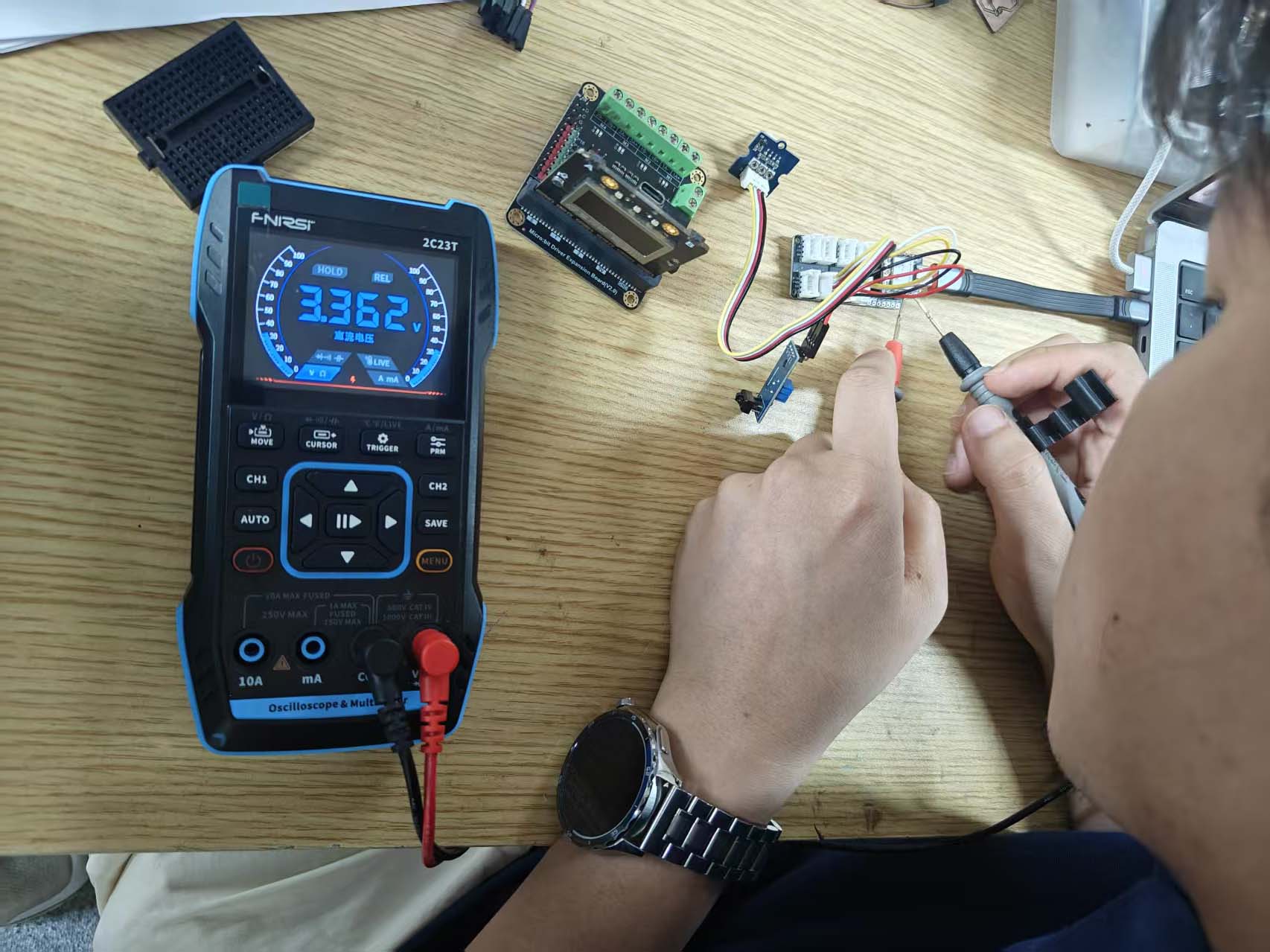
First, I measured the voltage between VCC and GND on the board. The multimeter was set to DC voltage mode. The red probe was connected to VCC, and the black probe was connected to GND.
Measuring VCC and GND of the LED Module
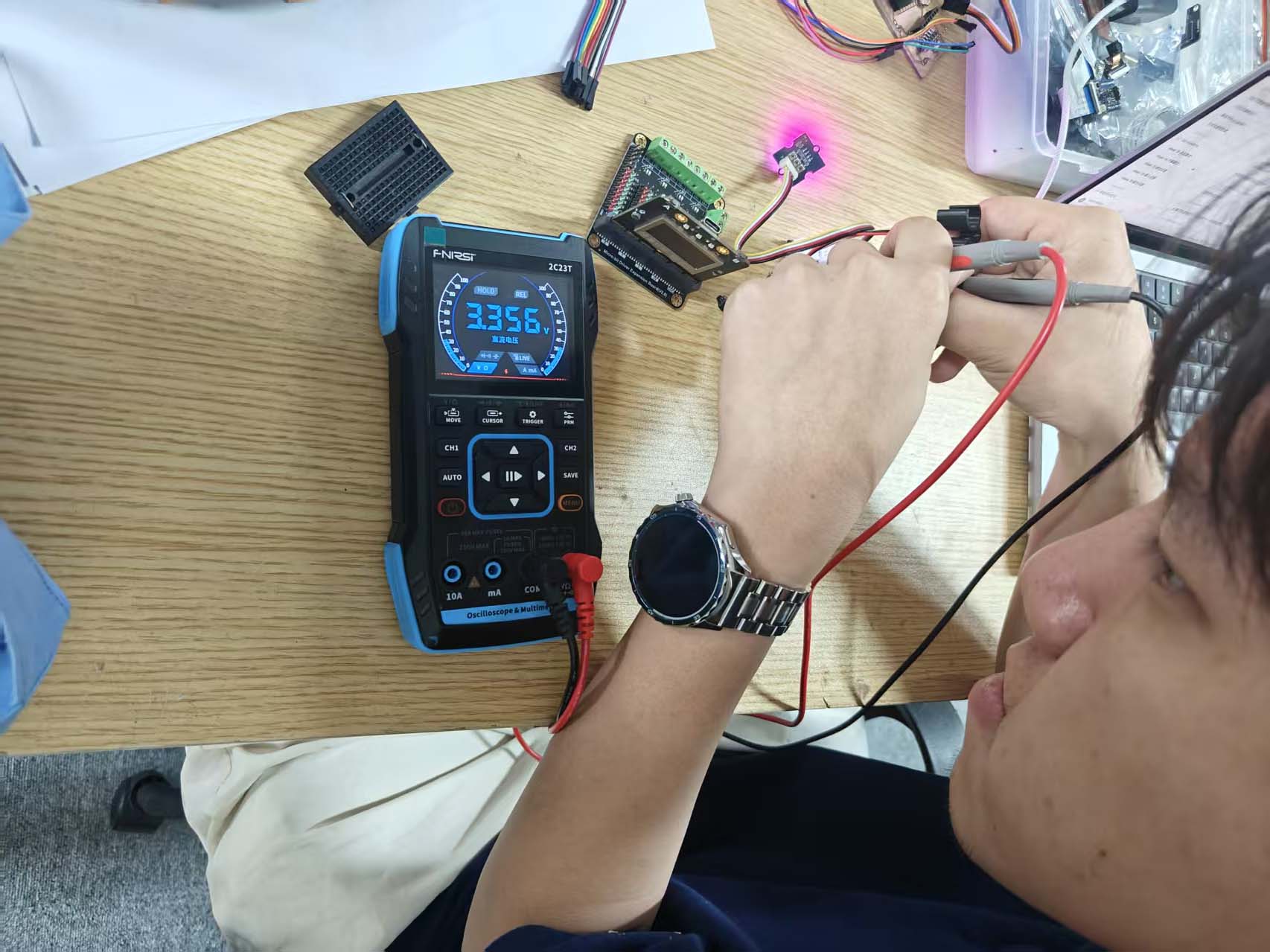
Then, I measured the voltage of the LED module itself. My own PCB did not have the same connector type for this LED module, so I used another compatible board for this measurement. This allowed me to connect the LED module correctly and measure the voltage between its VCC and GND pins.
This compatible board was only used for the voltage measurement because of the connector type. For the output control test, I still used my XIAO ESP32-C3 board as the microcontroller board.
| Output device | Measurement point | Measured value | Tool |
|---|---|---|---|
| LED module | Board VCC and GND | About 3.32V | Multimeter |
| LED module | LED module VCC and GND | About 3.56V | Multimeter |
Group Assignment Result
Through this measurement, I confirmed that the LED output device received a stable supply voltage. The board VCC and GND measured about 3.32V, and the LED module VCC and GND measured about 3.56V in my test setup.
This test helped me understand the basic power condition of a simple output device. Compared with the servo motor, the LED module was much easier and safer to measure because it required less current and did not cause unstable power behavior.
Individual Assignment
For my individual assignment, I made two output tests. First, I tested a single LED blink. Then, I used a line finder sensor to control an LED module.
Output Test 01: Basic LED Blink
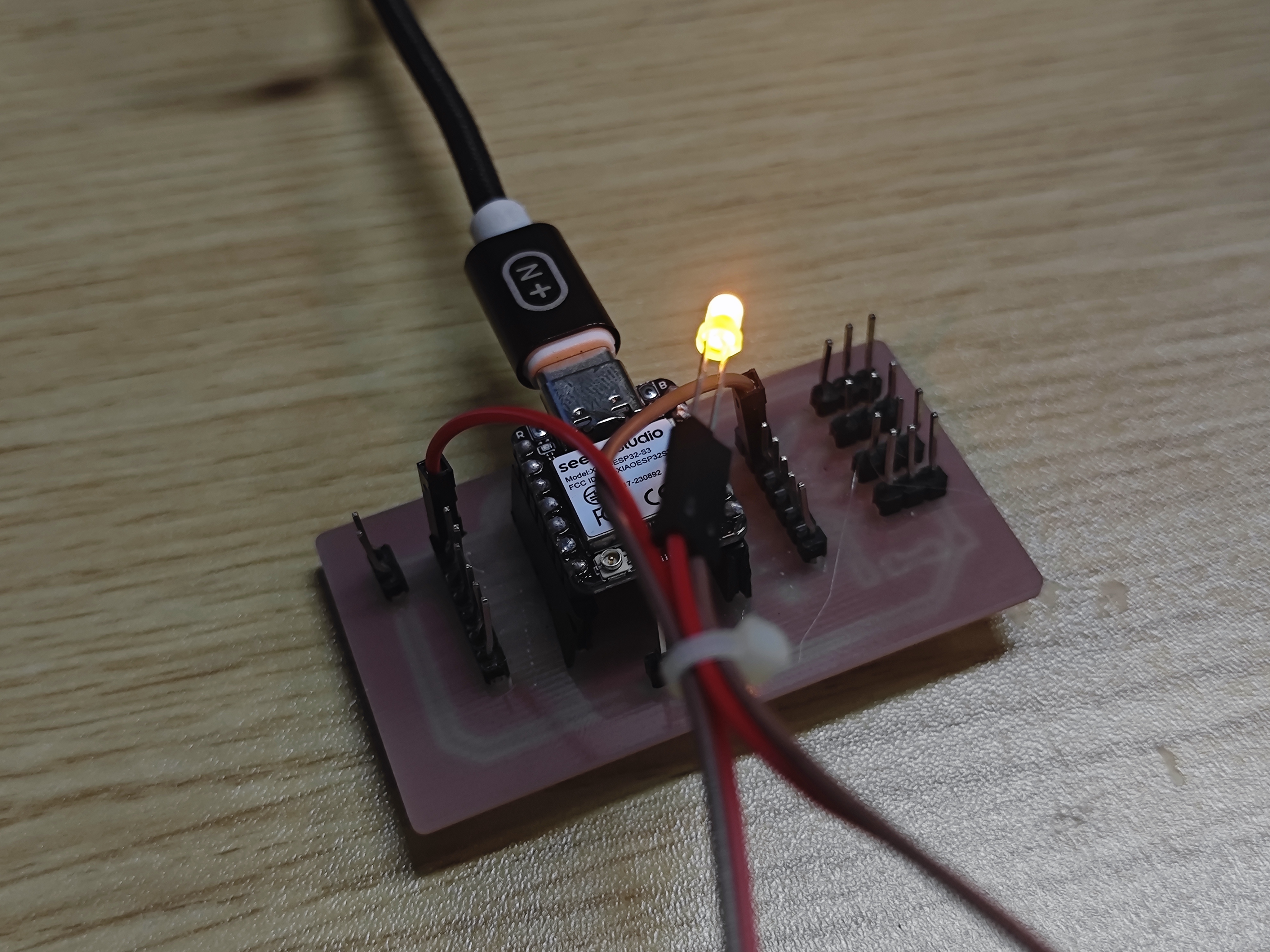
I started with a very simple LED blink test. This helped me check that the digital output pin on my PCB worked correctly.
The LED was connected to GPIO 1. The code turned the LED on for one second, and then turned it off for one second.
This test was useful before making a more complex sensor-controlled output. It confirmed that the board could send a stable digital output signal.
const int ledPin = 1;

void setup() {
  pinMode(ledPin, OUTPUT);
}

void loop() {
  digitalWrite(ledPin, HIGH);  // Turn LED on
  delay(1000);

  digitalWrite(ledPin, LOW);   // Turn LED off
  delay(1000);
}Output Test 02: Line Finder Controlled LED Output
For my main individual assignment, I connected an LED module to my XIAO ESP32-C3 board and programmed it to respond to a line finder sensor. The line finder sensor was used as an input trigger, and the LED module was used as the output device.
The logic of the test was simple: when the line finder detected a black surface, the LED turned on. When the sensor detected a white surface, the LED turned off.
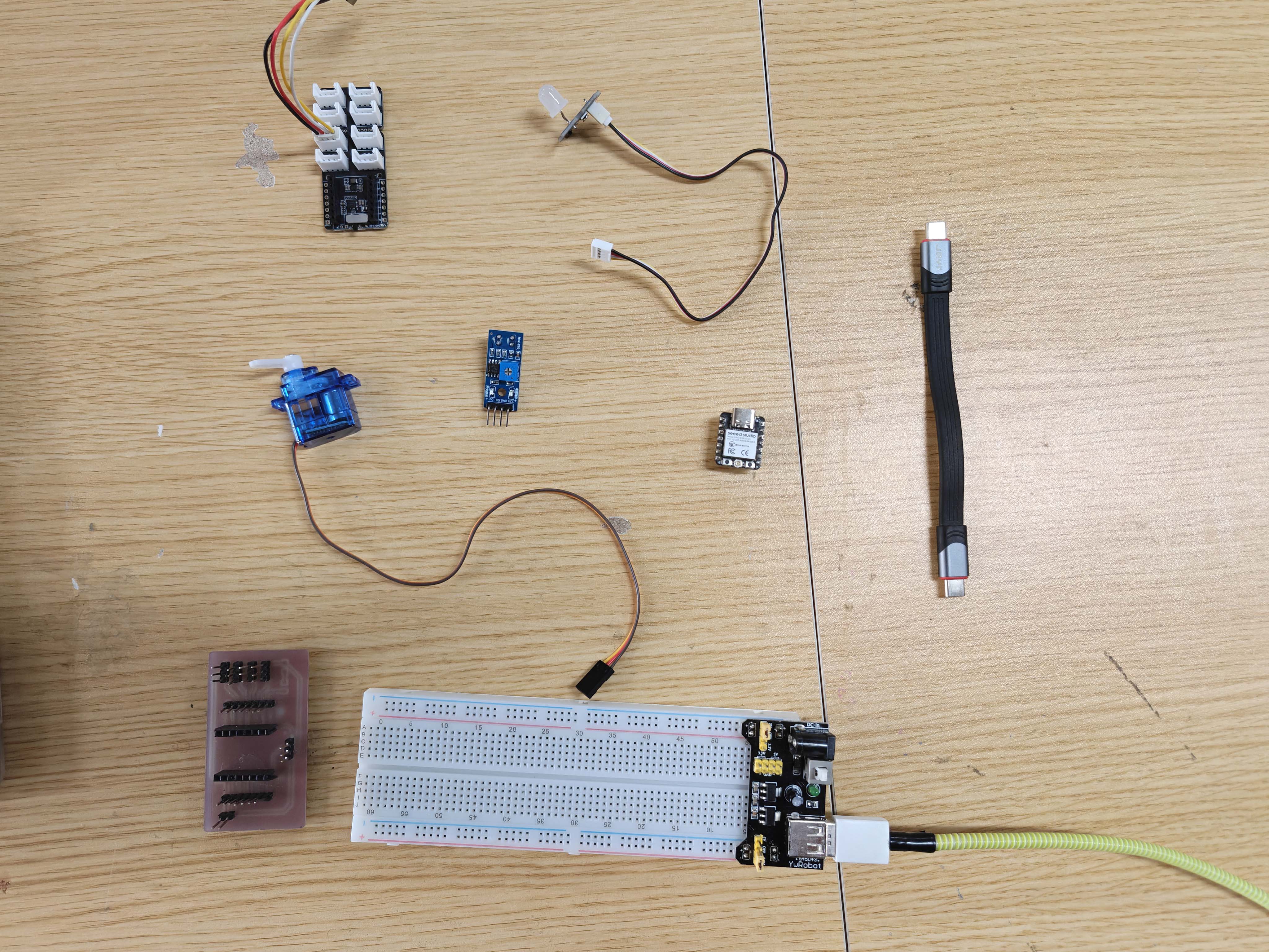
Components
- XIAO ESP32-C3 board
- My own XIAO ESP32-C3 PCB
- Line finder sensor
- LED module
- Single LED
- Servo motor
- Breadboard power module
- Breadboard
- USB cable
- Jumper wires
Wiring
The line finder sensor has both AO and DO pins. In this test, I used the DO pin as a digital input signal. The LED module was connected to another digital output pin on the XIAO ESP32-C3.
In my setup, the line finder module used two signal pins. Pin 1 was AO, and pin 2 was DO. The LED module was connected to another port, and I used D3 as the LED signal pin.
| Line finder sensor | XIAO ESP32-C3 | Function |
|---|---|---|
| VCC | 3.3V | Power |
| GND | GND | Ground |
| AO | D1 | Analog output, observed but not used for LED control |
| DO | D2 | Digital output used for black / white detection |
| LED module | XIAO ESP32-C3 | Function |
|---|---|---|
| VCC | 3.3V | Power |
| GND | GND | Ground |
| Signal | D3 | Digital output control |
Line Finder VCC  → XIAO ESP32-C3 3.3V
Line Finder GND  → XIAO ESP32-C3 GND
Line Finder AO   → XIAO ESP32-C3 D1
Line Finder DO   → XIAO ESP32-C3 D2

LED VCC          → XIAO ESP32-C3 3.3V
LED GND          → XIAO ESP32-C3 GND
LED Signal       → XIAO ESP32-C3 D3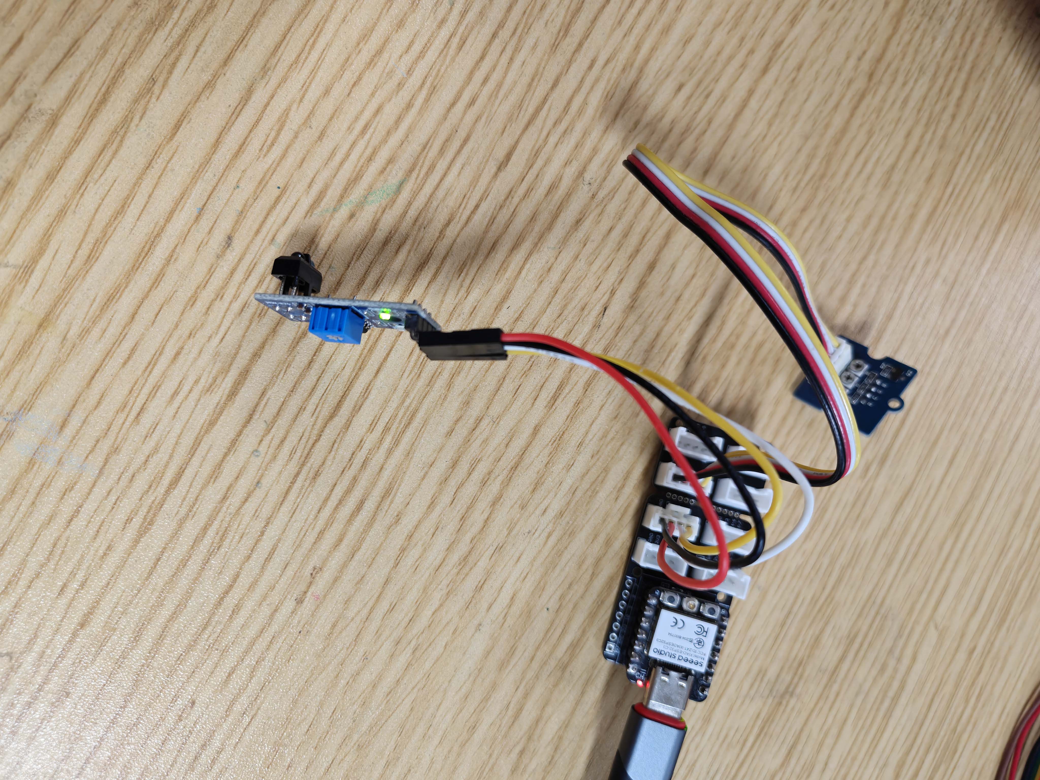
Arduino Code
I used the following Arduino code to read the digital output from the line finder sensor and control the LED module. In my test, the line finder output was 1 when it detected a black surface, so the LED was turned on when the digital value was 1.
const int lineFinderDO = D2;  // Line finder DO connected to D2
const int ledPin = D3;        // LED signal connected to D3

void setup() {
  Serial.begin(115200);

  pinMode(lineFinderDO, INPUT);
  pinMode(ledPin, OUTPUT);

  Serial.println("Line Finder controls LED");
}

void loop() {
  int lineValue = digitalRead(lineFinderDO);

  Serial.print("DO: ");
  Serial.println(lineValue);

  // In my test:
  // DO = 1 means black surface
  // DO = 0 means white surface
  if (lineValue == 1) {
    digitalWrite(ledPin, HIGH);  // Black surface: LED on
  } else {
    digitalWrite(ledPin, LOW);   // White surface: LED off
  }

  delay(100);
}
Testing Process
After connecting the line finder sensor and the LED module, I uploaded the Arduino code to the XIAO ESP32-C3 board. I opened the Arduino Serial Monitor to check the digital value from the line finder sensor.
In my test, when the line finder detected a black surface, the Serial Monitor showed DO = 1, and the LED turned on. When the sensor detected a white surface, the Serial Monitor showed DO = 0, and the LED turned off.
Result
The LED output test worked successfully. The XIAO ESP32-C3 read the digital signal from the line finder sensor and used this value to control the LED module. This confirmed that my board could control a physical output device through code.
This experiment also helped me understand how an input signal can be translated into an output behavior. The line finder detected the surface condition, and the LED gave a visible response.
Additional Output Test
Servo Motor Test with External Power on Breadboard
I also tested a servo motor as another output device. At first, I tried to power the servo directly from the board, but the servo required too much current and caused unstable power behavior. During this process, one USB-C port on my computer stopped working, possibly because of unstable power behavior. After that, I became more careful about separating the servo power supply from the microcontroller power supply.
To solve this problem, I used a breadboard and an external 5V power supply for the servo motor. In this setup, the XIAO ESP32-C3 only sent the control signal to the servo, while the servo motor received power from the external 5V supply.
Servo Wiring with External Power
The most important rule in this setup was common ground. The external power supply GND had to be connected to the XIAO ESP32-C3 GND. However, the external 5V should not be connected directly to the 3.3V pin of the microcontroller.
| Servo motor | Connection |
|---|---|
| Red wire | External 5V on breadboard power rail |
| Black / Brown wire | External GND on breadboard power rail |
| Yellow / Orange signal wire | XIAO ESP32-C3 D1 / A1 |
External 5V +      → Breadboard + rail
External GND -     → Breadboard - rail

Servo red wire     → Breadboard + rail
Servo black wire   → Breadboard - rail
Servo signal wire  → XIAO ESP32-C3 D1 / A1

XIAO ESP32-C3 GND  → Breadboard - rail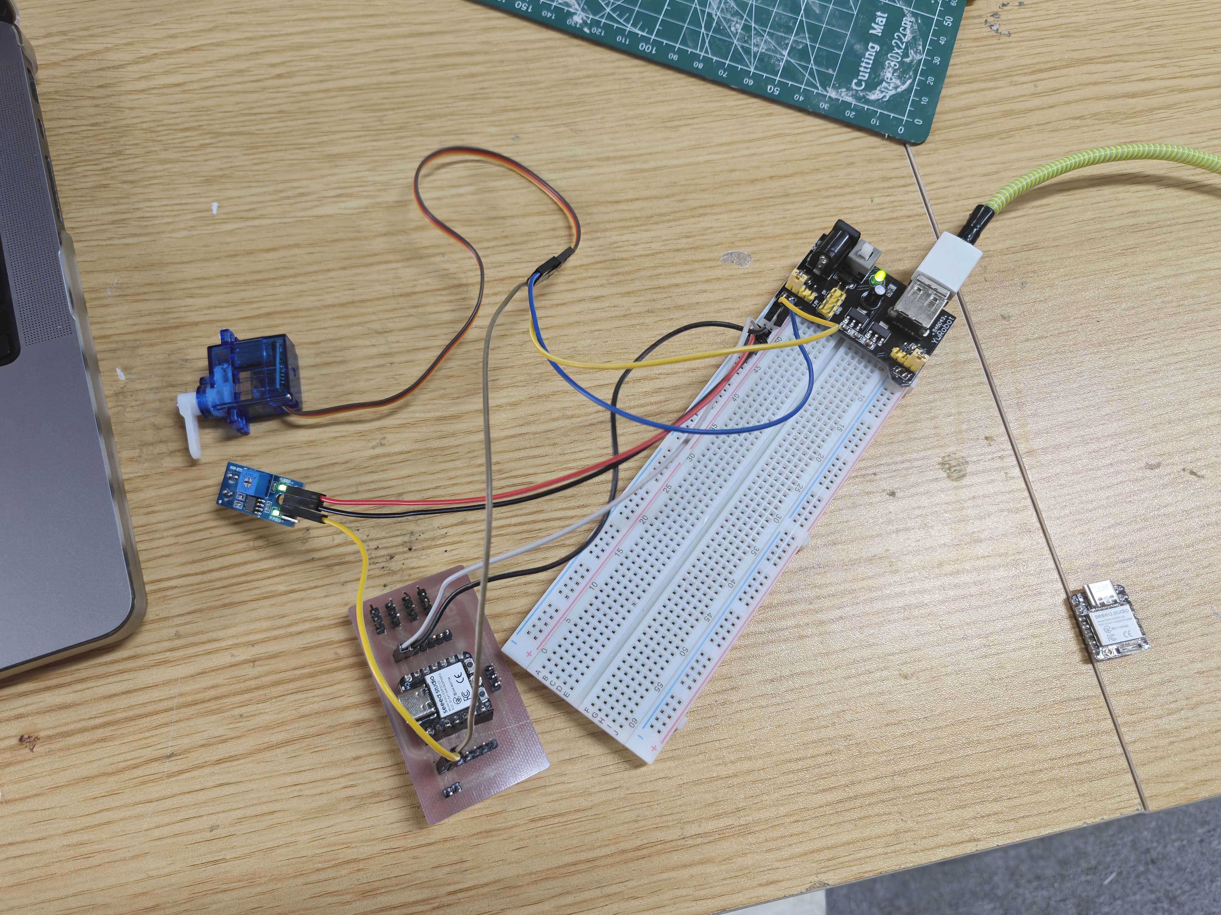
Servo Test Code
I used the ESP32Servo library to test the servo movement. The movement range was kept small to reduce current spikes and make the test more stable.
#include <ESP32Servo.h>

Servo myServo;

const int servoPin = D1;  // Servo signal connected to D1 / A1

void setup() {
  myServo.setPeriodHertz(50);
  myServo.attach(servoPin, 500, 2500);
}

void loop() {
  myServo.write(70);
  delay(800);

  myServo.write(110);
  delay(800);
}
Servo Test Result
This test helped me understand why motors are more difficult to power than simple LED modules. The LED module could be powered directly from the microcontroller board, but the servo motor needed a separate 5V power source to avoid voltage drops and reset problems.
Because of this, I used the LED module for the formal group measurement, and kept the servo motor as an additional output device test.
Problems and Solutions
| Problem | Reason | Solution |
|---|---|---|
| The servo motor caused unstable power behavior. | The servo required more current than the microcontroller board could safely provide. When the servo moved, the voltage could drop and cause reset or power problems. | I stopped powering the servo directly from the board. Instead, I used an external 5V supply on a breadboard and connected the external GND to the XIAO ESP32-C3 GND. |
| The servo did not respond correctly at first. | The servo had power, but the signal needed a common ground between the external power supply and the microcontroller. | I connected the external GND to the XIAO ESP32-C3 GND and kept the external 5V separate from the board power. |
| The LED module could not be measured on my own PCB connector. | My own PCB did not have the same connector type for the LED module. | I used another compatible board to connect the LED module and measure the voltage between VCC and GND. |
| The LED did not respond correctly at first. | The LED module and the line finder sensor needed to use different digital pins. | I connected the line finder DO to D2 and the LED signal to D3, and then updated the Arduino code to match the wiring. |
| The line finder logic needed confirmation. | The digital output depends on the surface and the sensor threshold setting. | I used the Serial Monitor to confirm that black corresponded to DO = 1 and white corresponded to DO = 0 in my setup. |
What I Learned
This week helped me understand how microcontrollers control output devices. A simple LED module can be controlled directly with a digital output pin, while a servo motor needs a PWM signal and more careful power management.
I also learned the difference between signal control and power supply. For the LED module, the power requirement was small, so it could be powered directly from the board. For the servo motor, the microcontroller only provided the signal, while an external 5V supply provided the motor power.
The most important lesson was common ground. When using an external power supply for an output device, the external GND and the microcontroller GND must be connected together. Otherwise, the output device may not respond correctly to the control signal.
Reflection
Compared with input devices, output devices made the result more visible and physical. The line finder controlled LED test showed a clear relationship between sensing and output: the sensor detected the surface, and the LED responded immediately.
The servo test was also useful, even though I did not use the servo for the formal group measurement. It showed that motors are more demanding than simple electronic modules. A servo motor can create movement, but it also requires more current and more careful wiring.
For my final project, this week is directly useful. My emotional companion robot will need both light output and movement output. The LED test can be developed into visual feedback, while the servo test can be developed into ear or tail movement.
AI Use Statement
I used AI to help organize my Week 10 documentation. It helped me write clearer English sentences and structure the page. I also used AI to check how to explain output devices, servo power, and LED control.
AI helped me understand the Arduino error about the missing ESP32Servo library. It also helped me plan the testing order. I first tested a basic LED blink. Then I tested the line finder controlled LED output. Finally, I added the servo motor test as an extra output experiment.
All physical wiring, soldering, testing, measuring, photos, and videos were done by me. AI was only used as a writing and debugging assistant. I checked the final content and changed it to match my real process.