Overview
This week was about CNC machining.
CNC machining cuts material with a rotating tool.
It can cut thicker material than a laser cutter.
It also needs more safety preparation.
I made a shell chair from wooden sheet material.
The chair used ribs, side frames, slots, and curved parts.
Assignment
Group Assignment
We reviewed CNC safety and tested the machine.
We checked runout, alignment, fixturing, speeds, feeds, and toolpaths.
Individual Assignment
I had to design, mill, and assemble something big.
I chose to make a CNC-milled shell chair.
Group Assignment
CNC safety training and machine test
For the group assignment, we first reviewed the safety rules for using the CNC router. CNC machining can be dangerous because the spindle rotates at high speed and the machine moves with strong cutting force. Before operating the machine, it is important to understand the emergency stop button, machine boundary, material fixation, tool installation, dust collection, and safe body position.
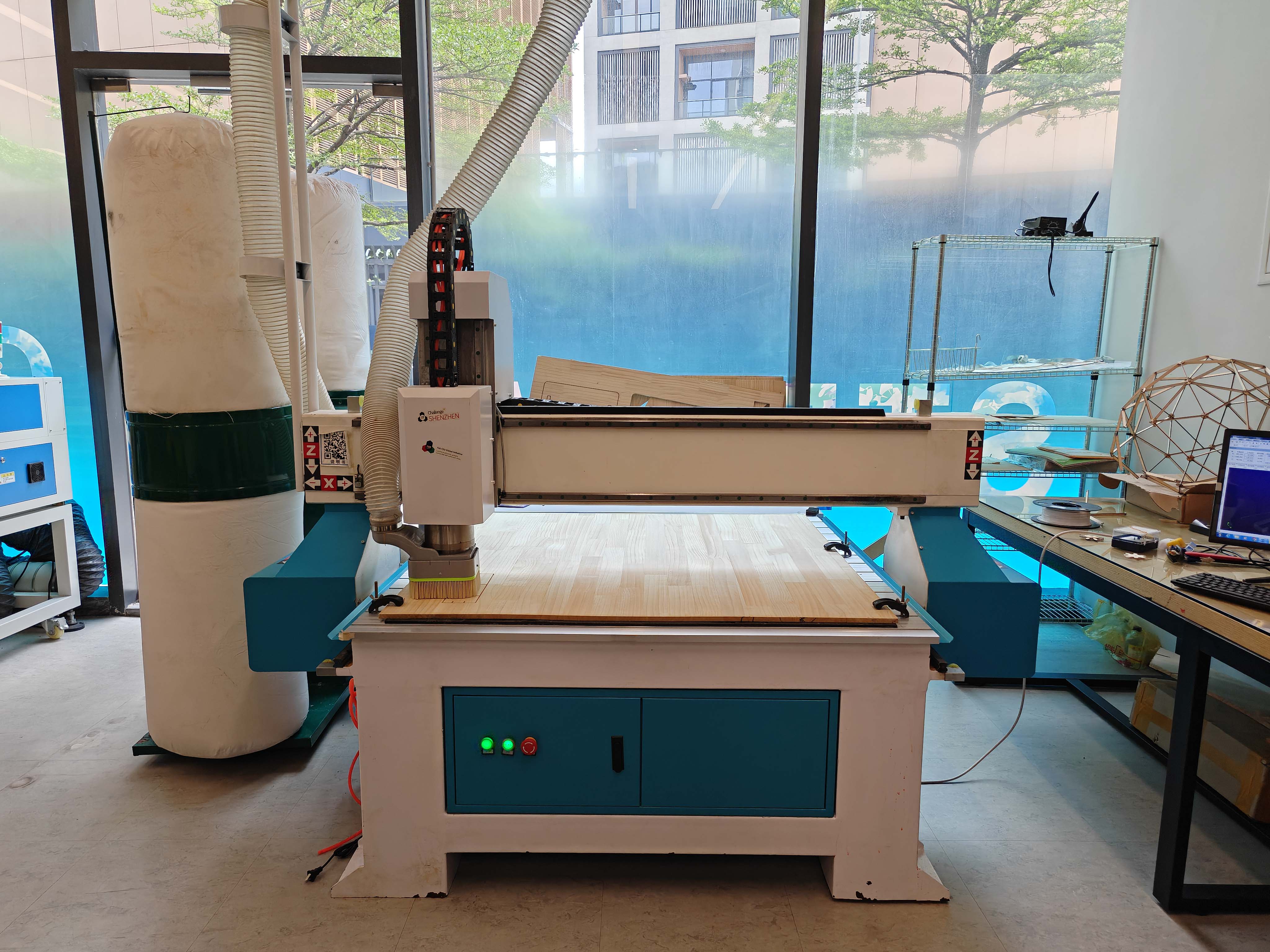
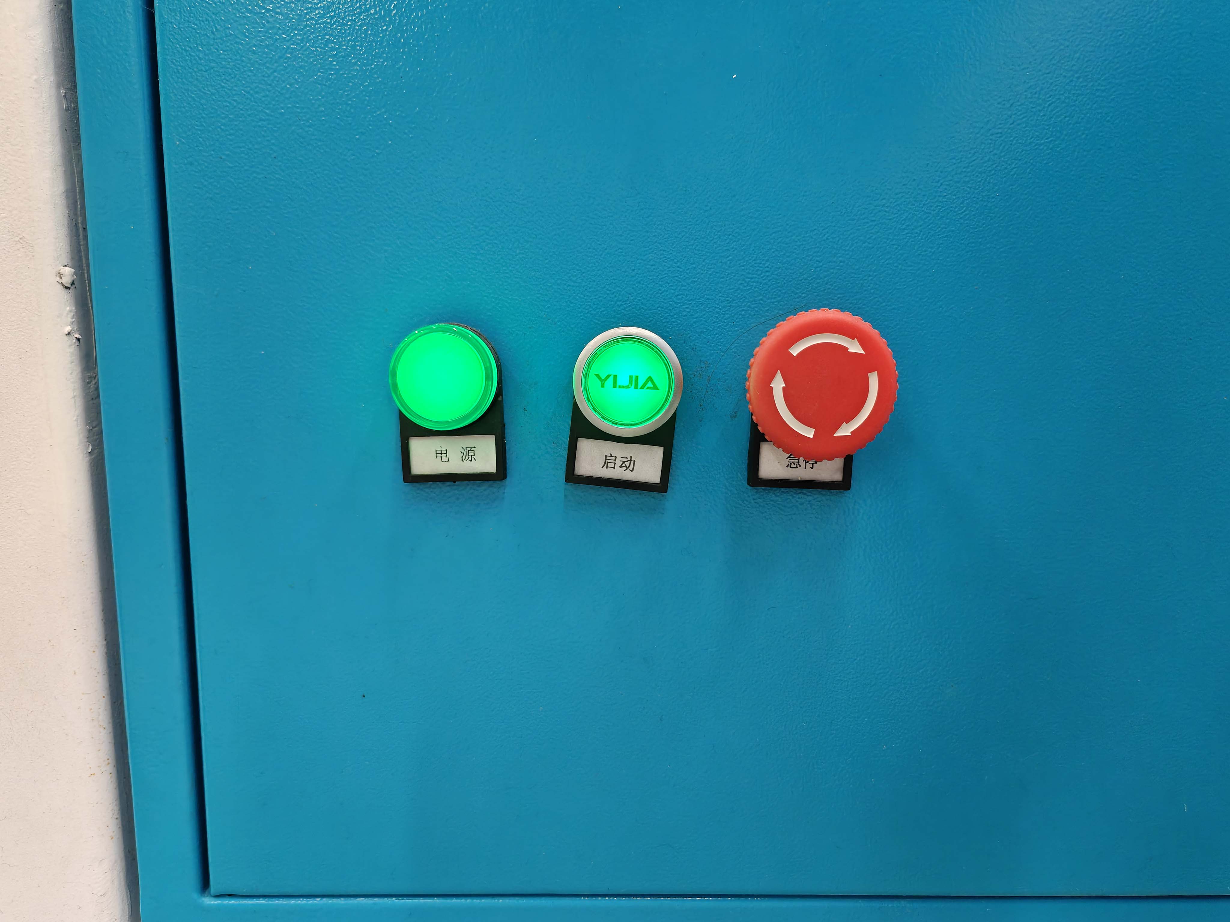
We checked the control area of the machine before starting the job. The emergency stop button is one of the most important safety controls. I needed to know where it was and make sure I could stop the machine quickly if anything went wrong.
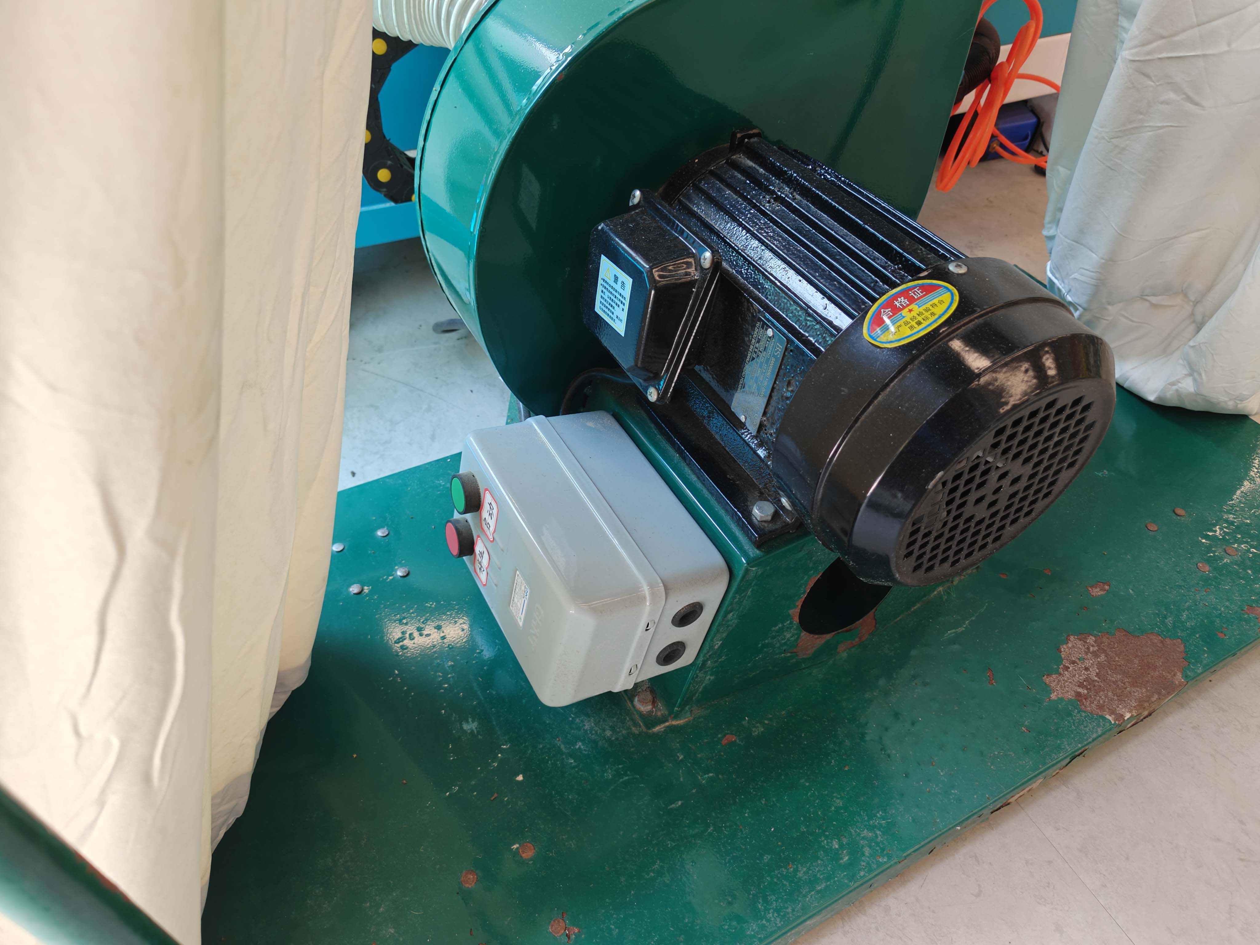
The CNC router was connected to a dust collection system. This is very important when cutting wood-based materials because the process produces a large amount of chips and dust.
Safety checklist
- Wear safety glasses during machine operation.
- Keep loose clothes, long hair, and accessories away from the machine.
- Do not wear gloves near a rotating spindle.
- Check the emergency stop button before starting.
- Fix the material firmly to the machine bed.
- Check that the tool is properly installed.
- Turn on dust collection when cutting wood-based material.
- Never leave the CNC machine unattended while it is cutting.
- Look, listen, and smell during machining to detect problems early.
Machine test
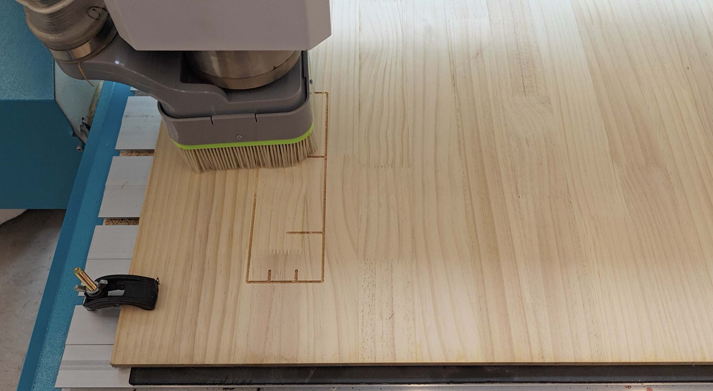
Before cutting the final design, I first made a small test cut on the wooden sheet. This test helped me check whether the material was fixed properly, whether the toolpath direction was correct, and whether the CNC machine could cut the board cleanly.
This step was important because CNC machining is not only about the digital file. The actual result also depends on the tool, the material, the cutting depth, the feed speed, and the fixation of the board.
| Test item | Purpose | Observation |
|---|---|---|
| Runout | To check whether the rotating tool is centered and stable. | A stable tool rotation helps improve cutting accuracy. |
| Alignment | To check the relationship between machine axes and the material. | The material must be squared and aligned before cutting. |
| Fixturing | To prevent the material from moving during machining. | The sheet must be fixed firmly before starting the job. |
| Speeds and feeds | To test the cutting quality and machine stability. | Incorrect settings can cause chatter, burning, or poor edge quality. |
| Toolpaths | To compare inside cuts, outside cuts, and cutting order. | Toolpath order and offset direction directly affect the final fit. |
Individual Assignment
Designing and making a CNC-milled shell chair
For this assignment, I made a chair from a wooden sheet.
The chair was inspired by the classic Shell Chair.
I liked its open side frame and curved seat.
I did not copy it directly.
I changed the armrests and side profile.
I wanted the shape to feel calmer and more like Song dynasty furniture.
Design workflow
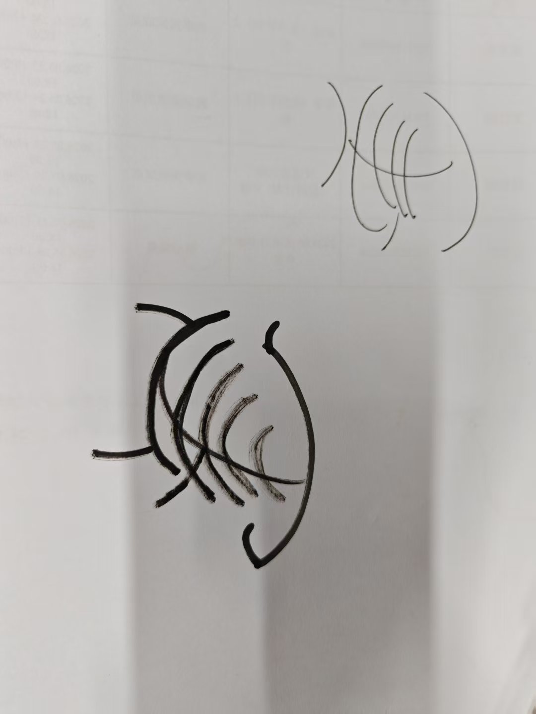
I started with a quick sketch.
The sketch helped me test the shell-like seat and rib direction.
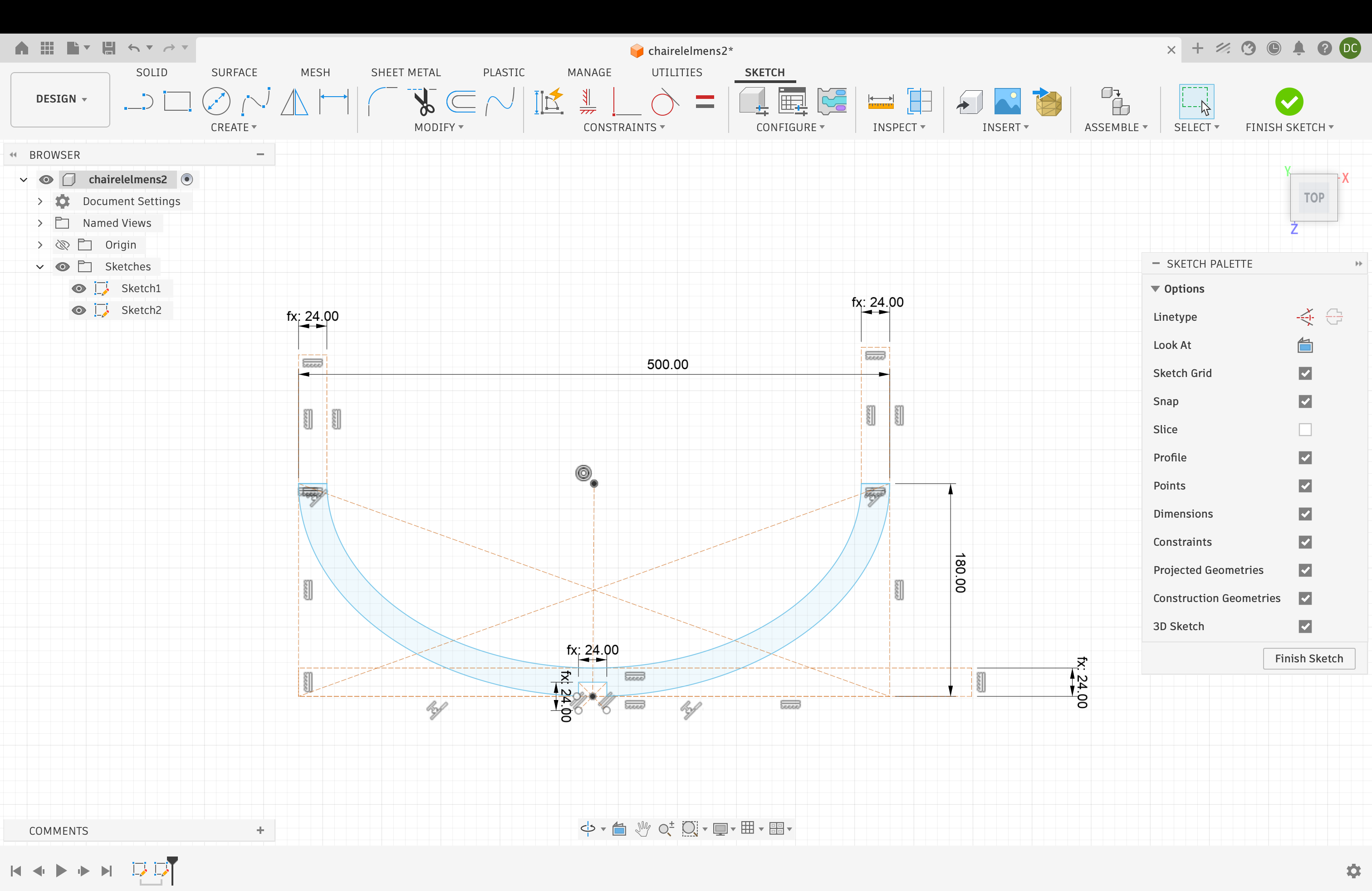
Then I rebuilt the parts in Fusion 360.
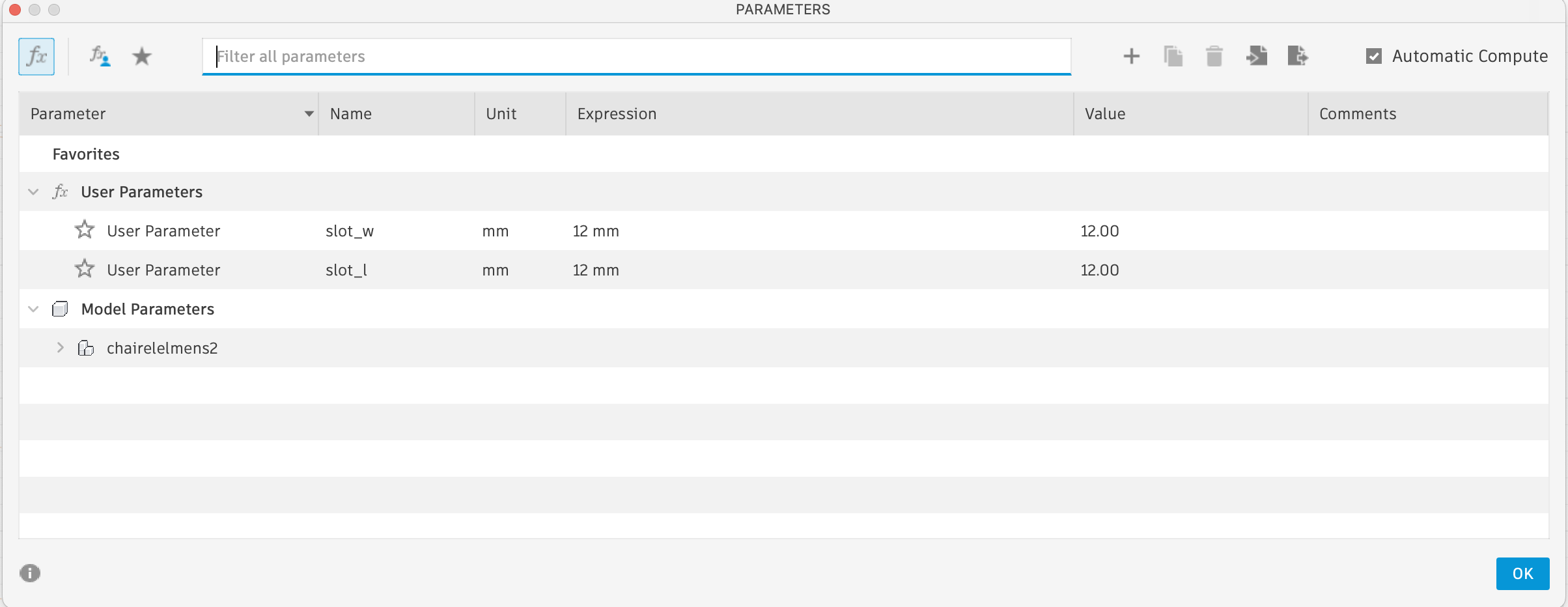
I used parameters for the slots.
The board thickness was 12 mm.
So I set slot_w and slot_l to 12 mm.
I drew the armrest as a separate sketch area.
This made the upper curve easier to control.
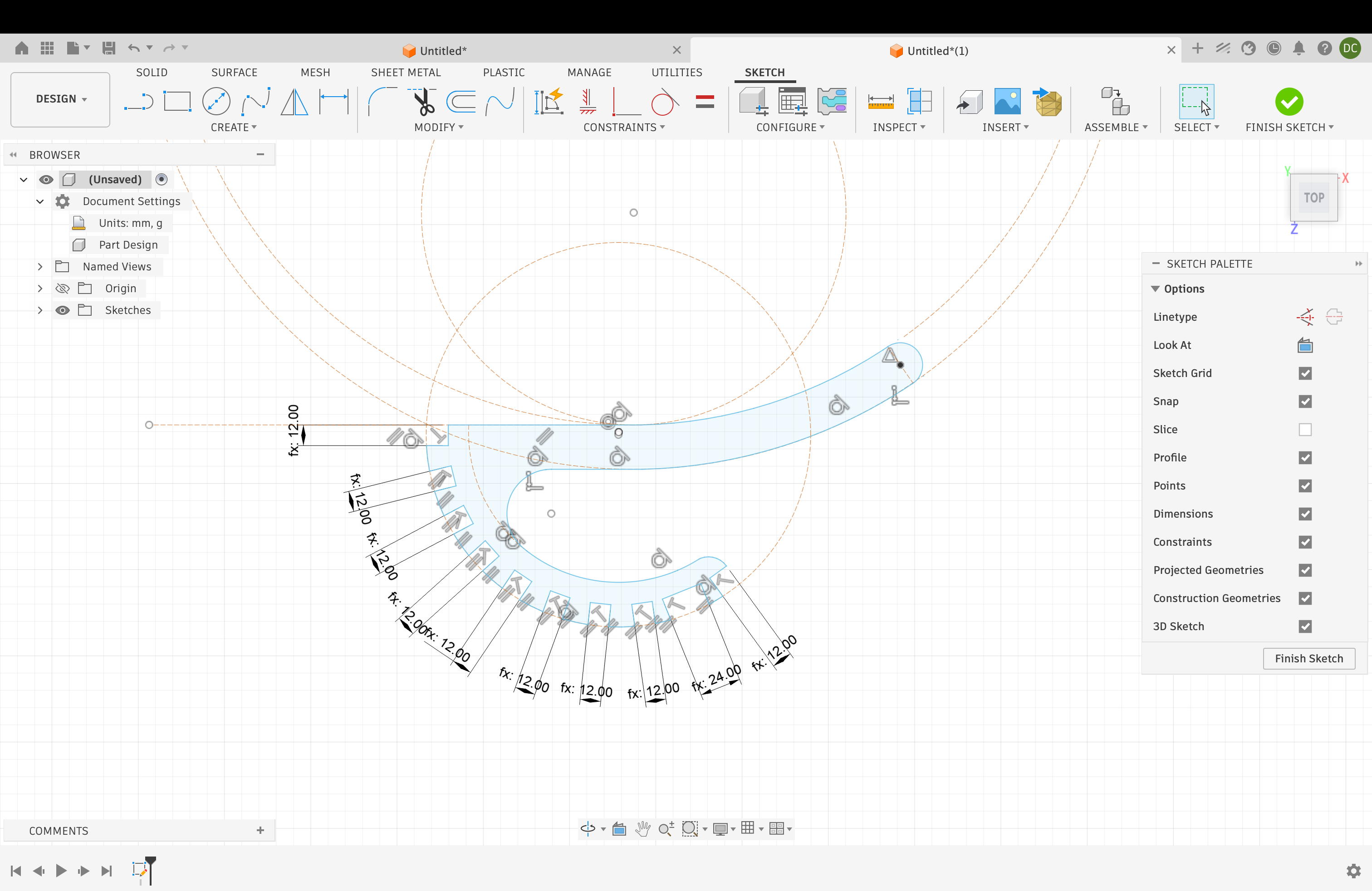
I also drew the seat curve with dimensions.
This helped me control the width, height, and center slot.
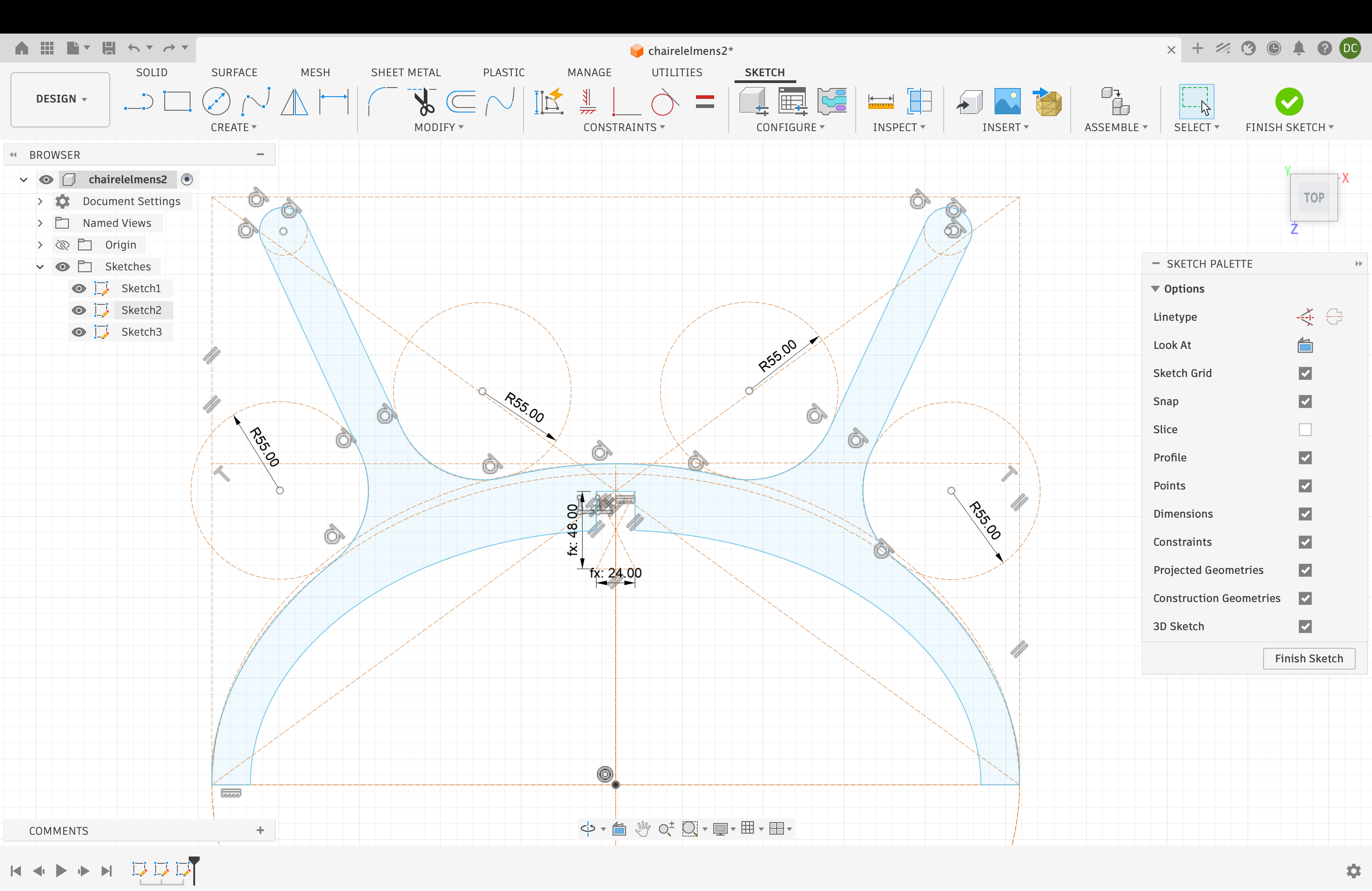
The last side sketch connected the seat to the legs.
This part gave the chair its main support.
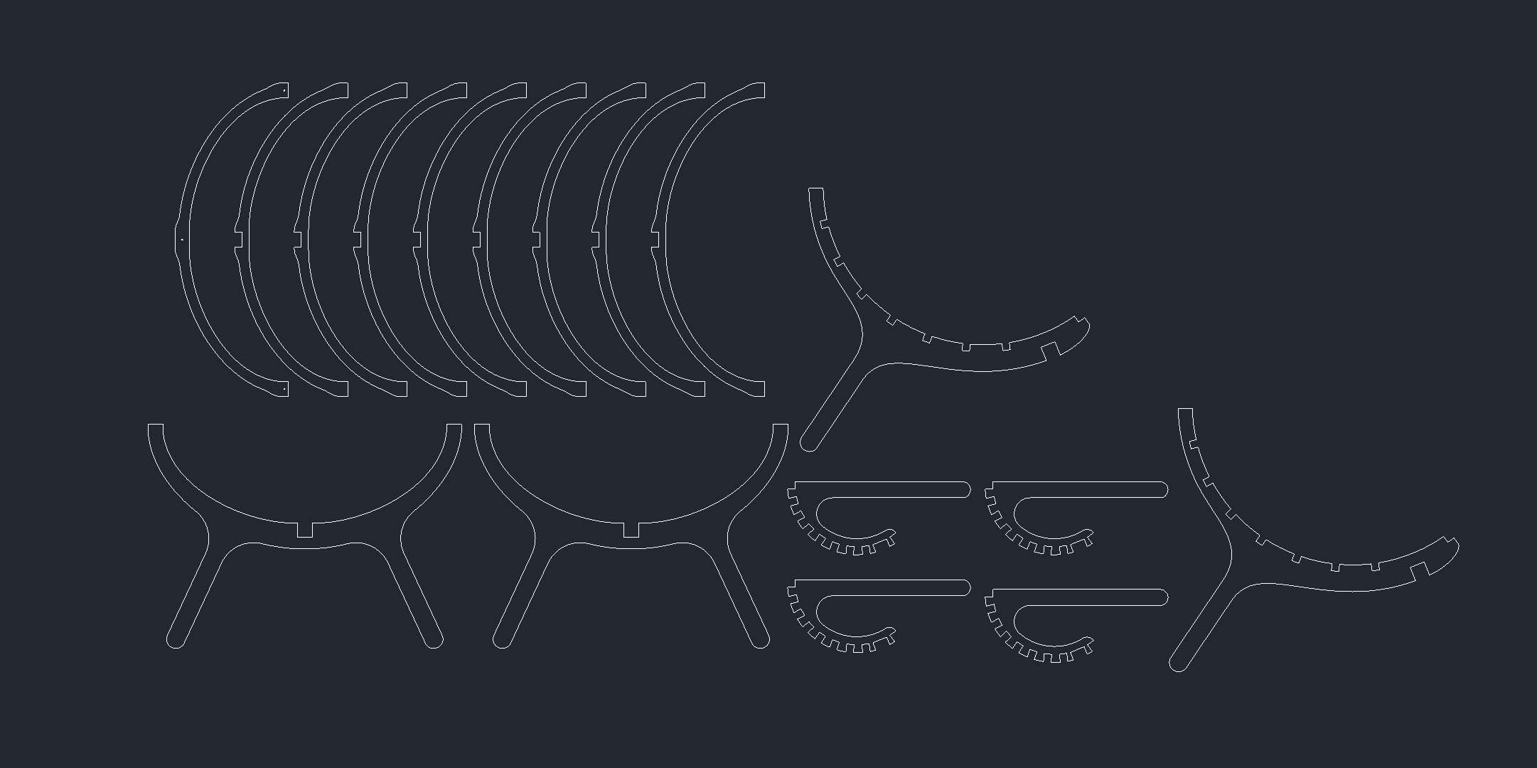
After the sketches were ready, I arranged all parts into a cutting layout.
The layout included ribs, side frames, arms, and connection slots.
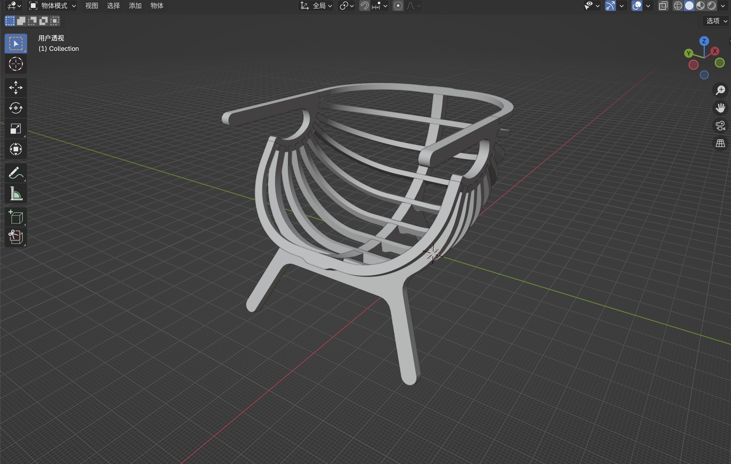
I checked the full chair in Blender before cutting.
This helped me see the whole shape in 3D.
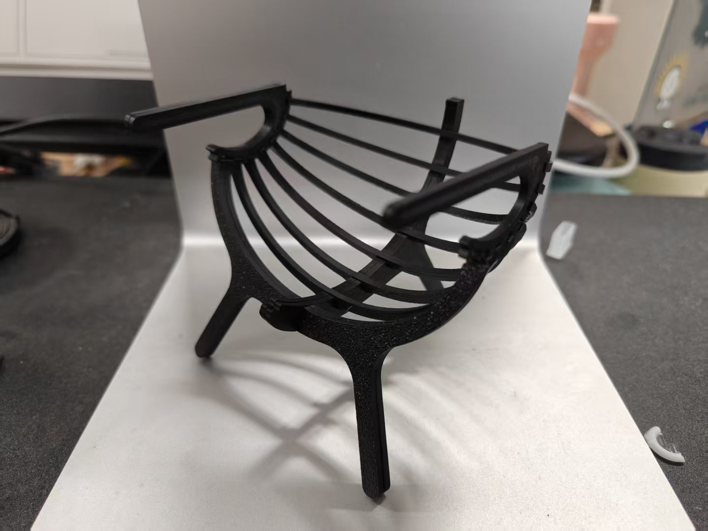
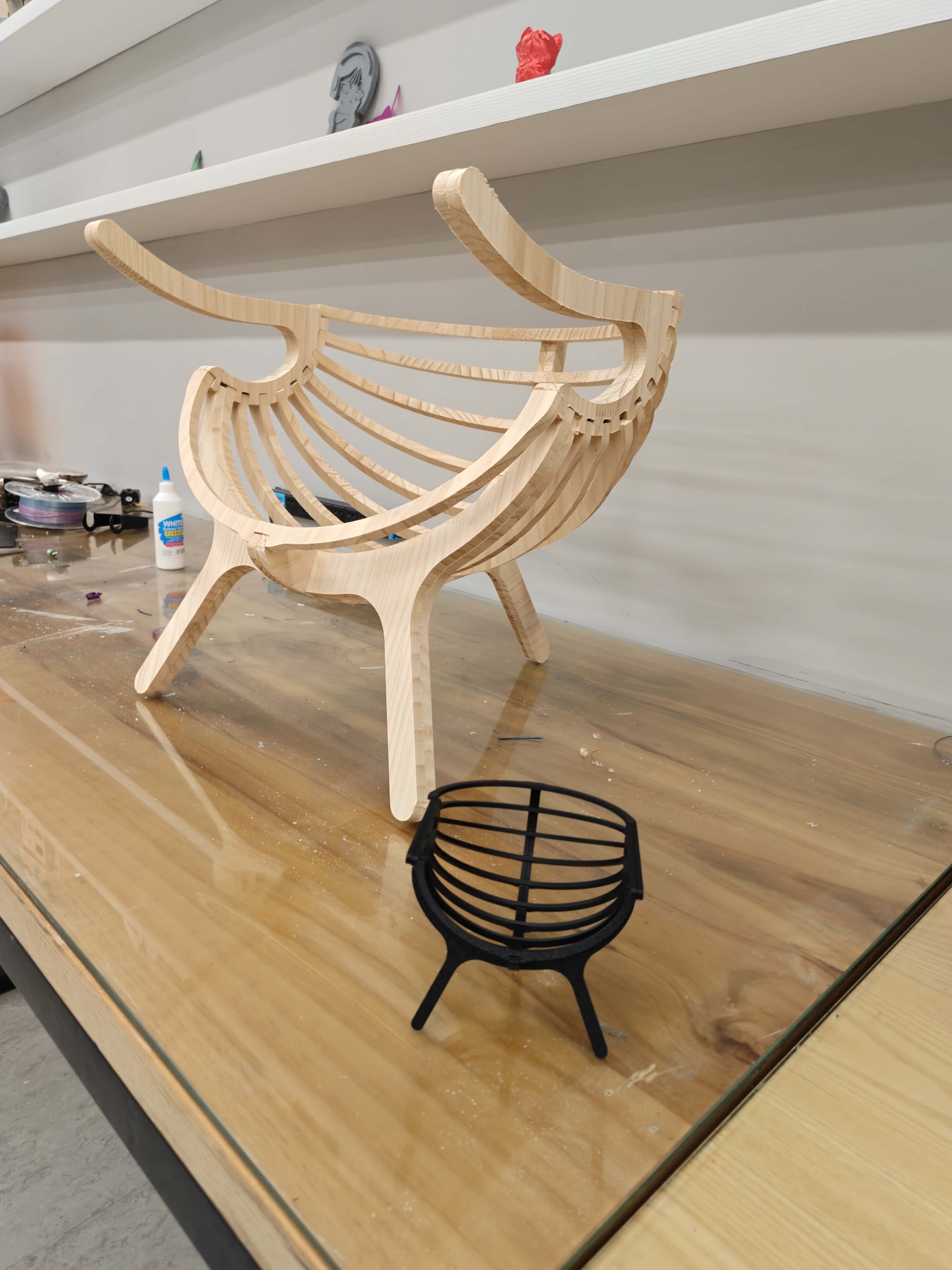
I also 3D printed a small sample.
The sample helped me check the form and assembly.
After that, I sent the layout to CNC cutting.
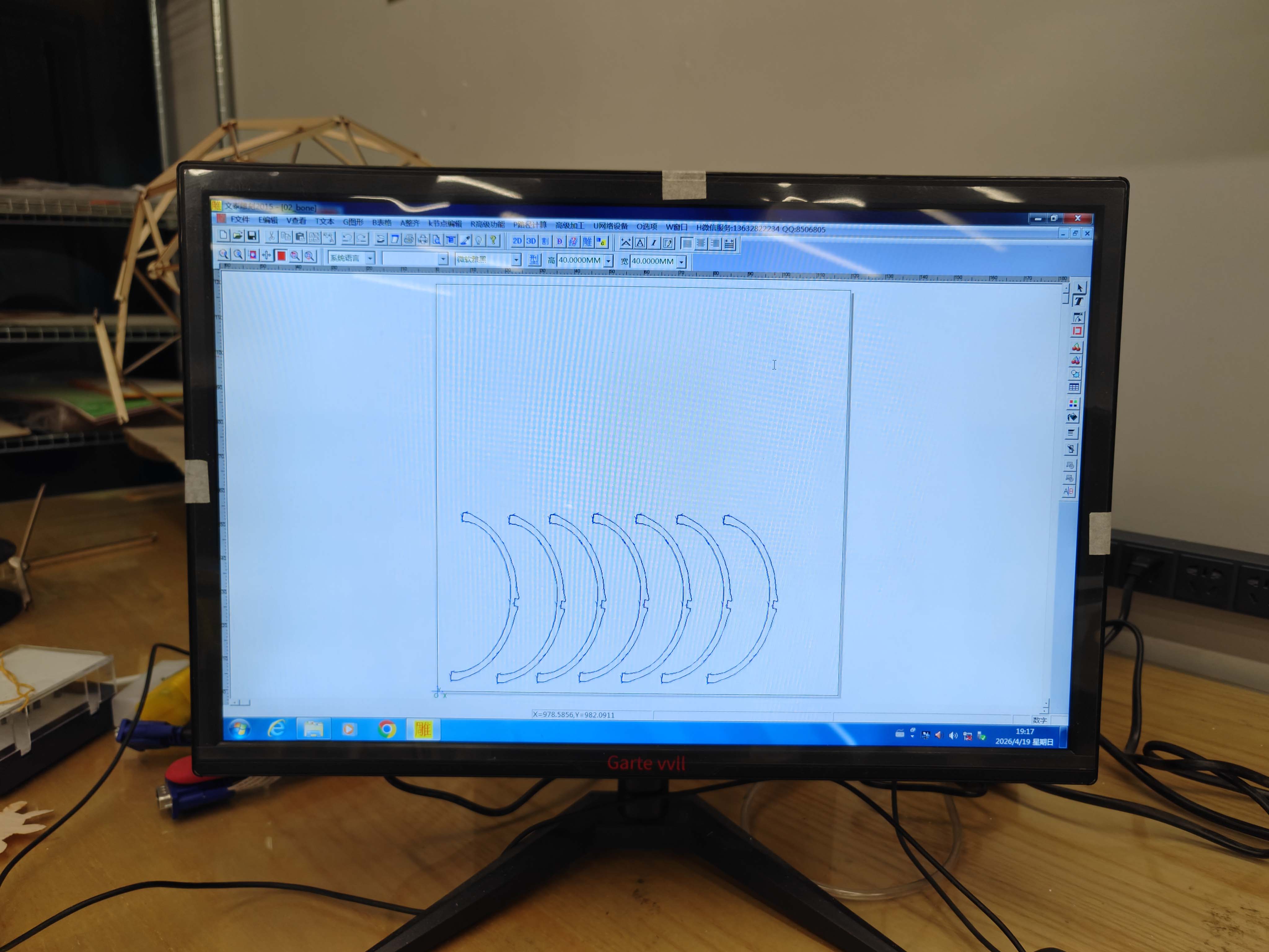
Toolpath design software
I exported the clean profiles as a DXF file.
Then I imported the file into the toolpath software.
I checked the outline of each part.
I also checked the cutting side of each toolpath.
This was important because the end mill has a real width.
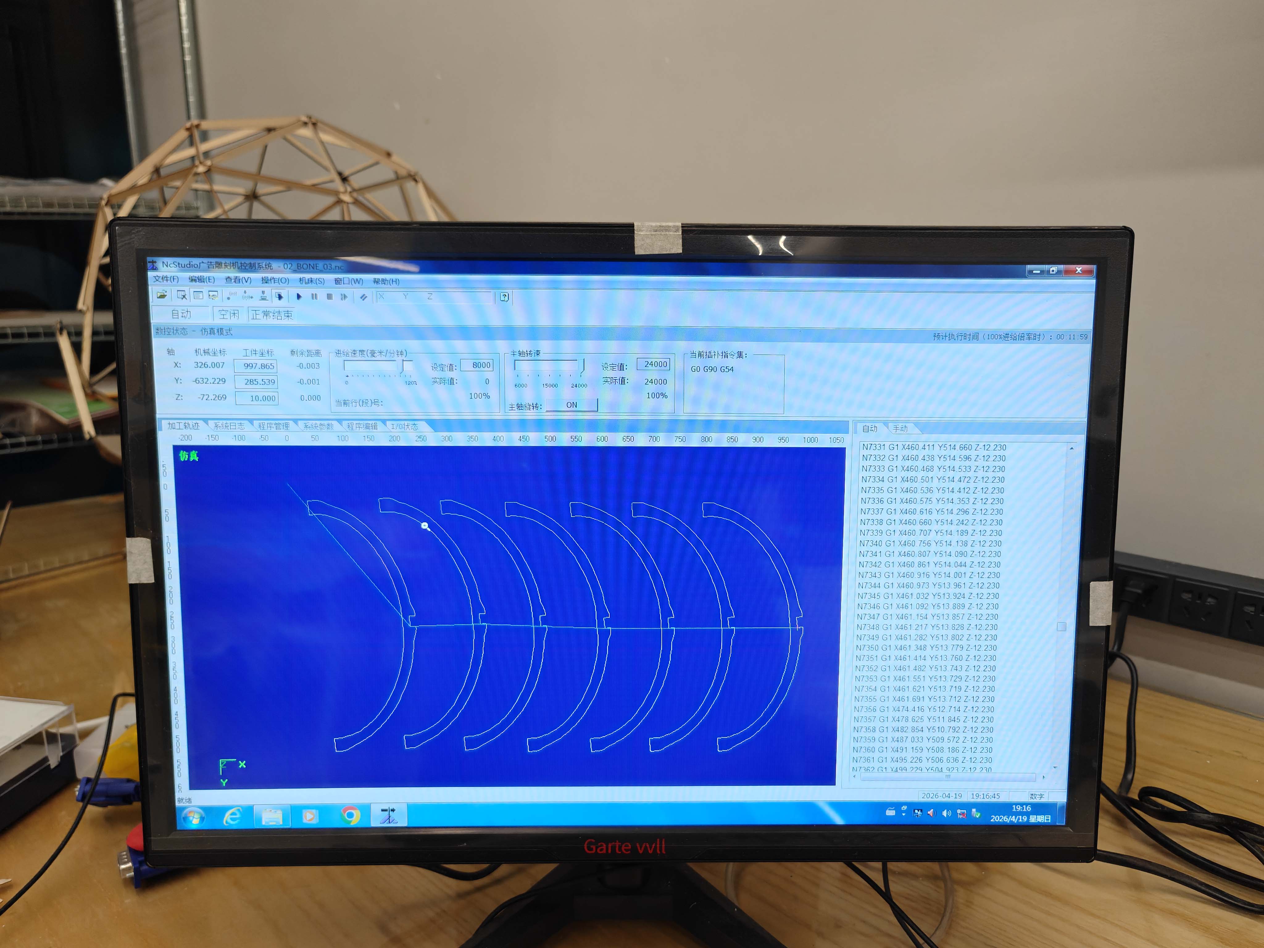
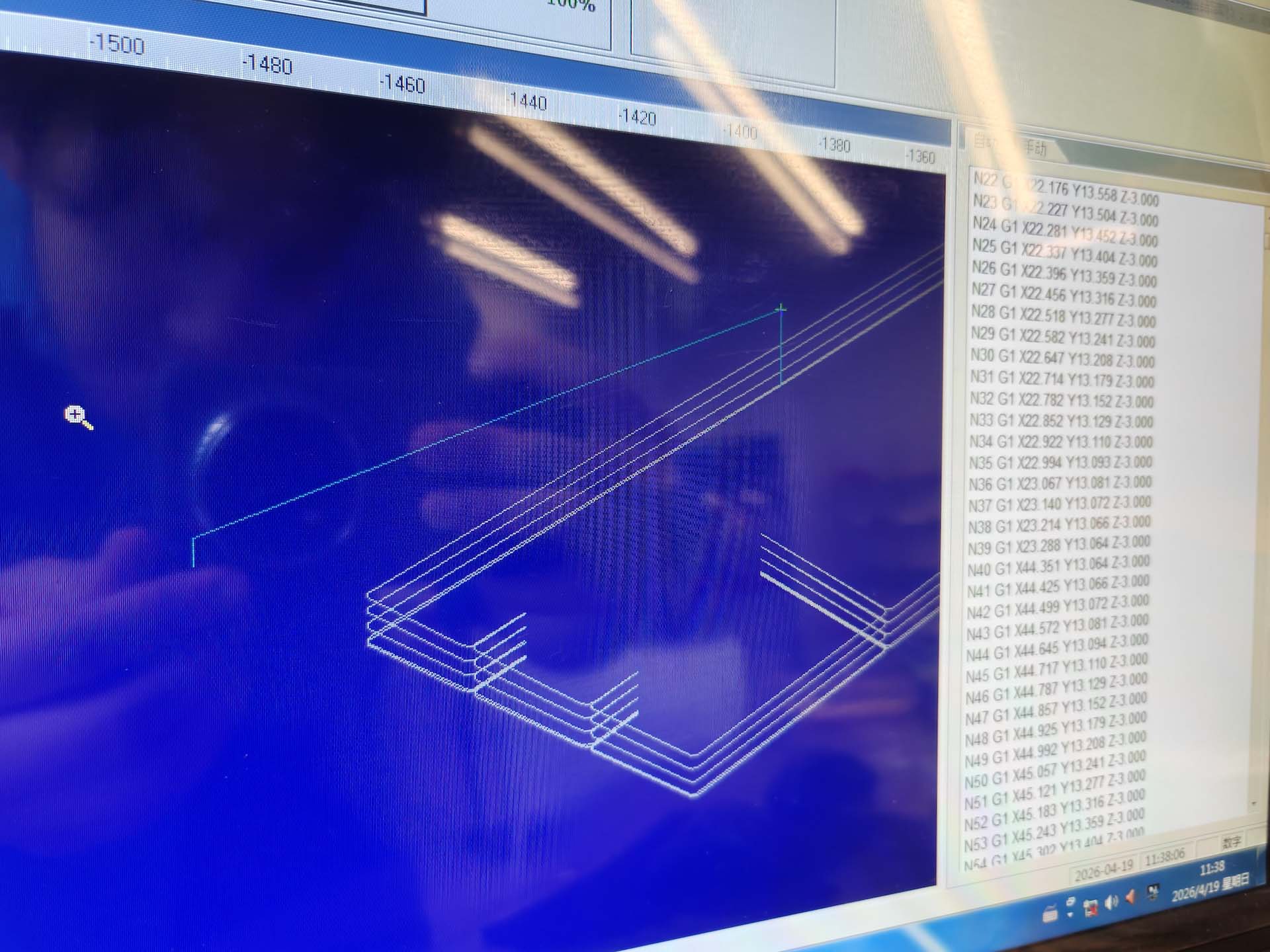
CNC working software
I opened the job in the CNC working software.
I checked the toolpath, coordinates, and generated code.
This was my last software check before cutting.
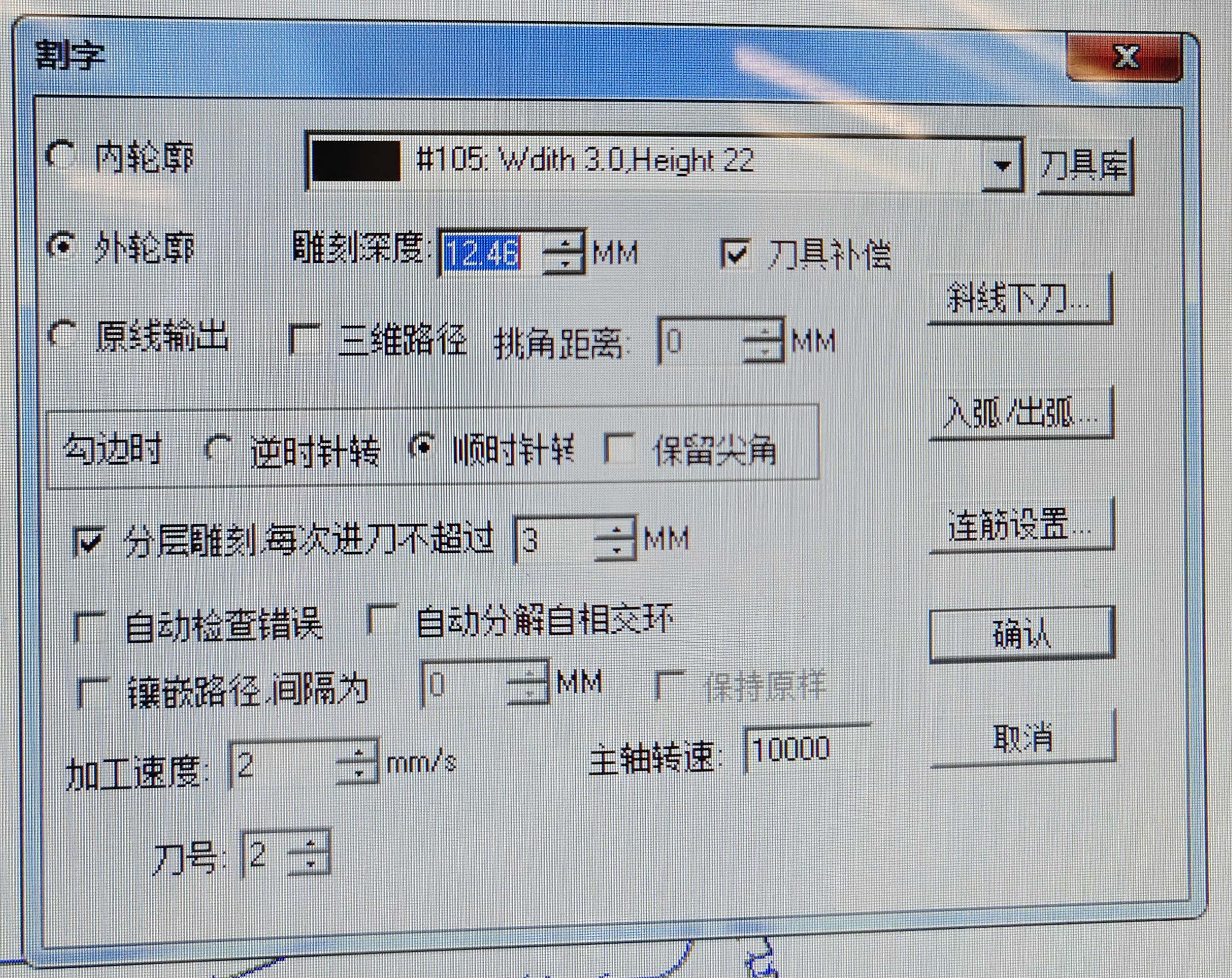
Cutting parameters
I set the cutting parameters before machining.
The visible tool width was 3.0 mm.
The material height was set to 22 mm.
The cutting depth was 12.46 mm.
The maximum step-down was 3 mm per pass.
The machining speed was 2 mm/s.
The spindle speed was 10000 RPM.
| Parameter | Value used | Purpose |
|---|---|---|
| Tool width | 3.0 mm | It defines the cutter diameter. |
| Material height | 22 mm | It sets the stock height. |
| Cutting depth | 12.46 mm | It sets the total cutting depth. |
| Step-down | 3 mm per pass | It limits each cutting layer. |
| Machining speed | 2 mm/s | It controls tool movement speed. |
| Spindle speed | 10000 RPM | It controls tool rotation speed. |
Machine and material setup
I placed the wooden sheet on the CNC bed.
I fixed the sheet before machining.
Good fixturing prevents movement during cutting.
I also checked the tool bit before starting.
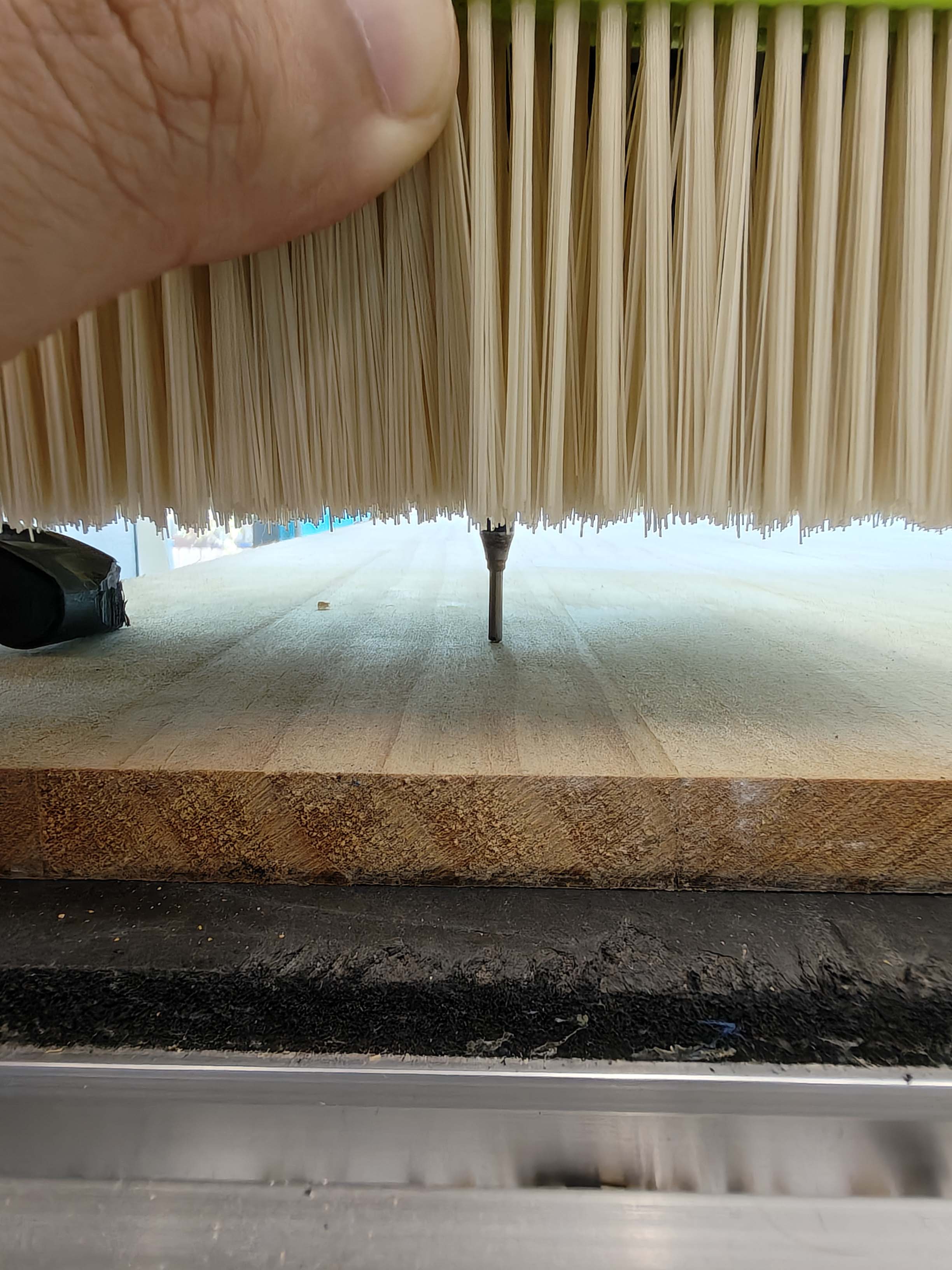
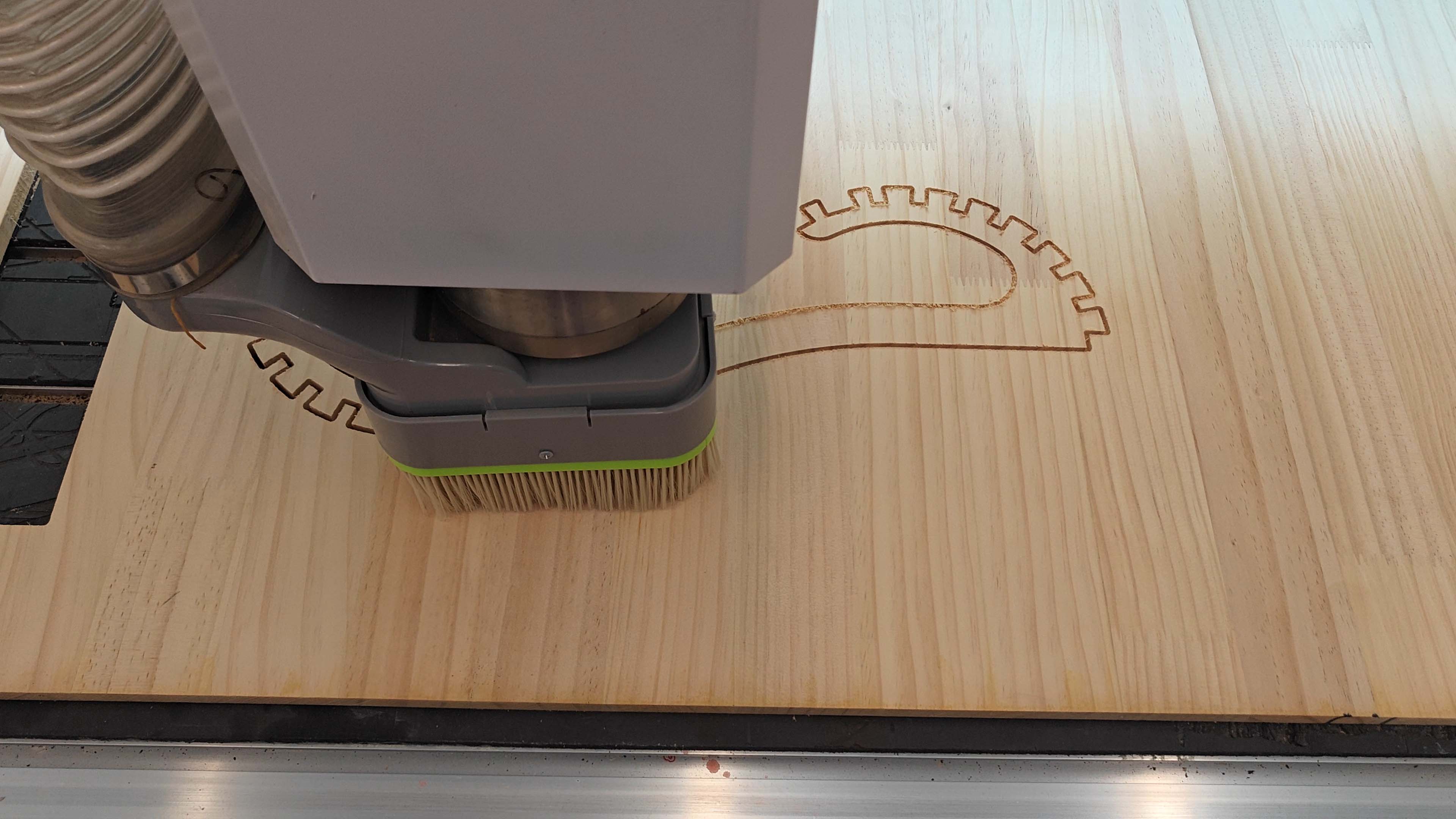
CNC milling process
The CNC router followed the generated toolpath.
It cut the chair parts from the wooden sheet.
I watched the cutting process carefully.
I checked the sound, dust collection, and cut quality.
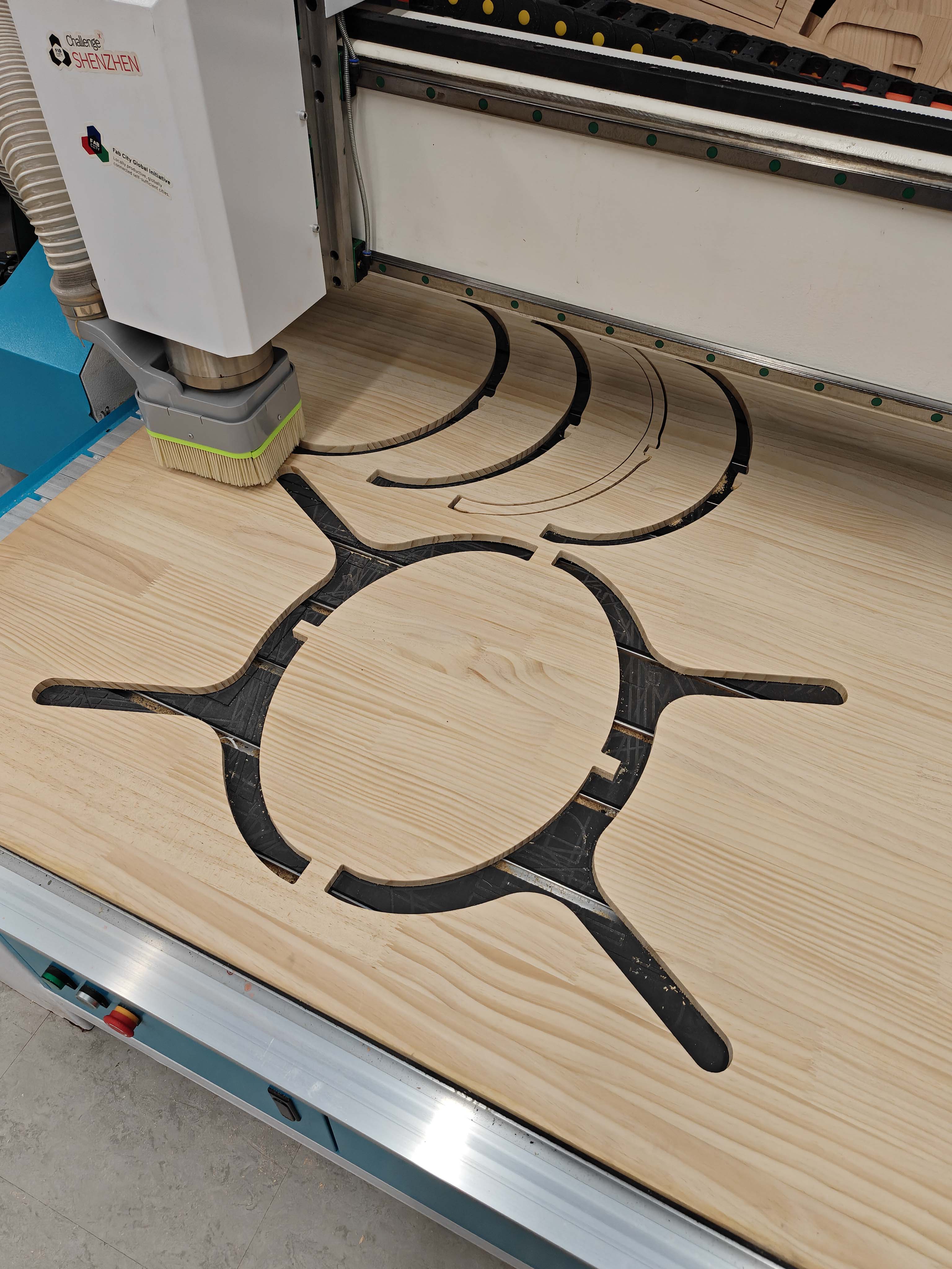
CNC milling result
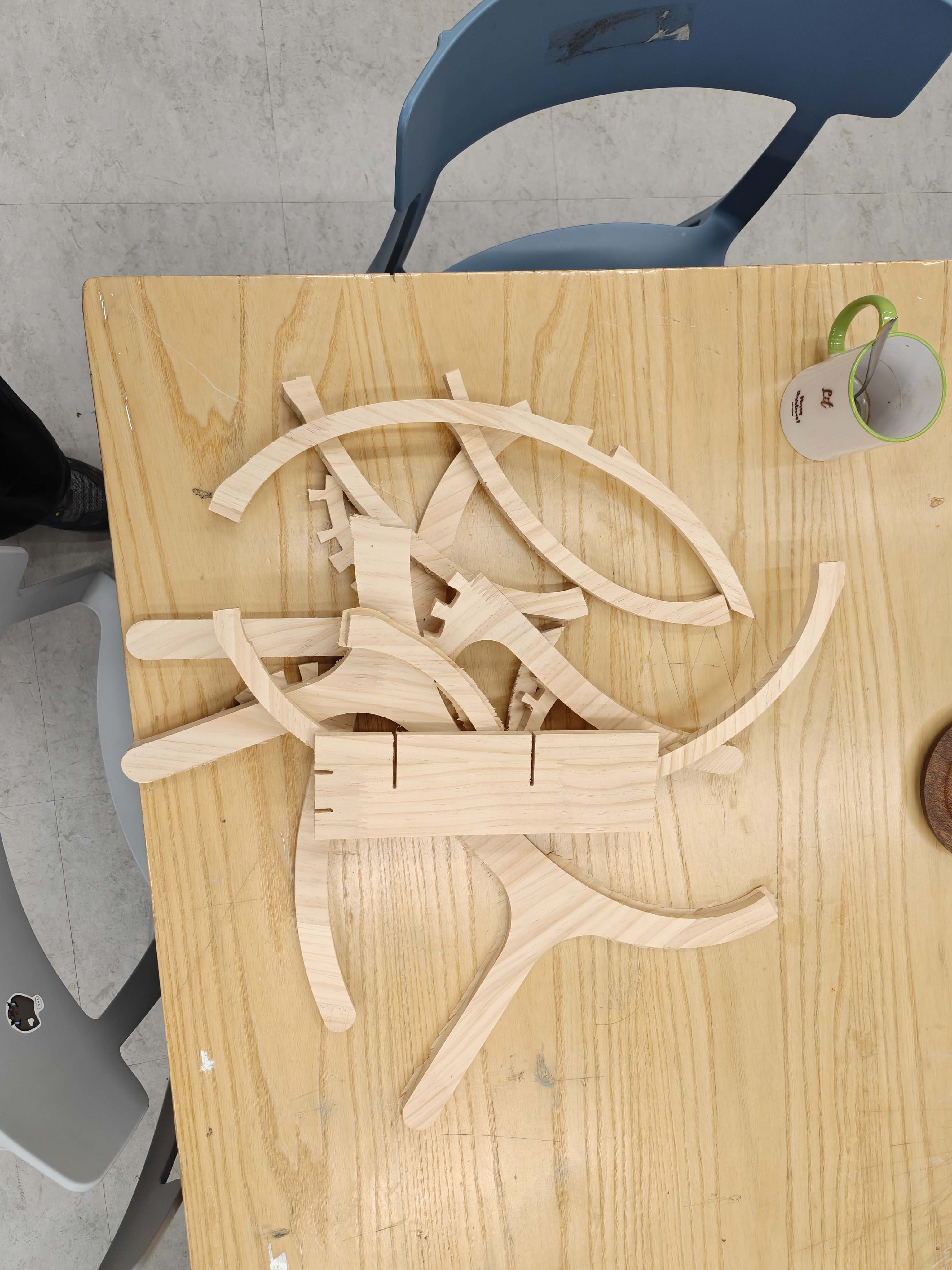
After cutting, the parts were still inside the wooden sheet.
I checked the ribs, side frames, and slot details.
I made sure the main profiles were complete.
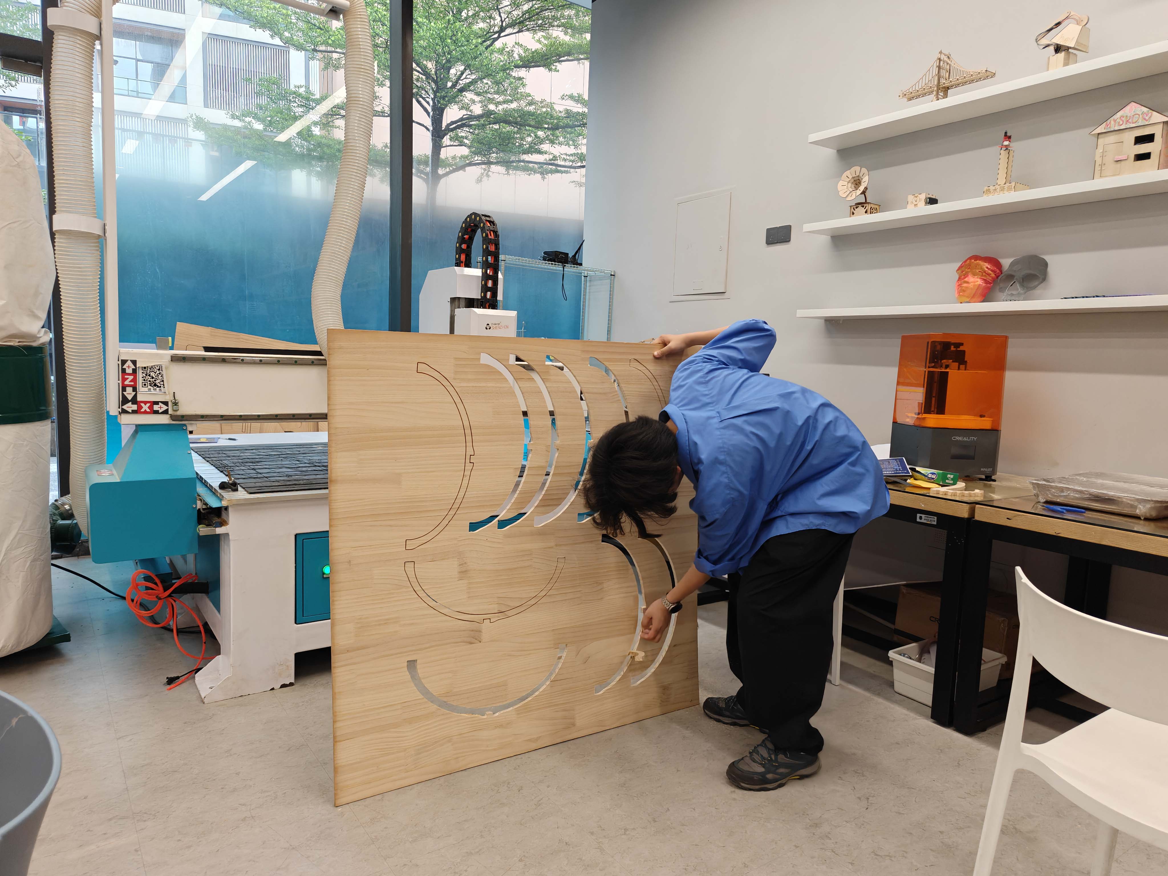
Removing the parts
I removed the parts from the wooden sheet.
I did this carefully because the ribs were long and curved.
Then I checked the slots and edges.
Assembly
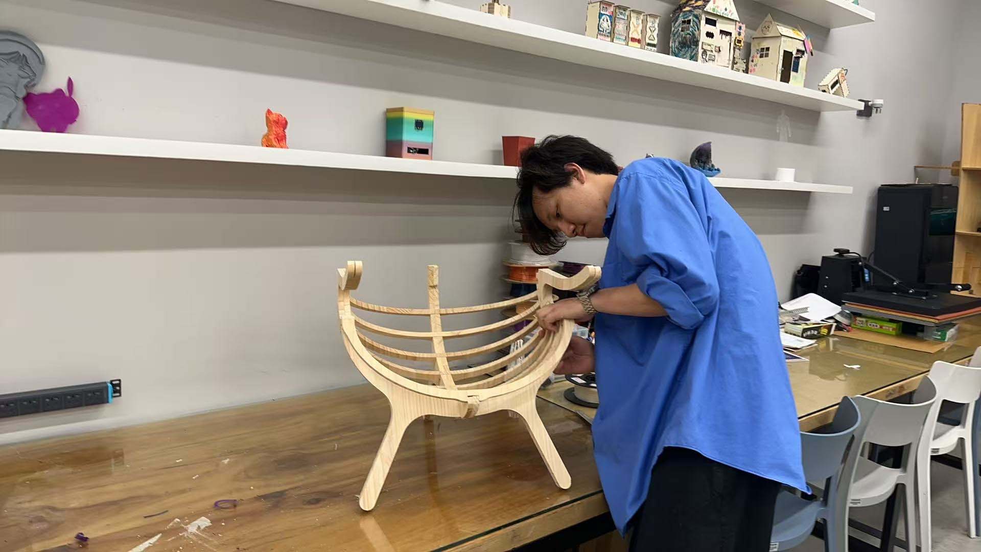
I assembled the chair from CNC-cut wooden parts.
The ribs were inserted into the side frames.
The slot fit was the most important part.
Tight slots made assembly difficult.
Loose slots made the structure unstable.
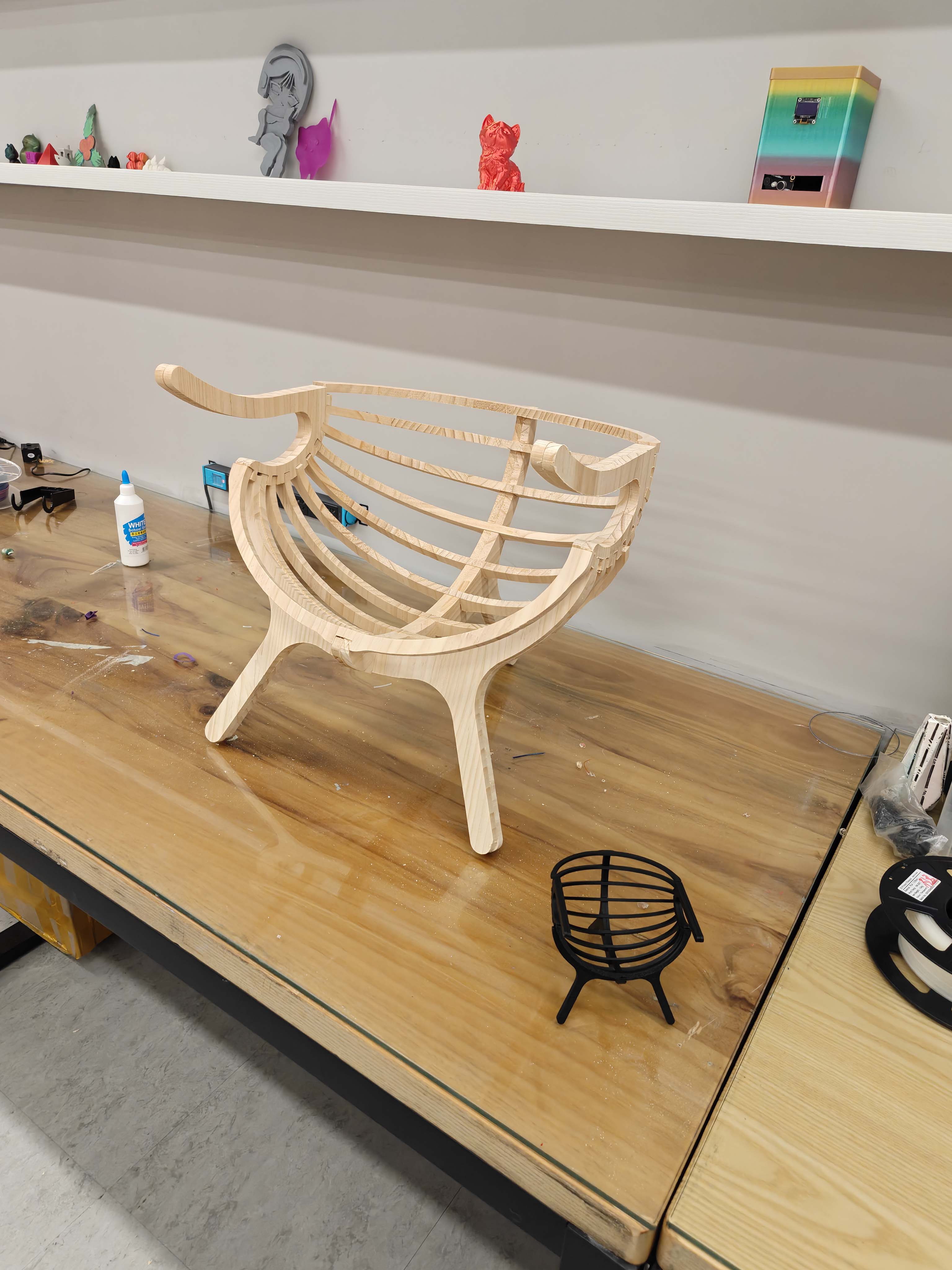
Final result
The final chair was made from CNC-cut wooden sheet material.
Flat parts formed a curved shell-like structure.
The design still needs better edge finishing.
The slot tolerance also needs more testing.
Problems and Solutions
| Problem | Reason | Solution |
|---|---|---|
| The first DXF had too many points. | Fusion 360 became slow and hard to edit. | I rebuilt the main curves with cleaner sketches. |
| The board thickness affected every slot. | The real material thickness was 12 mm. | I used slot_w and slot_l as 12 mm parameters. |
| The curved parts were hard to understand. | Flat profiles had to become a 3D chair. | I checked the full assembly in Blender. |
| The assembly was risky before CNC cutting. | A large CNC mistake wastes material and time. | I 3D printed a small sample first. |
| The slots needed a better fit. | Tight slots were hard to assemble. | I checked the fit during sample assembly. |
AI Use Statement
I used AI to help organize my documentation text.
I used it to make the sentences shorter and clearer.
I also used it to check the English wording and page structure.
The design, modeling, machining, testing, photos, and final decisions were my own work.
Design Files
I exported four DXF files for the main chair parts.