Overview
Computer-aided design connects visual ideas with fabrication-ready models. This week I explored three different design approaches: raster image editing, vector drawing, and parametric 3D modeling.
Raster design in Photoshop is useful for visual editing and image processing. Vector design in Illustrator uses mathematical paths, which are more suitable for precise 2D fabrication. Parametric modeling in Fusion 360 uses dimensions and constraints to control editable 3D geometry.
The goal was to understand how different digital representations affect later fabrication workflows, file formats, and documentation quality.
Assignment Requirements
The assignment was to model experimental objects using 2D and 3D design tools, compress images and videos, and document the process with design files on the class page.
- 2D raster design: Photoshop
- 2D vector design: Illustrator
- 3D parametric modeling: Fusion 360
- Image compression: Photoshop Image Processor
- Video compression: Jianying / CapCut
- Original design files included for download
2D Design Workflows
The 2D part of this week focused on comparing raster and vector workflows. This helped me understand the difference between pixel-based visual editing and geometry-based fabrication drawing.
Raster Workflow — Photoshop
Photoshop was used to explore raster image editing. Since raster images are made of pixels, they are useful for visual composition but less suitable for precise fabrication geometry.
Resolution Settings (DPI)
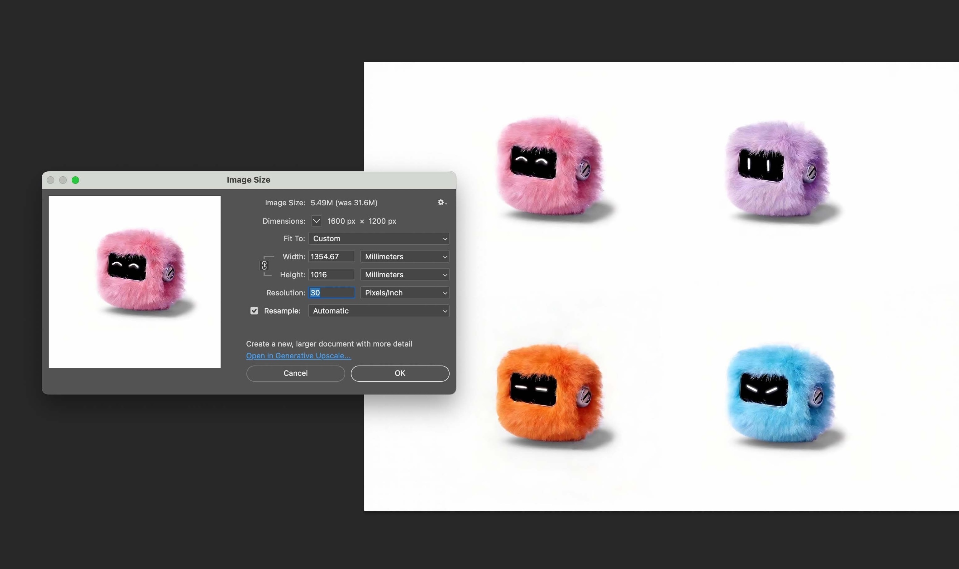
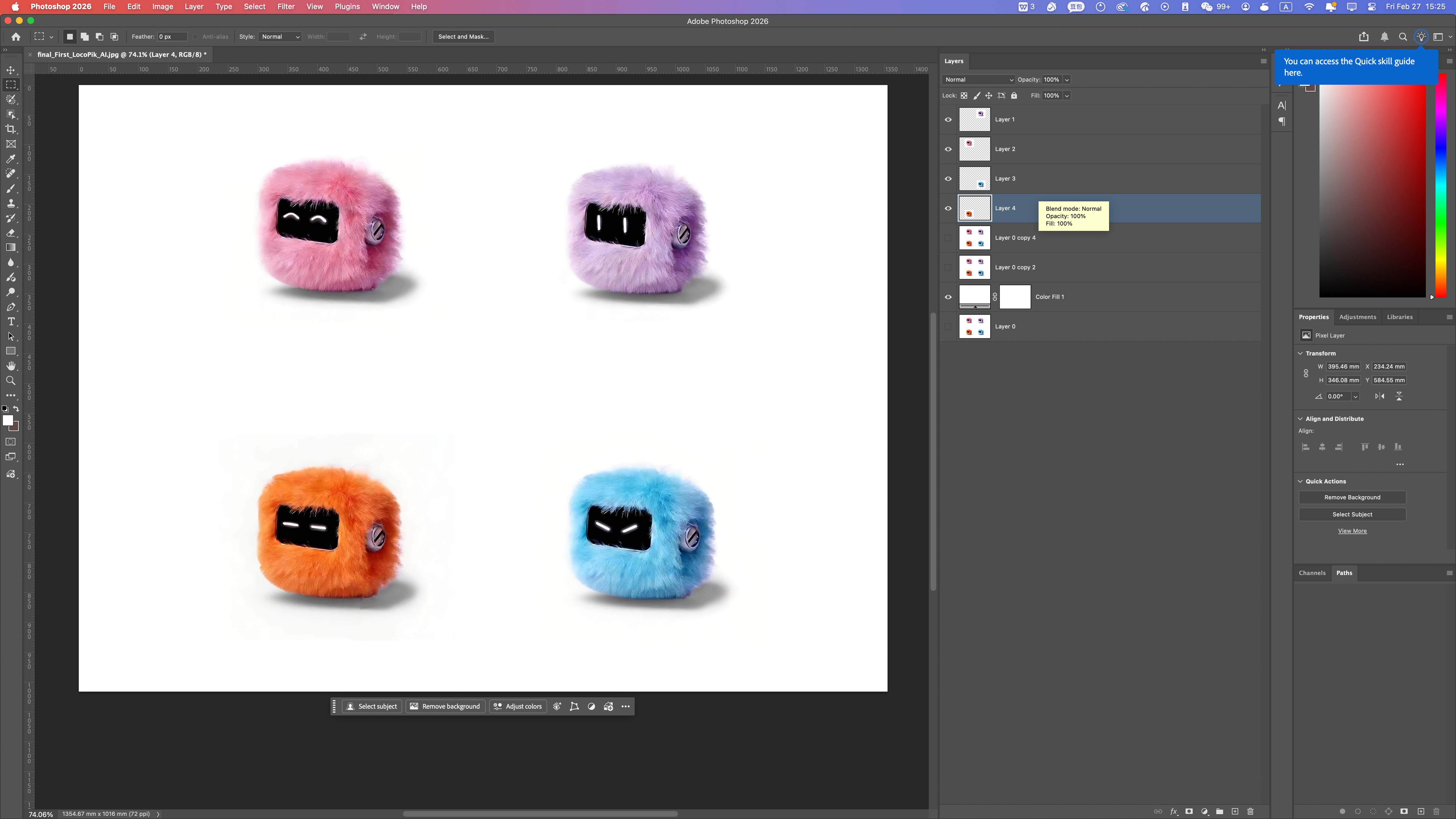
Layer Management
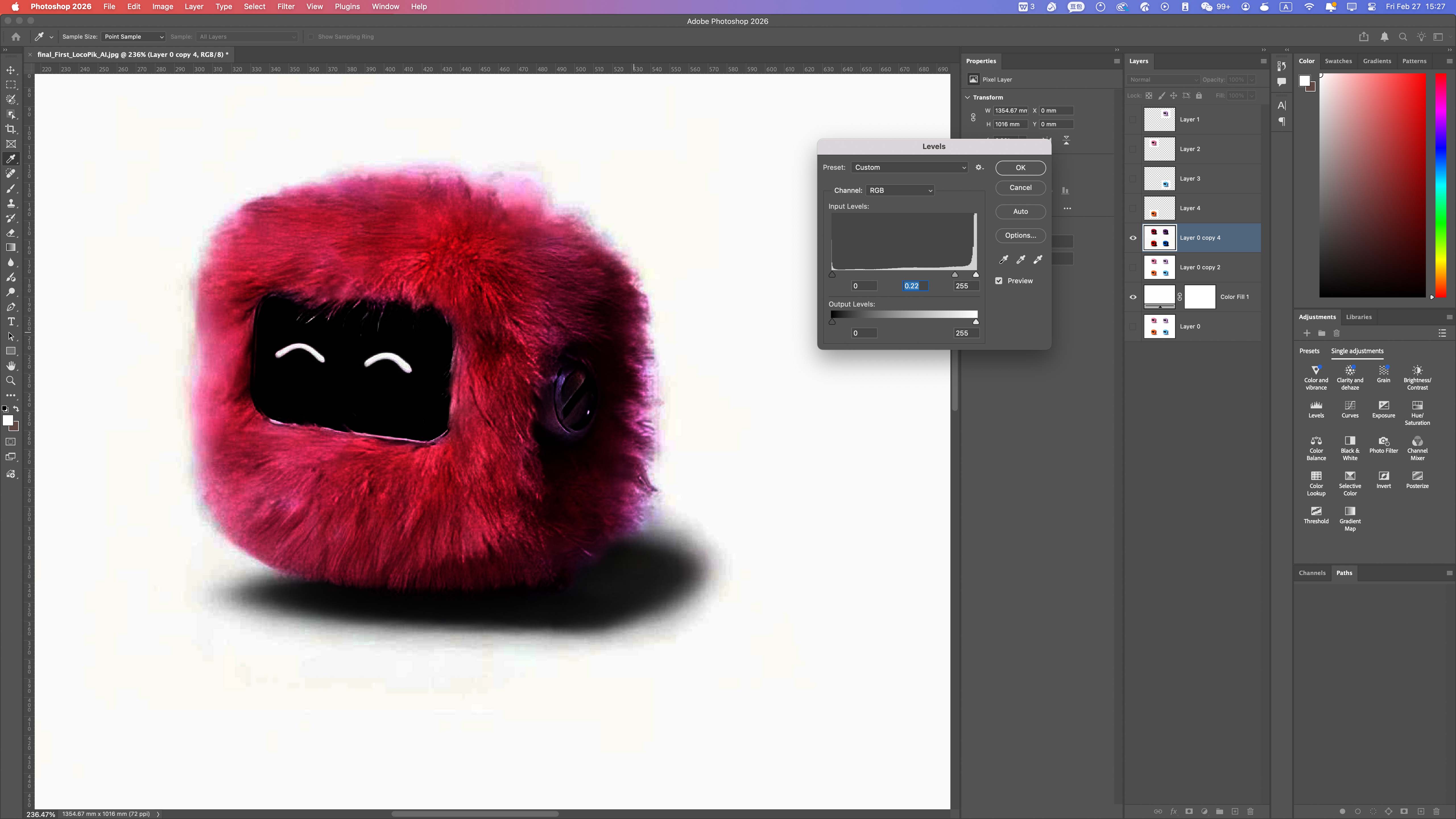
Basic Image Adjustments
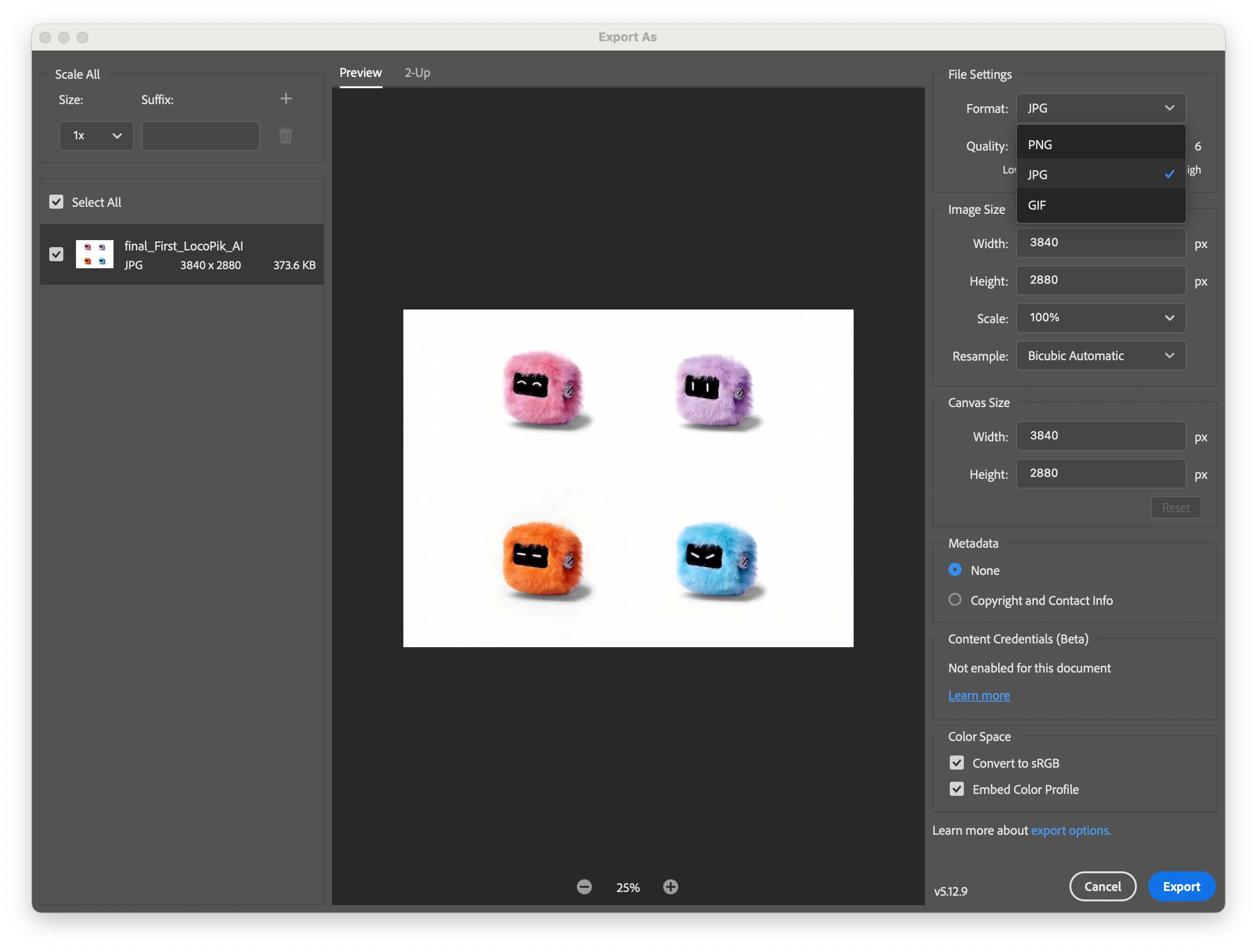
Exporting PNG and JPG
This workflow showed that raster images are effective for presentation and documentation, but they do not provide the clean geometric data required for digital fabrication.
Vector Workflow — Illustrator
Illustrator was used to explore vector drawing through paths, shape construction, boolean operations, and outline checking.
Building Base Geometry
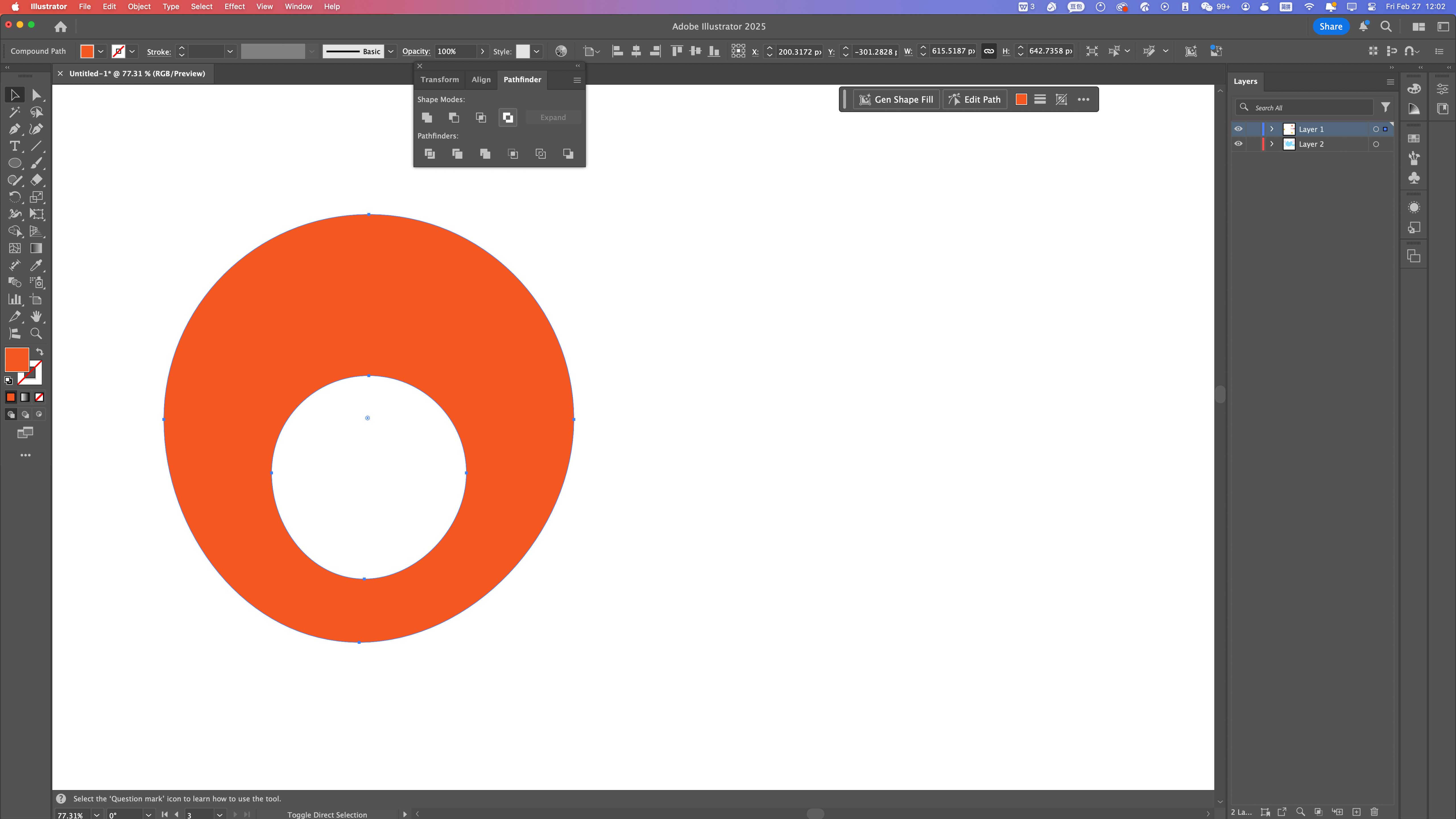
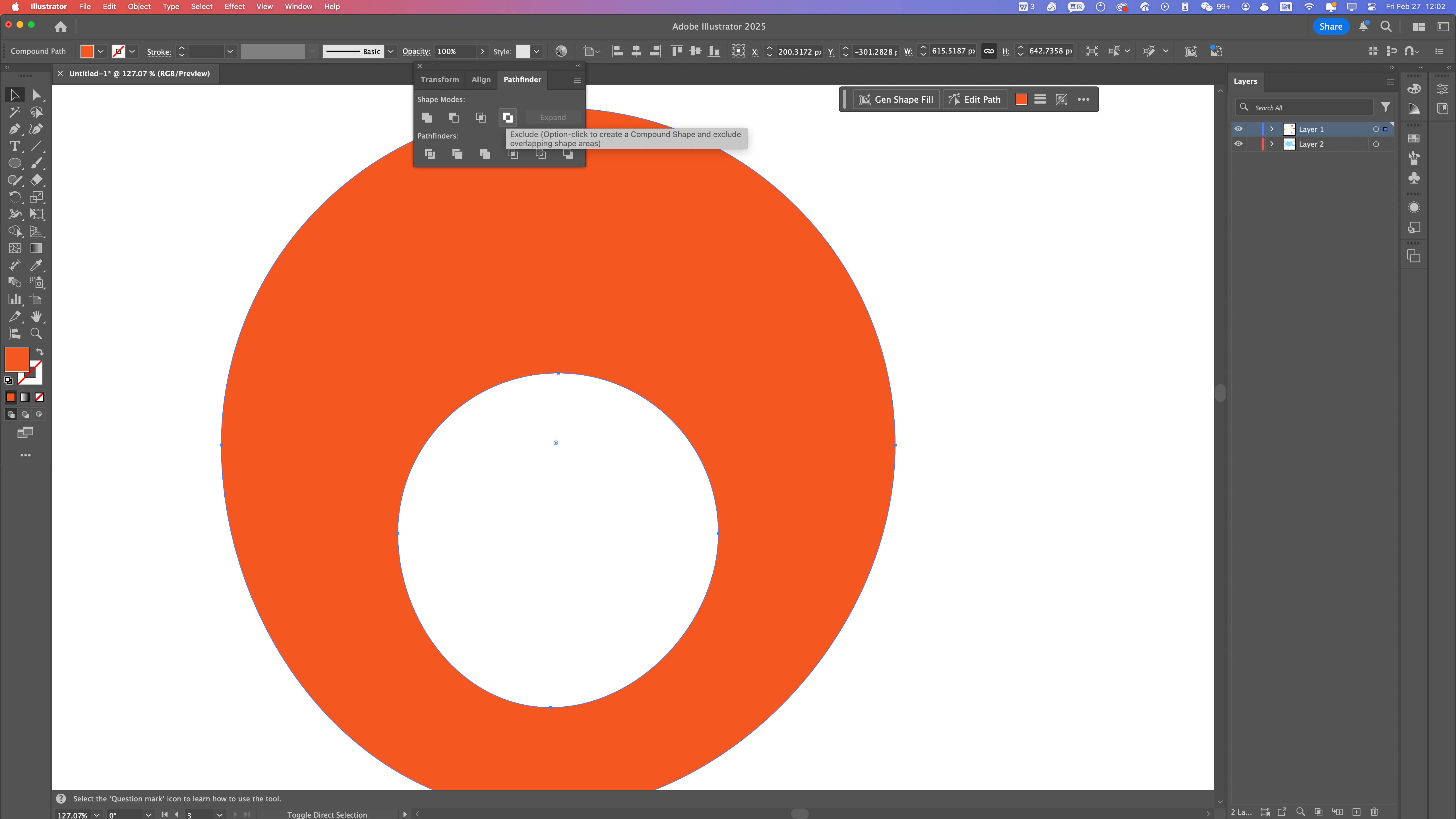
Boolean Operations (Pathfinder)
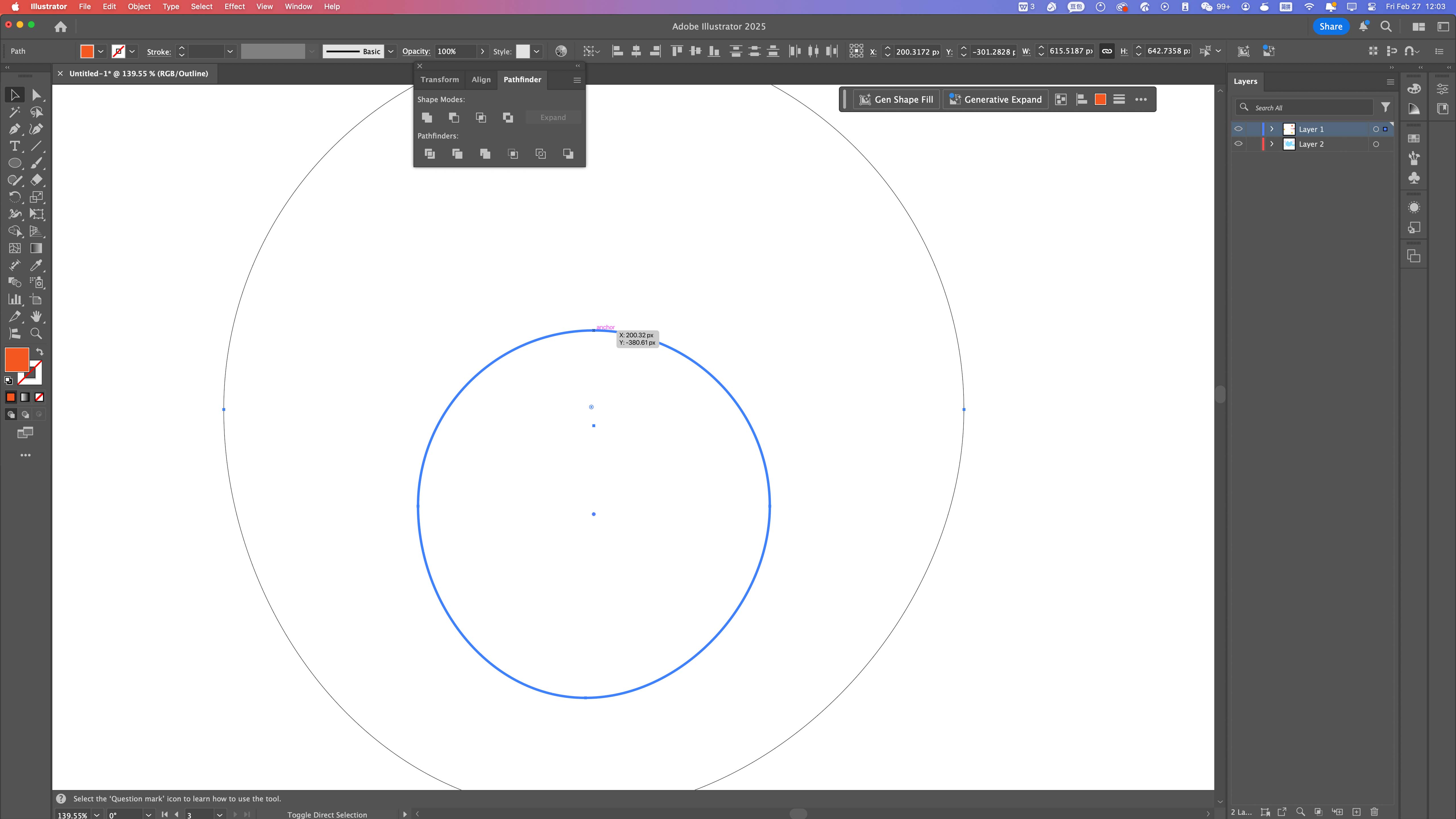
Outline Mode Verification
Final Composition
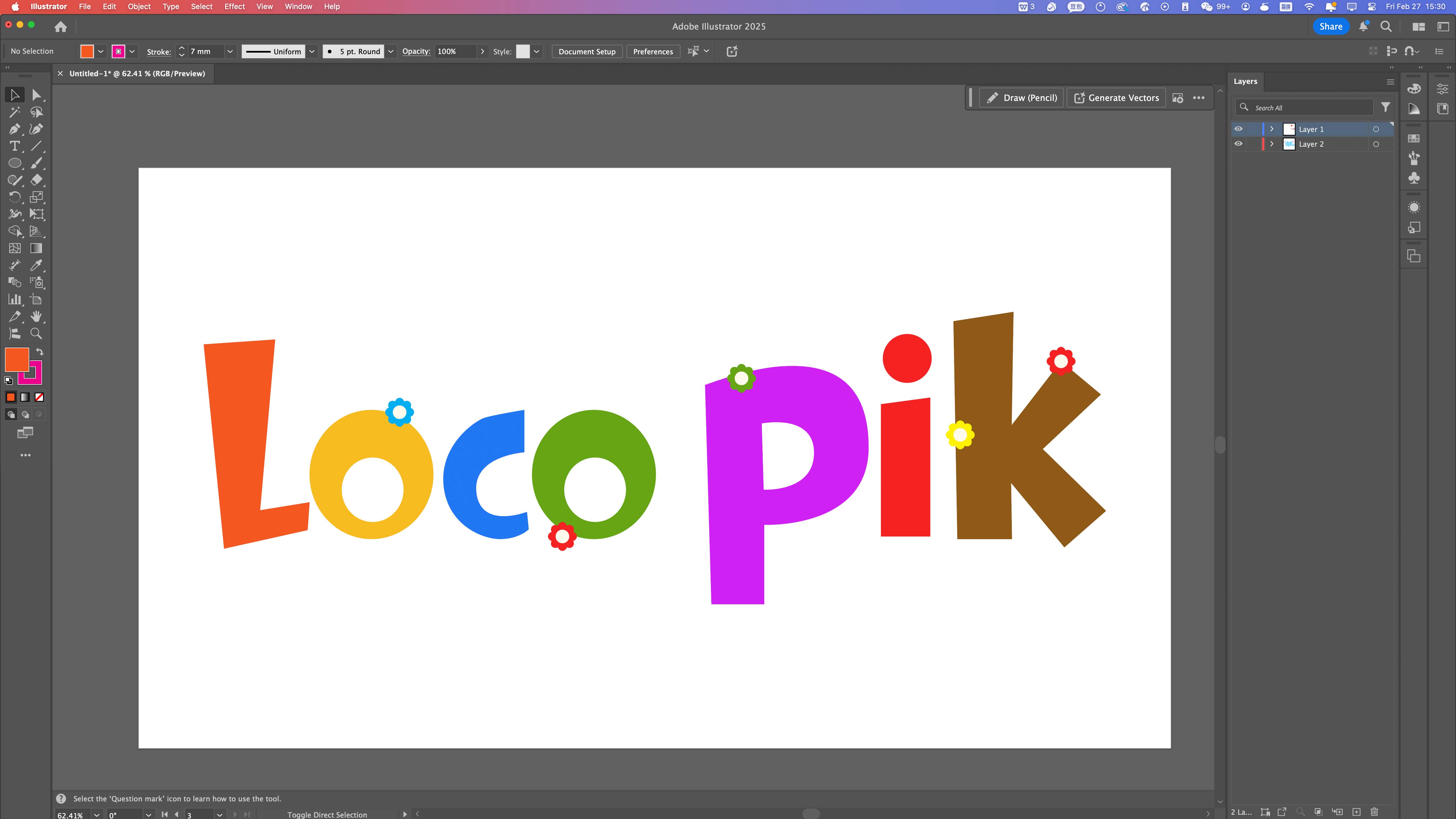
Vector graphics are defined by mathematical paths instead of pixels. This makes them suitable for fabrication processes such as laser cutting, where closed paths and clean geometry are essential.
3D Parametric Modeling
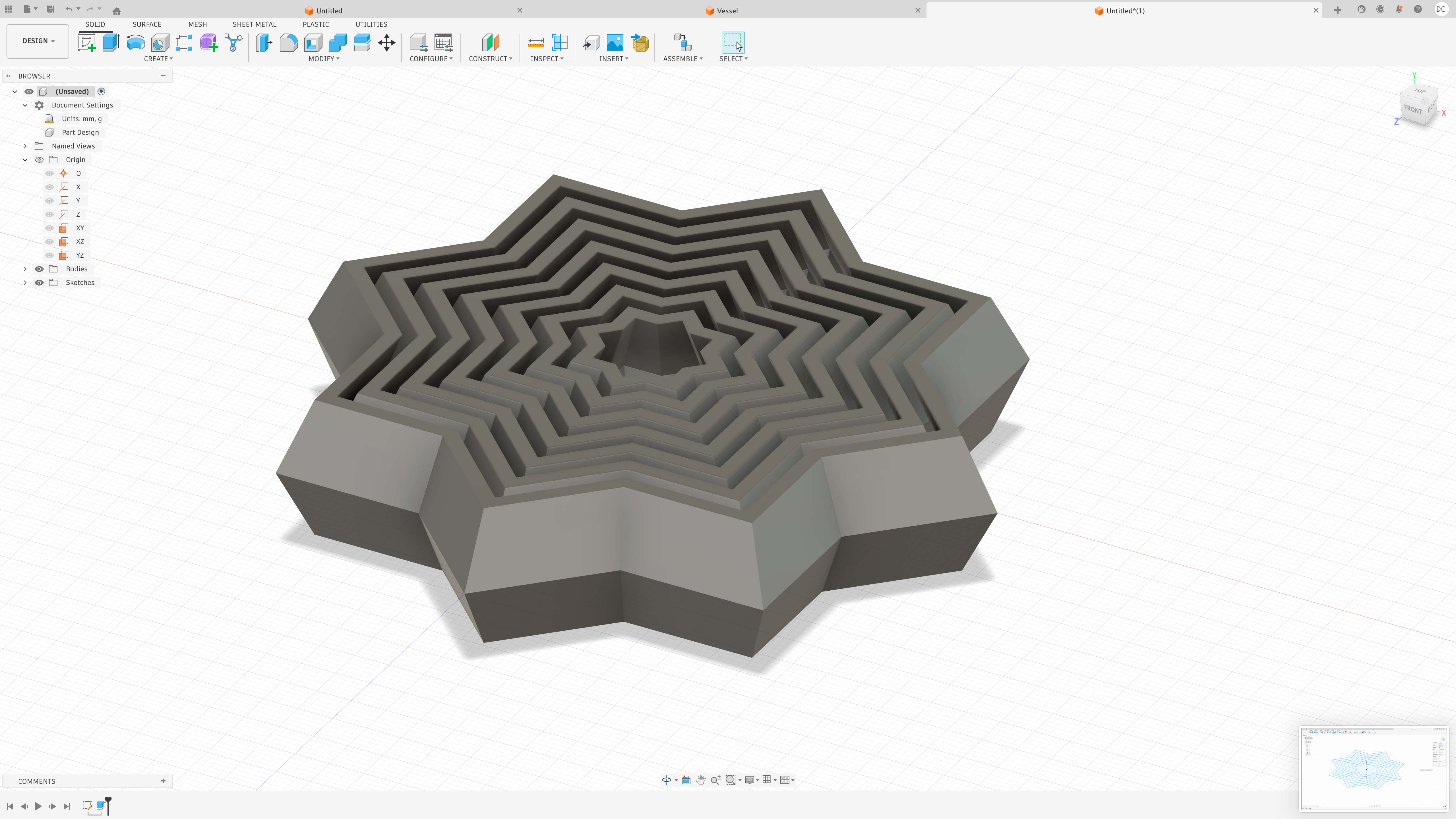
For 3D design, I used Fusion 360 to explore parametric modeling. This workflow is based on sketches, constraints, dimensions, and editable feature history.
Fusion 360 Workflow
I developed a layered radial form by constructing a constrained sketch, generating nested profiles, and extruding selected regions into a 3D structure.
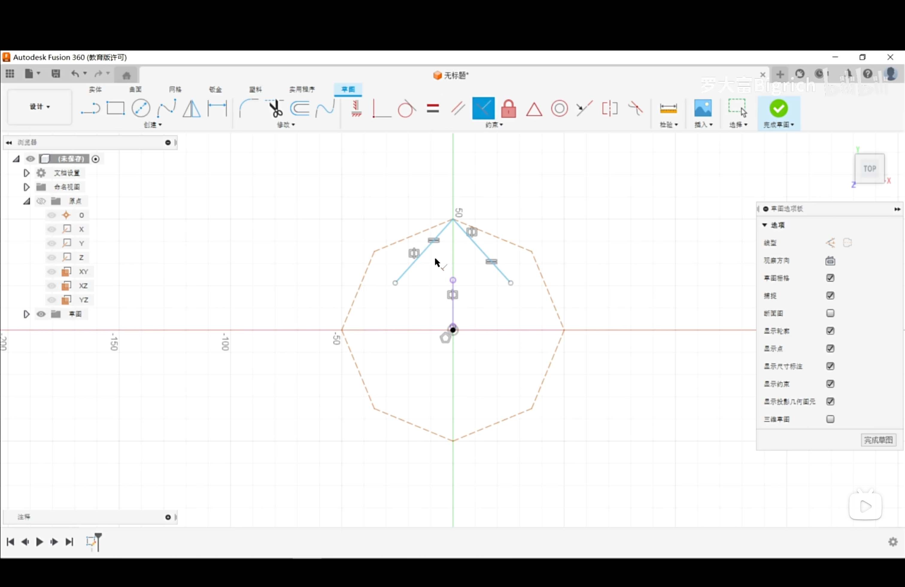
Step 1 — Polygon Construction
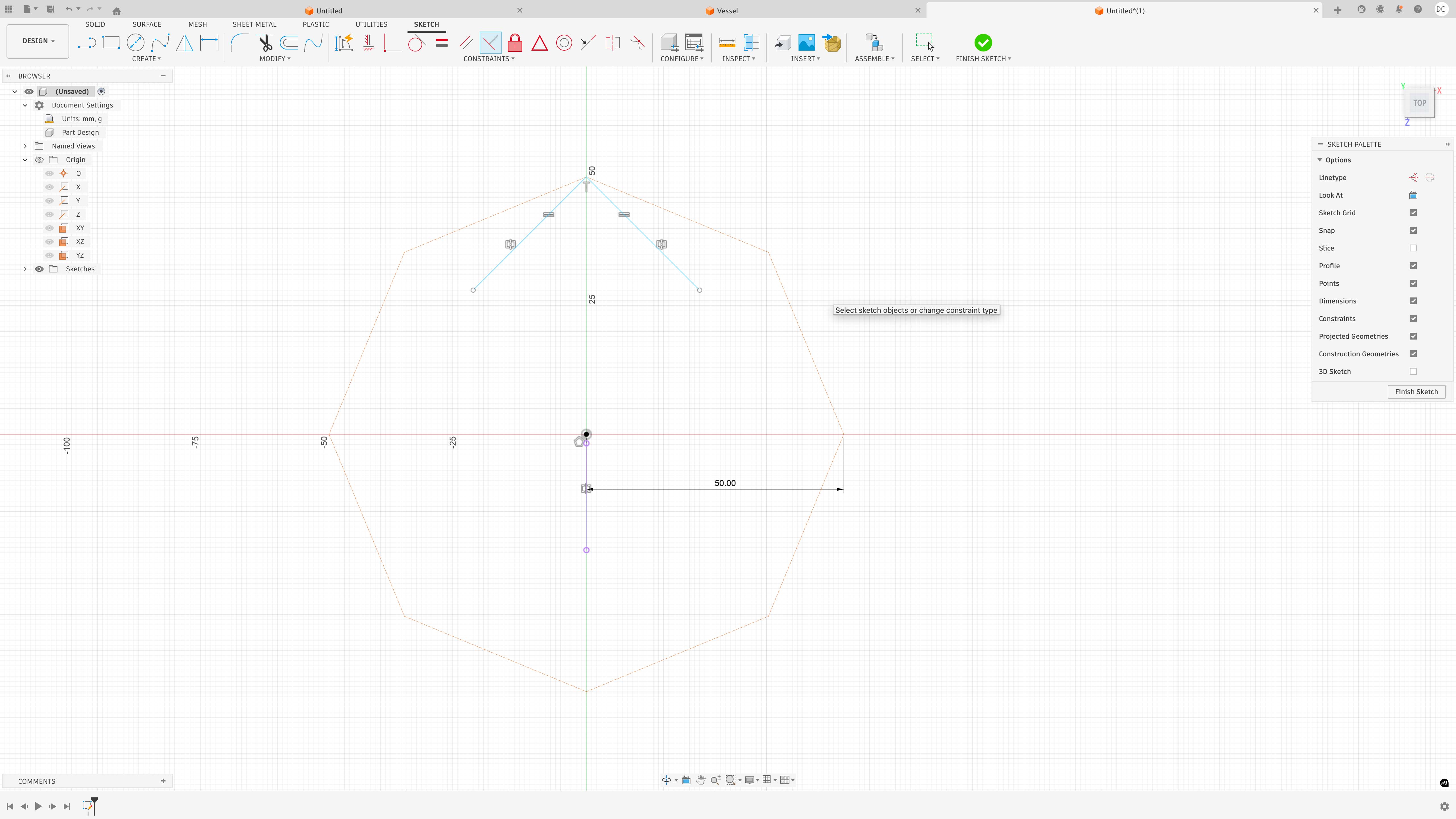
Step 2 — Fully Constrained Sketch
Step 3 — Offset Profiles
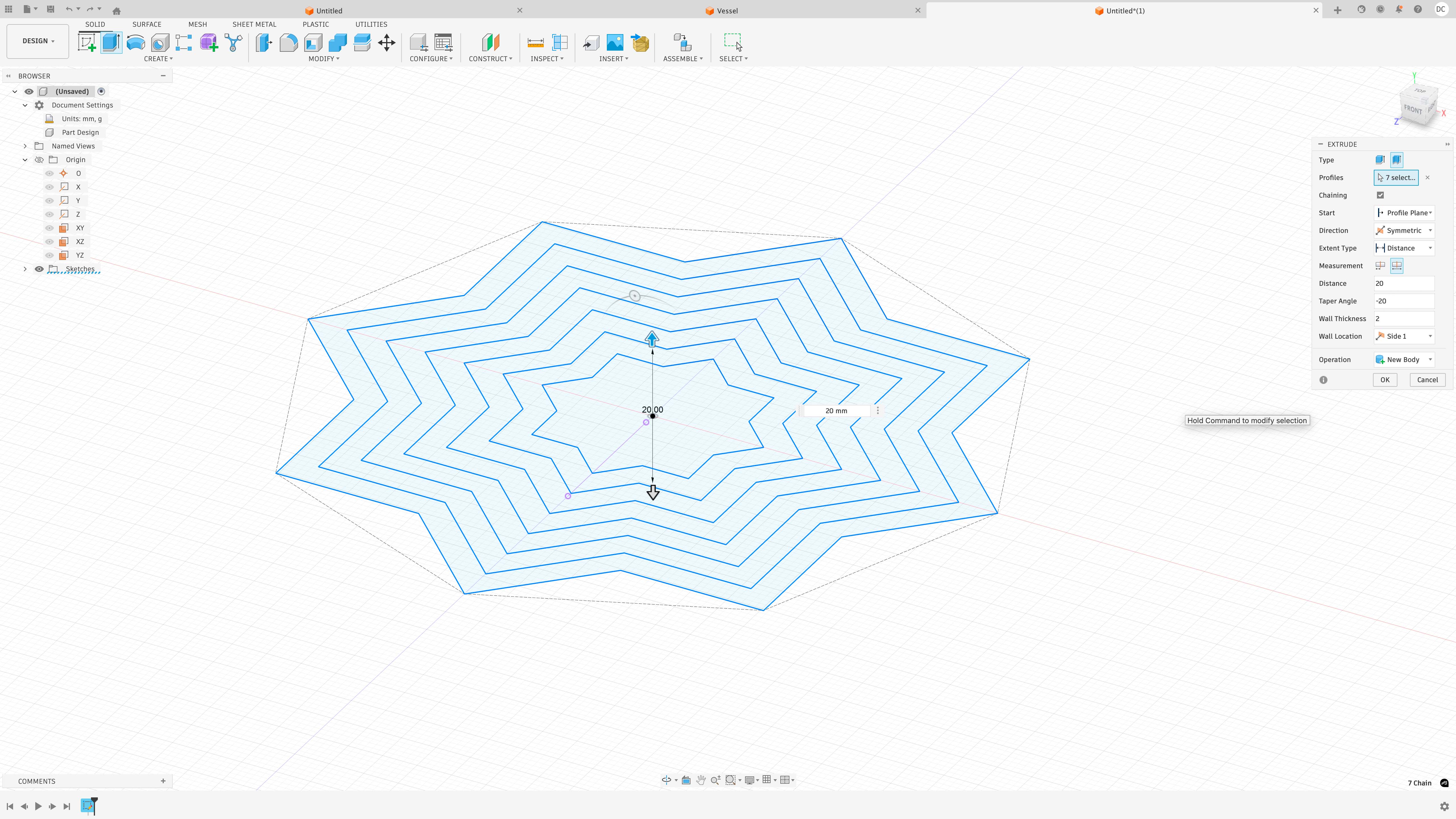
Step 4 — Extrusion
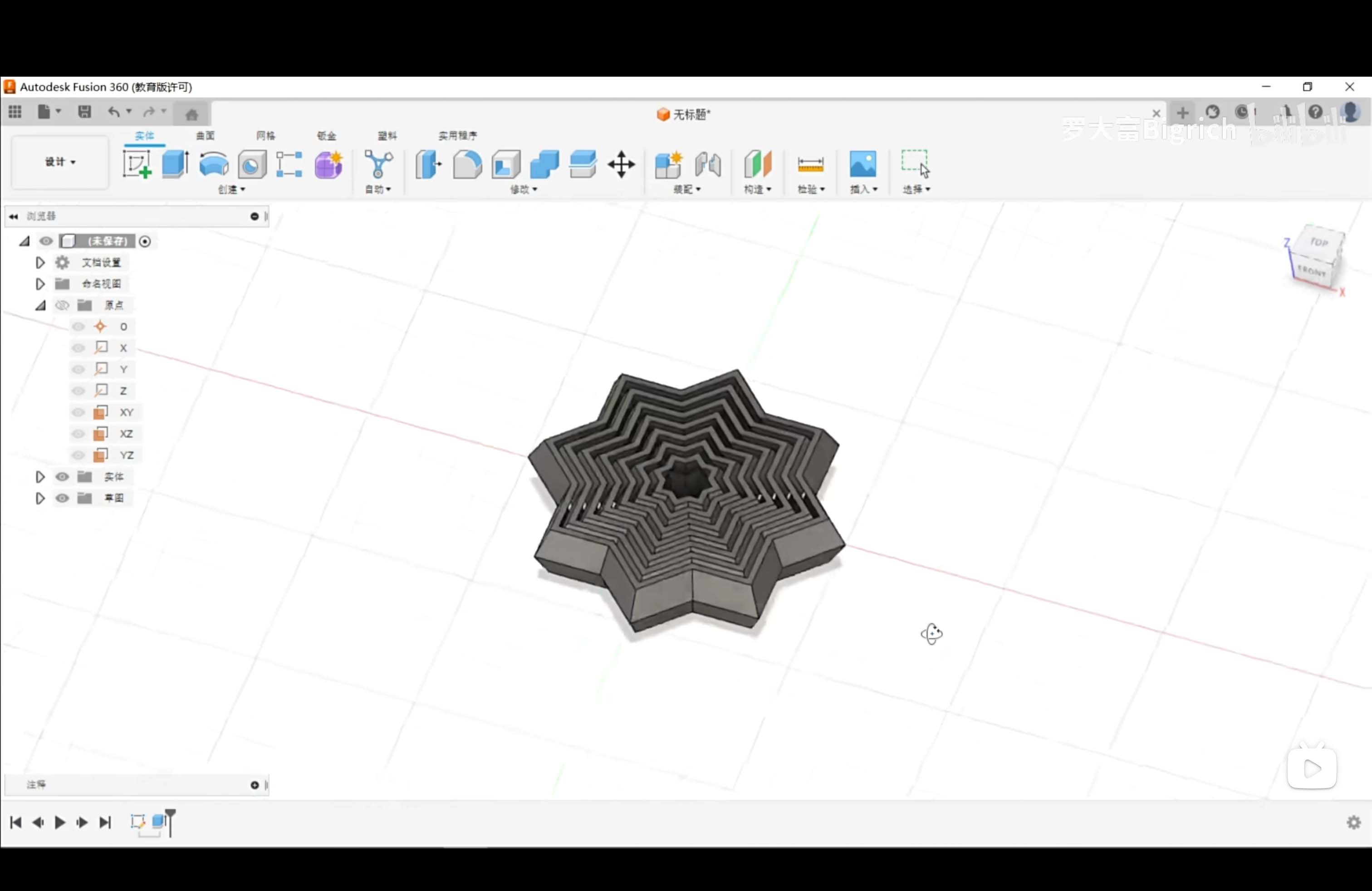
Final Model
Final Result — Animation
Parametric modeling is useful for fabrication because dimensions and relationships remain editable. Changing one parameter can update the entire model, which makes this workflow more flexible than static mesh modeling.
Image and Video Compression
To make the webpage faster to load and easier to browse, all media files were compressed before uploading.
Image Compression — Photoshop
The images were compressed in Adobe Photoshop using File → Scripts → Image Processor. This allowed me to batch process multiple images at once.
- Tool: Photoshop Image Processor
- Export format: JPEG
- Reduced image quality for smaller file size
- Images resized for web documentation
- Color profile converted to sRGB
This reduced the file size while keeping the images clear enough for process documentation.
Video Compression — Jianying / CapCut
The final animation video was compressed using Jianying / CapCut. I reduced the export settings to make the video suitable for online documentation.
- Resolution reduced to 480p
- Frame rate changed to 24 fps
- Bitrate reduced before export
- Export format: MP4
Lowering the resolution, frame rate, and bitrate reduced the final video size and improved webpage loading speed while keeping the animation readable.
Original Design Files
The original source files and exported fabrication files are provided below.
File Formats and Fabrication Logic
Different workflows require different file formats depending on the intended fabrication process.
- PNG / JPG — raster image formats for documentation and presentation
- SVG / AI — vector formats for 2D design and fabrication
- STL — mesh format for 3D printing
- STEP — engineering exchange format for precise 3D geometry
Choosing the correct file format is part of the design process because fabrication tools depend on specific data structures.
Reflection
This week helped me understand the structural differences between raster, vector, and parametric systems.
- Raster = pixel-based visual editing
- Vector = geometry-based 2D precision
- Parametric = constraint-driven 3D modeling
The most important takeaway was that fabrication-oriented design is not only about visual appearance. It depends on clean geometry, editable structure, compatible file formats, and optimized documentation.