Overview
Computer-controlled cutting uses digital files to guide a cutting machine. This week, I used vector files for two different workflows.
- Laser cutting: the laser removes material along vector paths.
- Vinyl cutting: a blade cuts thin adhesive vinyl.
- Both workflows need clean paths, correct scale, and suitable settings.
Group Assignment
The group assignment focused on safety and machine characterization. We tested focus, power, speed, kerf, and joint clearance.
I first used the group kerf logic to set a 2.6 mm slot. After testing the fit, I changed only slot_width to 3 mm.
Full group documentation: Group Assignment Page
Safety Training Reflection
Before cutting, I reviewed the lab safety rules. A laser cutter does not cut by physical contact.
It focuses a high-power beam onto a small material area. The material then burns, melts, or vaporizes along the path.
Wood cutting produces heat, smoke, and burnt edges. So ventilation and supervision are important.
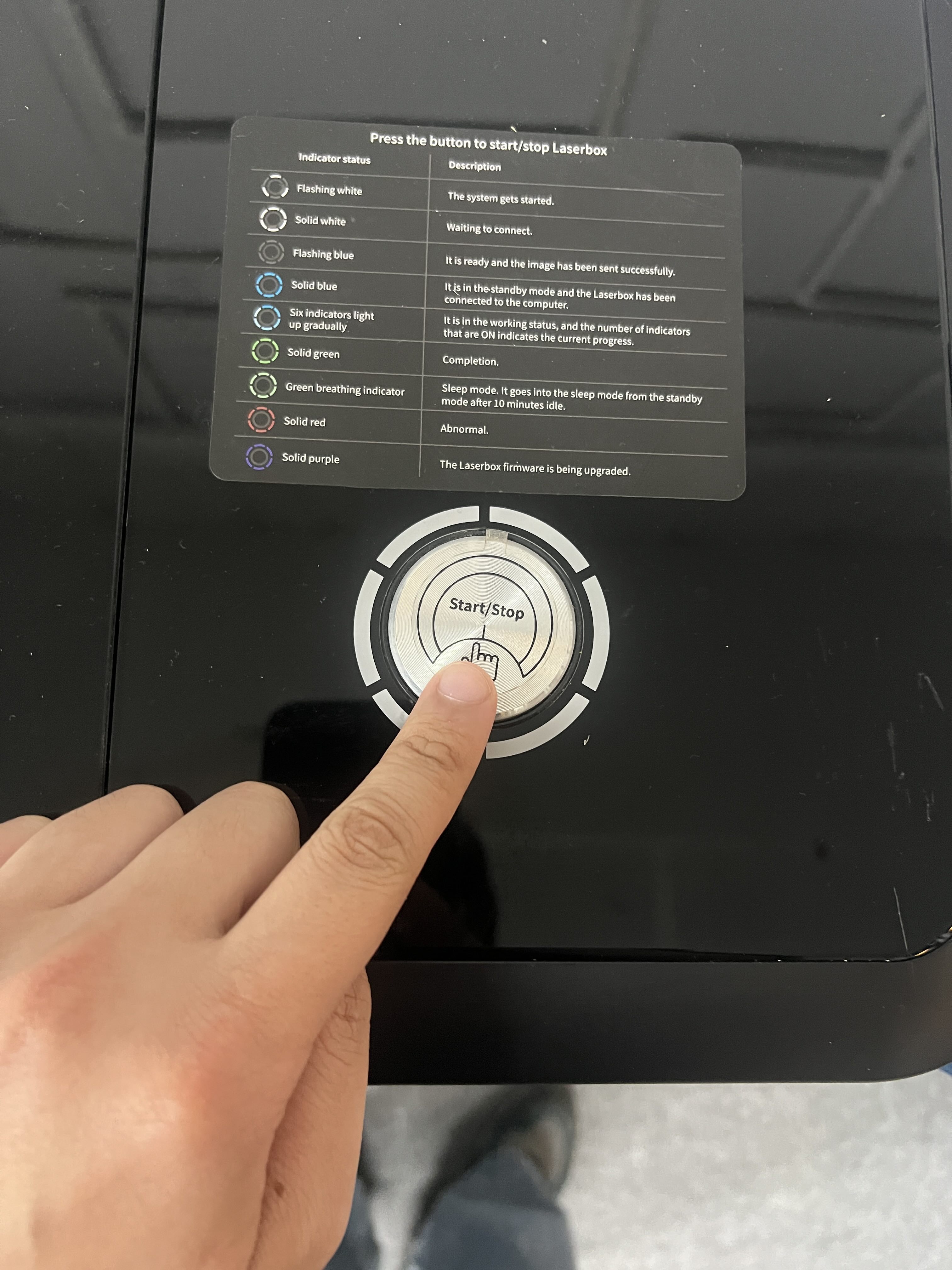
The Laserbox has a Start/Stop button on the top panel. I can press it to pause the job quickly.
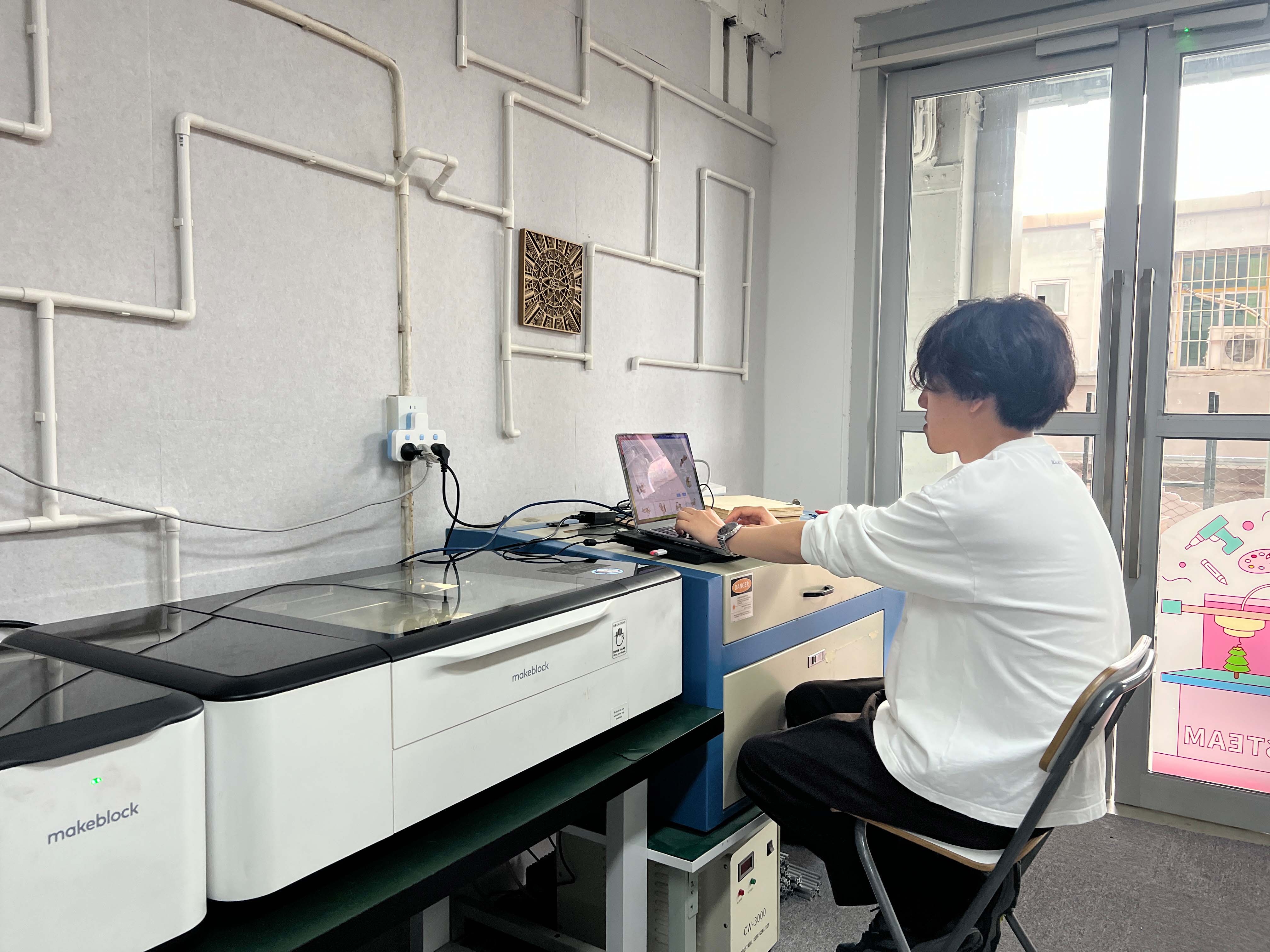
I kept the lid closed during cutting. I also kept the exhaust system active.
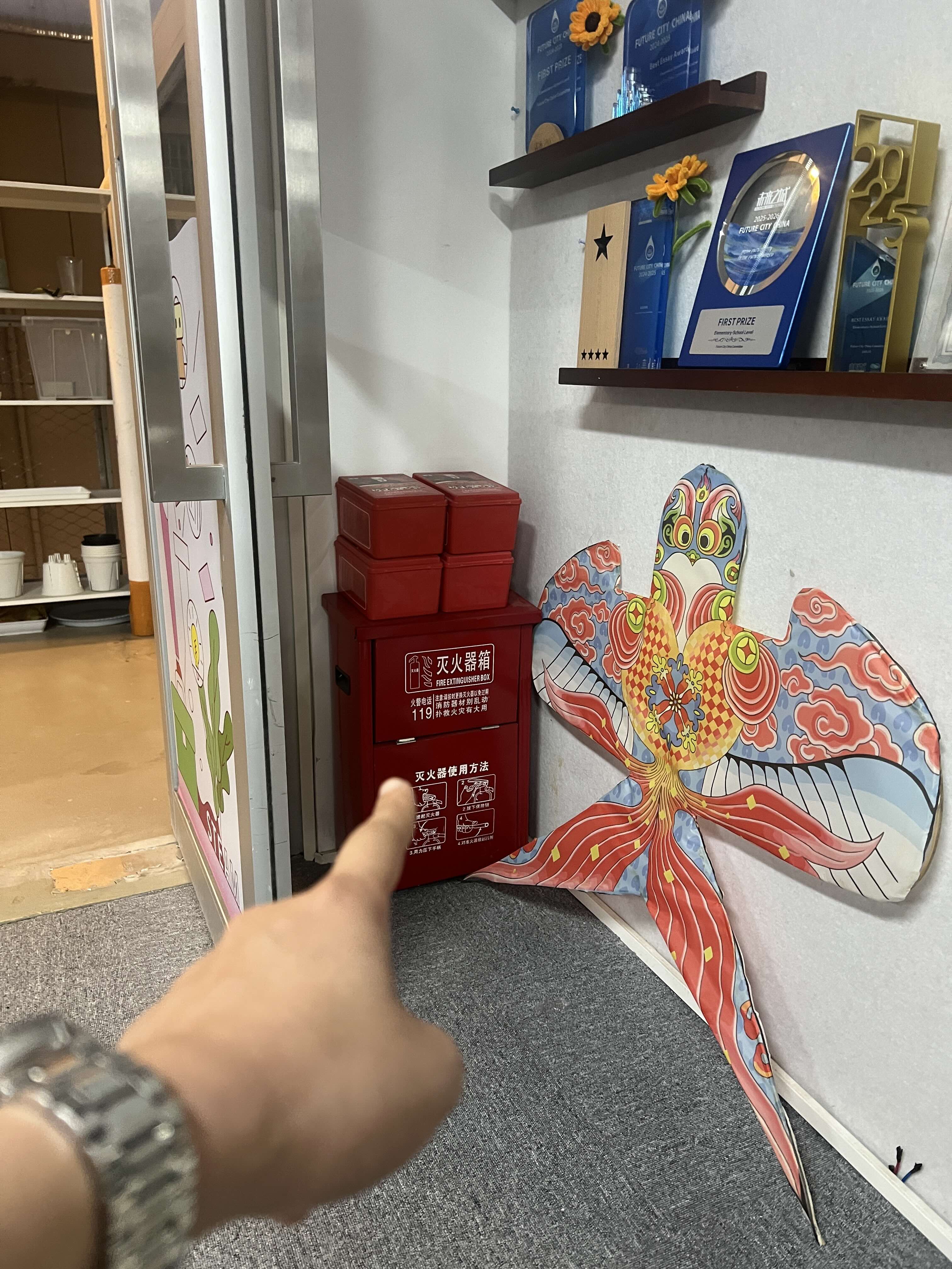
I only used approved wood material. I avoided PVC because it can release toxic and corrosive gas.
Laser Cutting — Makeblock Laserbox
How the laser cutter works
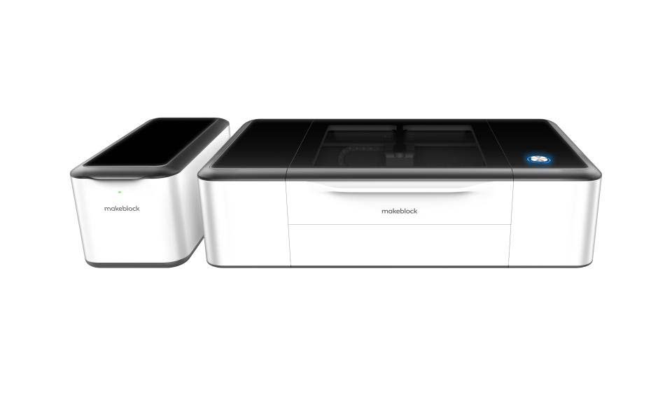
The Makeblock Laserbox uses a CO₂ laser. A lens focuses the beam onto the material surface.
The focused beam follows the vector path. It removes material and creates the cut line.
Cut quality depends on focus, power, speed, passes, material, and machine condition.
Low power or high speed may not cut through. High power or low speed can over-burn the edge.
Machine specifications
| Parameter | Value |
|---|---|
| Model | Makeblock Laserbox |
| Laser type | CO₂ laser |
| Laser power | 40 W |
| Working area | 500 mm × 300 mm |
| Software | Laserbox software |
| Supported file formats | SVG, DXF, PNG, JPG |
| Typical materials | Wood, paper, cardboard, leather, acrylic |
Material used
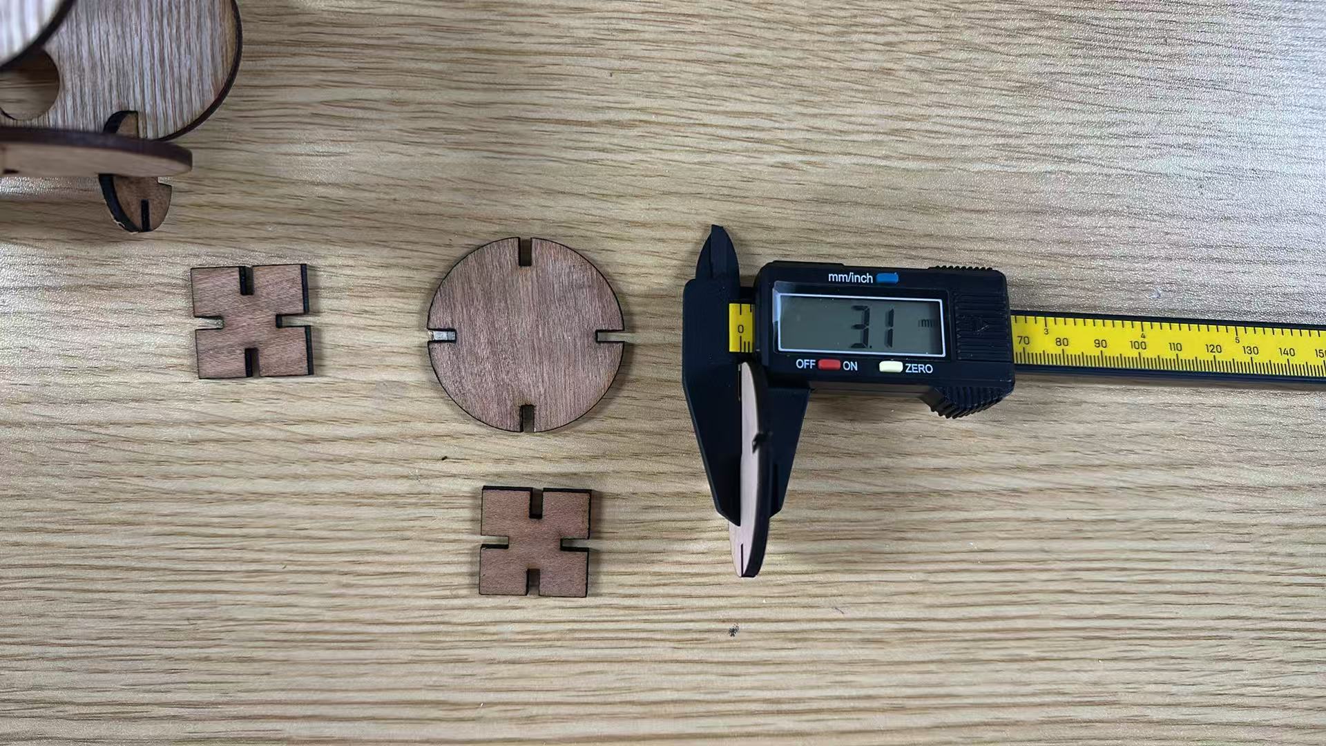
I used a 3 mm basswood sheet. The material label shows the nominal thickness.
Kerf and slot logic
The laser removes a small width of material. This removed width is called kerf.
Kerf matters for press-fit design. It changes the real slot size after cutting.
I first tried a 2.6 mm slot. The parts connected, but did not insert deeply.
Then I tested a 3 mm slot. This helped me compare the fit with the real material.
| Item | Value | Use |
|---|---|---|
| Material thickness | 3 mm | Base sheet thickness |
| Kerf | 0.2 mm | Group characterization value |
| First slot width | 2.6 mm | First test based on kerf |
| Second test slot width | 3 mm | Second fit test |
Individual Assignment
My individual work had two outputs. I made a vinyl sticker and a parametric press-fit kit.
Parametric Press-fit Construction Kit
Design goal
I wanted to build a modular kit with simple geometric parts. The kit uses circles, rectangles, and oval body panels.
I designed the kit in Fusion 360. I used named parameters instead of fixed dimensions.
The parameters control slot width, slot depth, circle diameter, and body size.
Parametric settings in Fusion 360
I first used slot_width = material - kerf - clearance. This gave me a 2.6 mm slot.

I kept this first value for the first assembly test. Then I checked how the parts actually fitted.
| Parameter | Expression / Value | Purpose |
|---|---|---|
| material | 3 mm | Material thickness |
| kerf | 0.2 mm | Reference kerf value |
| clearance | 0.2 mm | First fit adjustment |
| slot_width | 2.6 mm, then 3 mm | Slot width test |
| diameter | 28 mm | Circle size |
| slot_depth | diameter / 4 | Slot depth |
| slot_count | 4 | Slot quantity |
| body_width | 50 mm | Oval width |
| body_height | 90 mm | Oval height |
Why this is parametric
This design is parametric because key dimensions use named values. I can change them from one table.
I first set slot_width to 2.6 mm. Later, I changed it to 3 mm for another test.
The slot update applied to the circle, rectangle, and oval modules. I did not redraw each slot.
Circle module
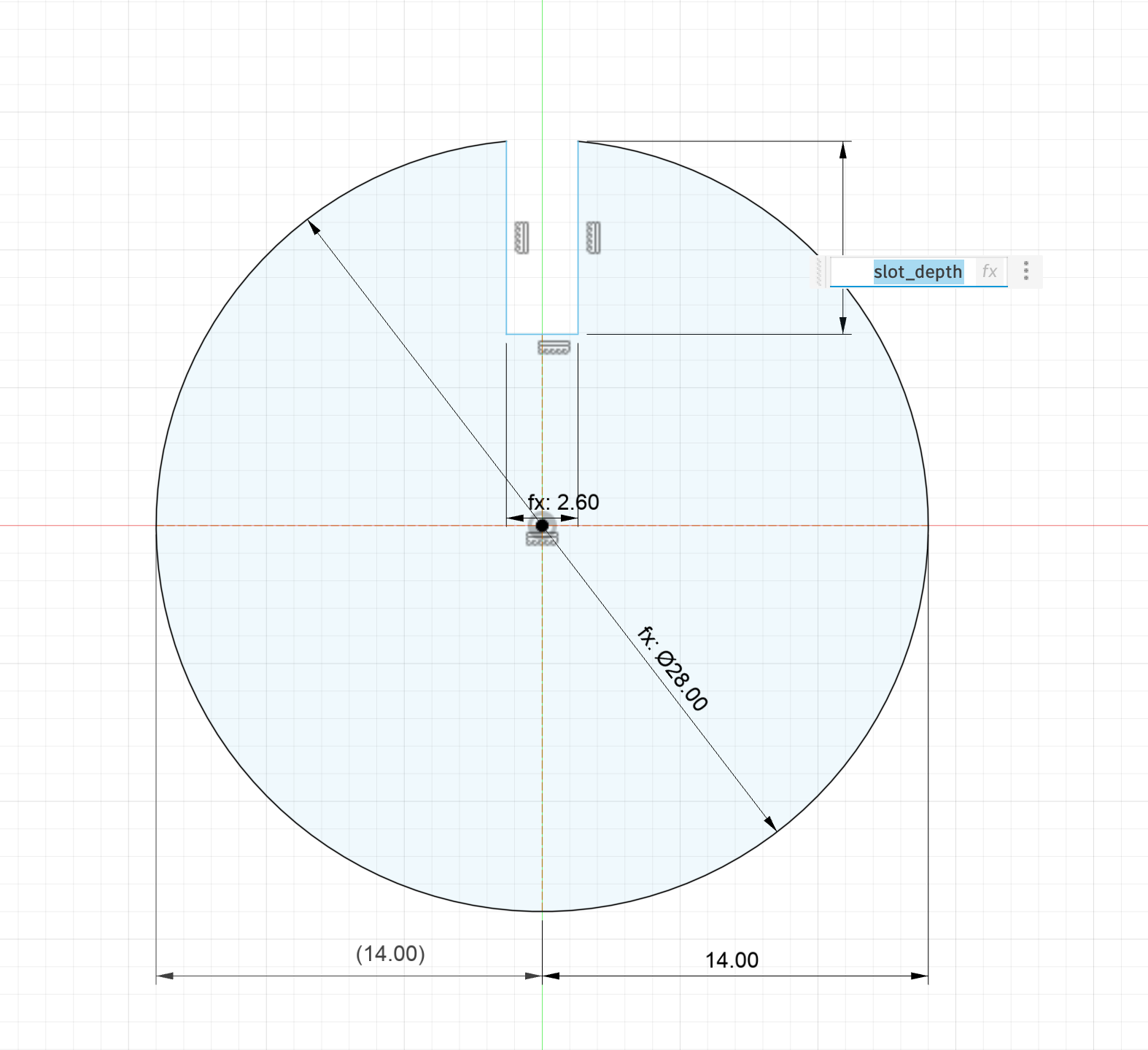
I started with a circle module. The diameter parameter controlled the circle size.
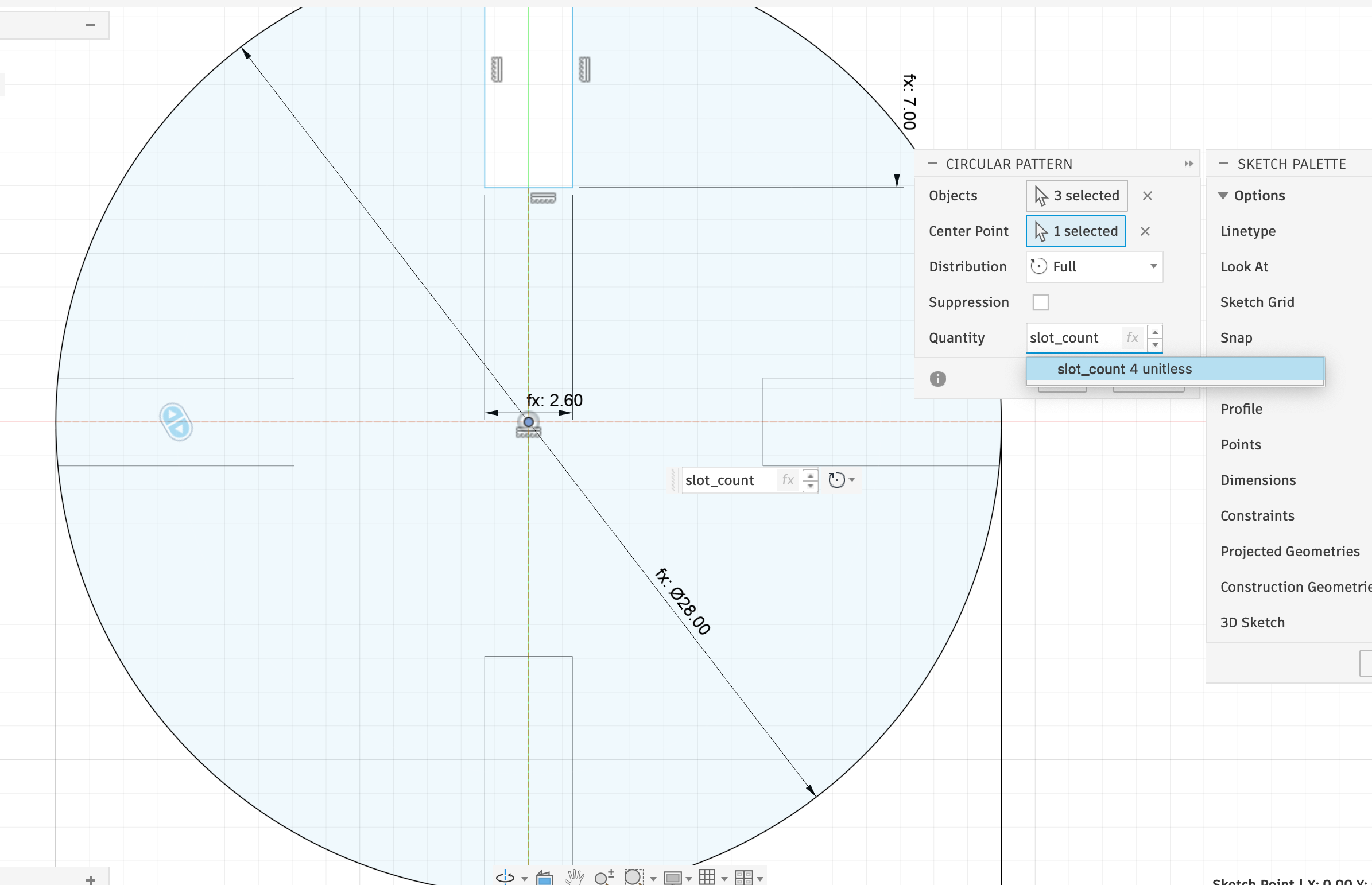
I drew one slot first. Its width used slot_width, and its depth used slot_depth.
Then I used Circular Pattern. The slot_count parameter controlled the repeated slots.
Oval and connector modules
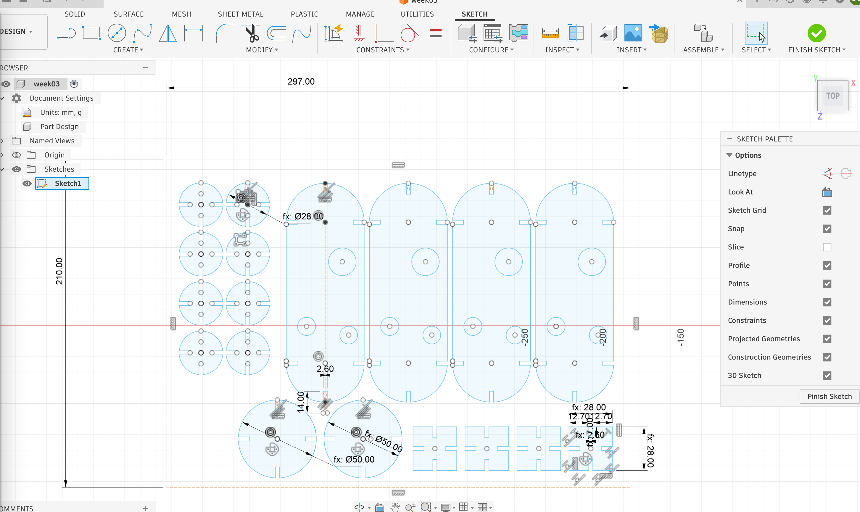
I then made oval body panels and rectangular connectors. All modules used the same slot_width parameter.
This kept the connections consistent. It also made the parts easier to combine.
Exporting the cutting file
I arranged the parts inside an A4 boundary. This matched the file to the real sheet.
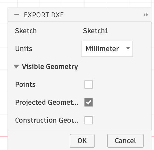
I exported the sketch as a DXF file. The export unit was millimeter.
Laserbox preparation
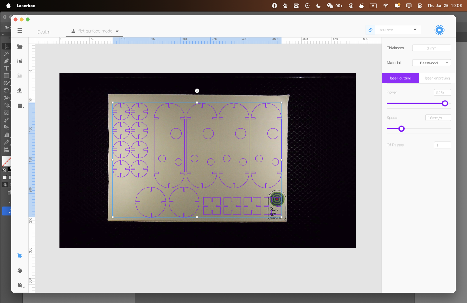
I imported the DXF file into Laserbox software. I checked the layout with the camera view.
The material was set to 3 mm basswood. I used 95% power, 16 mm/s speed, and 1 pass.
Laser cutting settings
| Item | Value |
|---|---|
| Material | Basswood |
| Thickness | 3 mm |
| Operation | Vector cutting |
| Power | 95% |
| Speed | 16 mm/s |
| Passes | 1 |
| Focus | Auto focus |
| Ventilation | Enabled |
Removing the parts
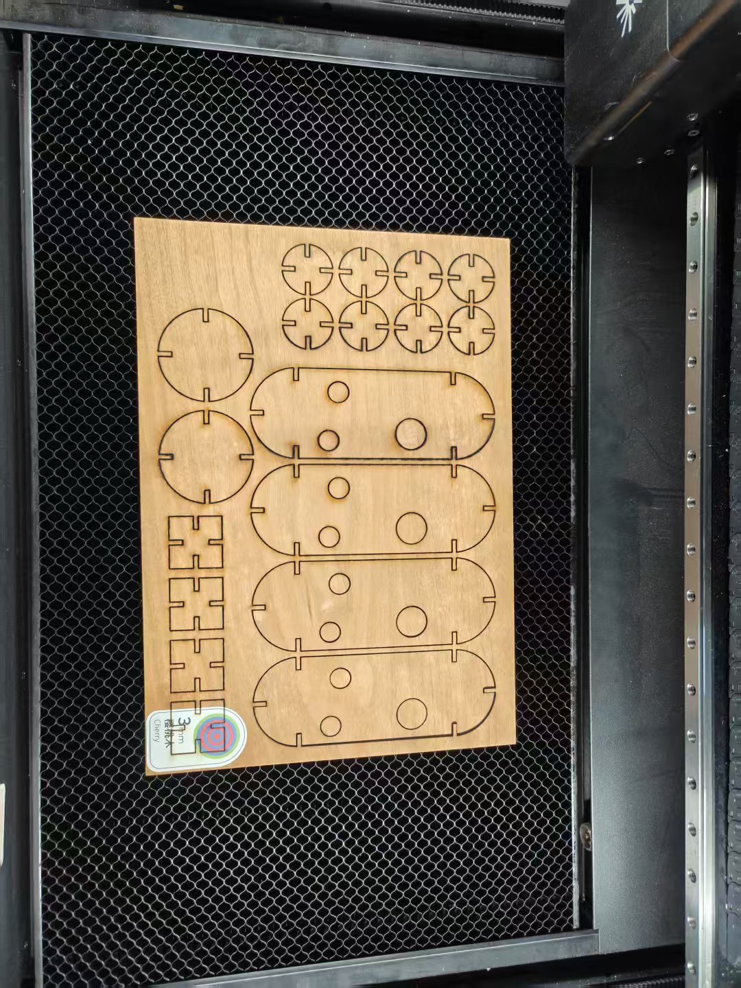
After cutting, I removed the parts from the sheet. The final settings cut through the 3 mm basswood.
2.6 mm slot test
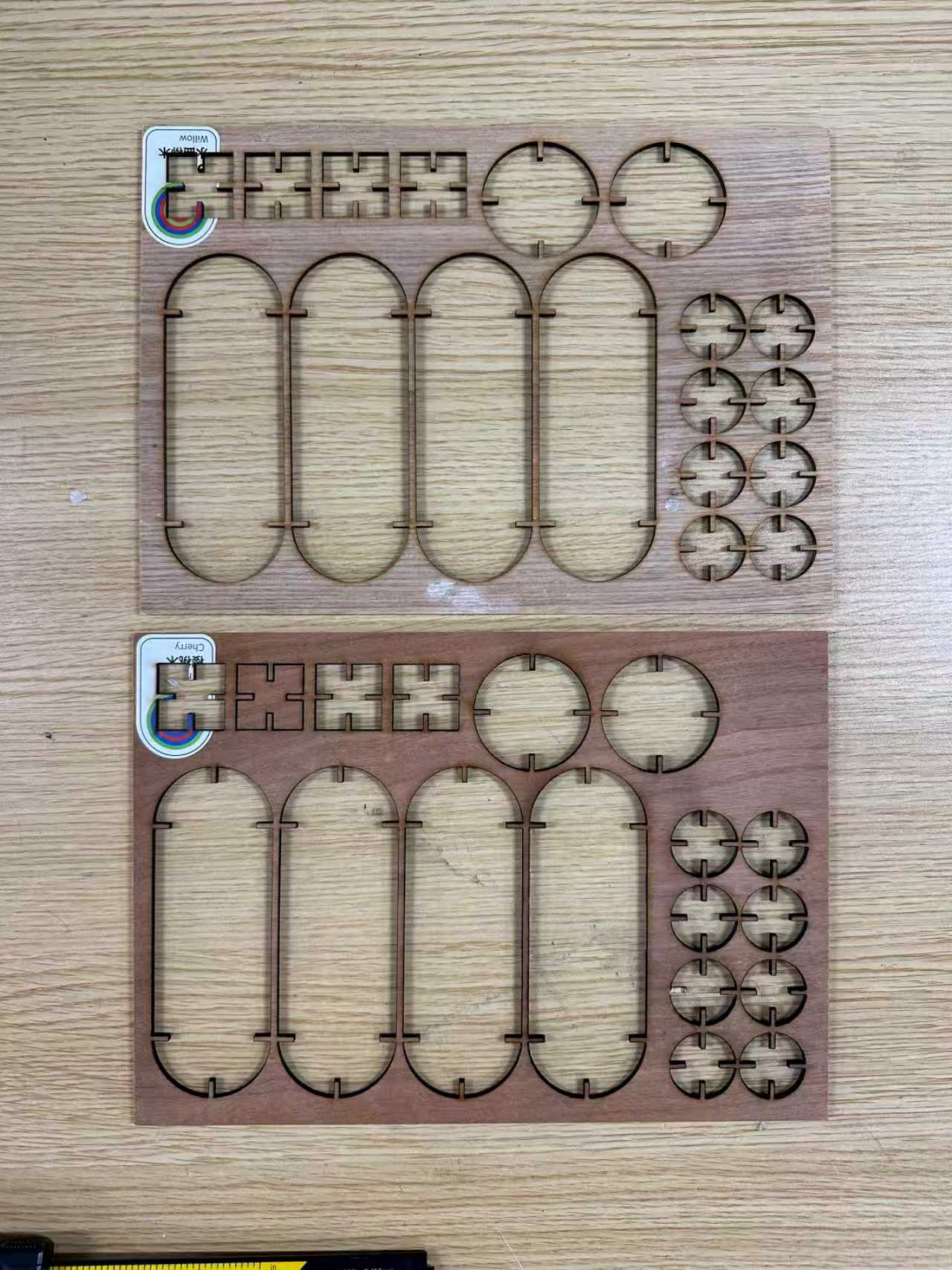
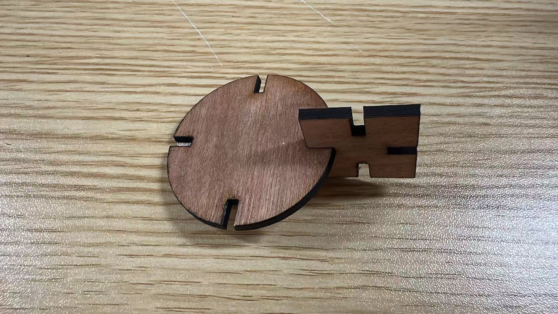
I first assembled the kit with the 2.6 mm slot. The parts could connect.
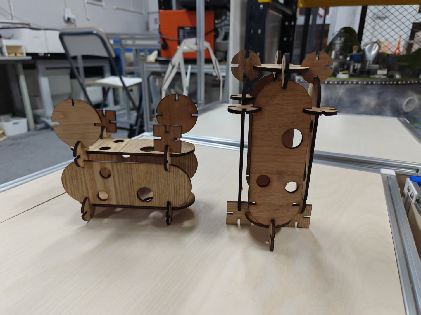
I then checked the joint more closely. The pieces were not fully inserted into the slot.
Changing one parameter to 3 mm
I did not redraw the slots. I only changed slot_width to 3 mm in Fusion 360.

3 mm slot assembly test
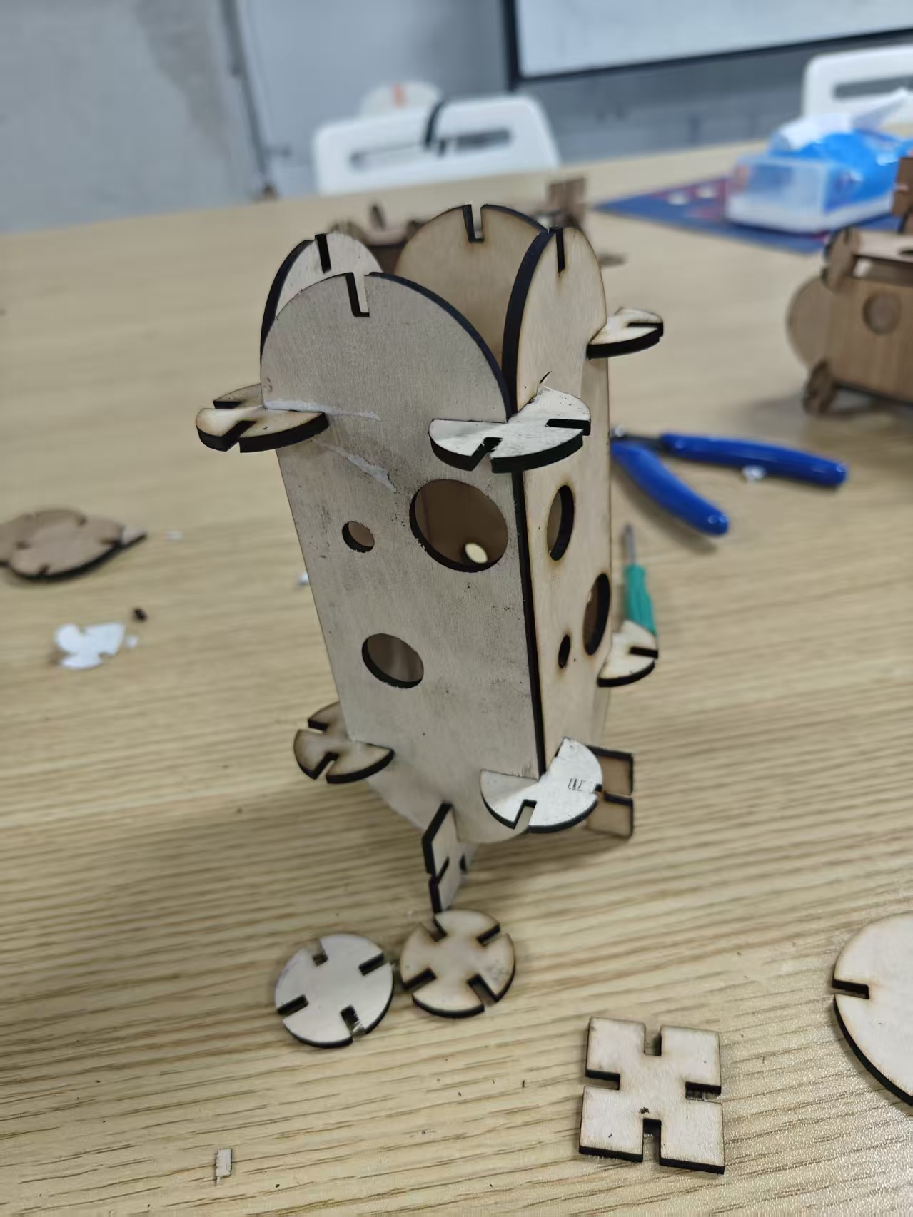
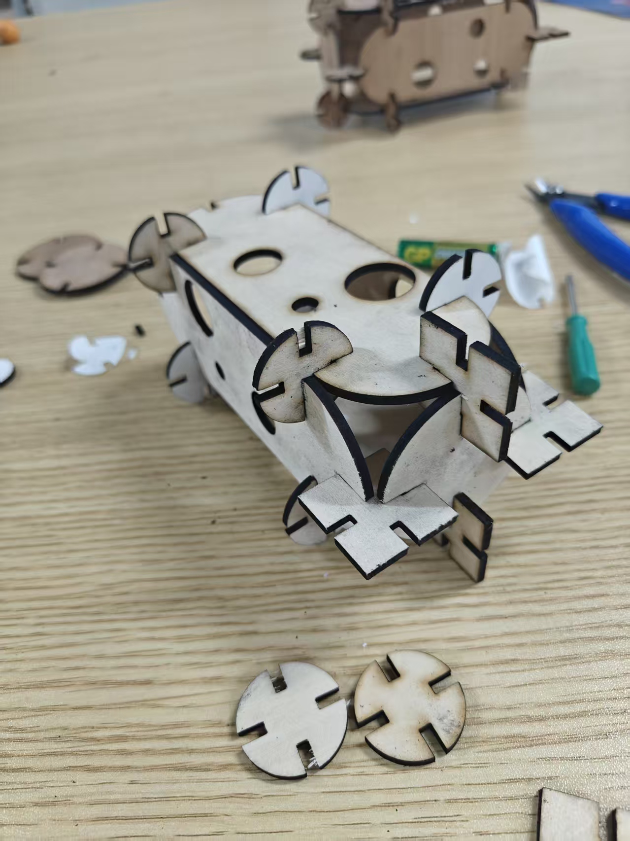
The 3 mm slot matched the material better. The pieces inserted more fully.
Vinyl Cutting — Silhouette Cameo 5a
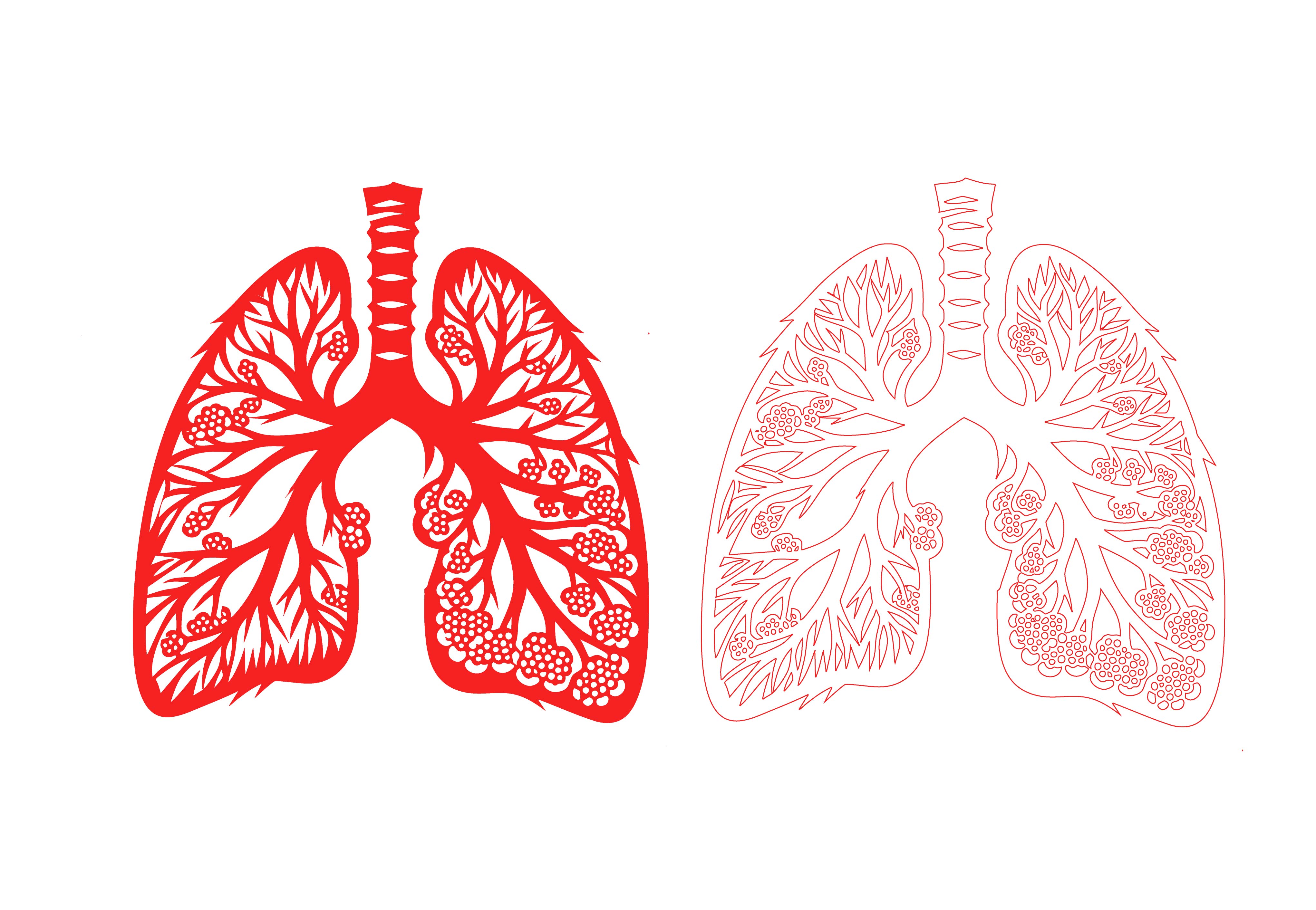
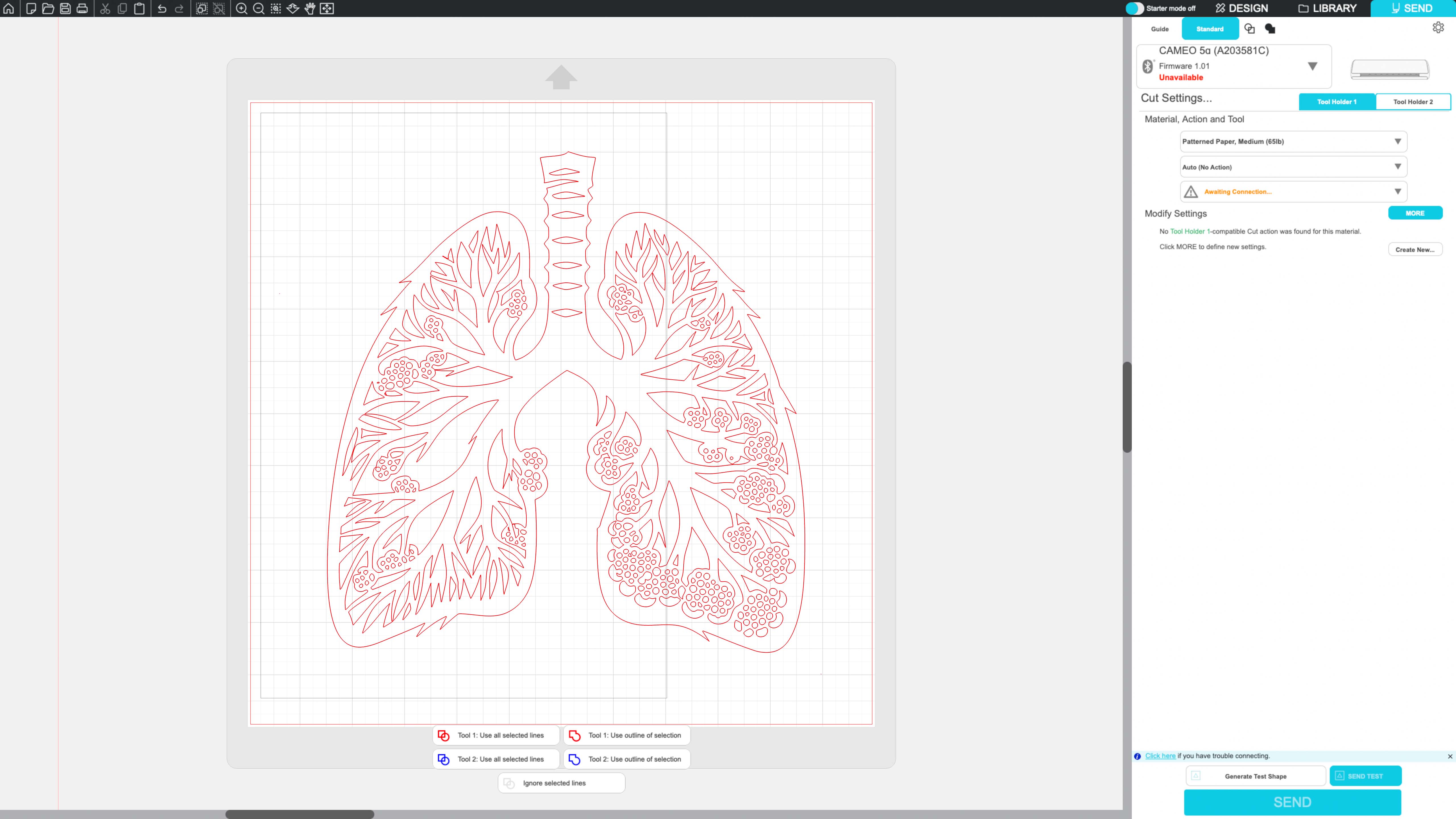
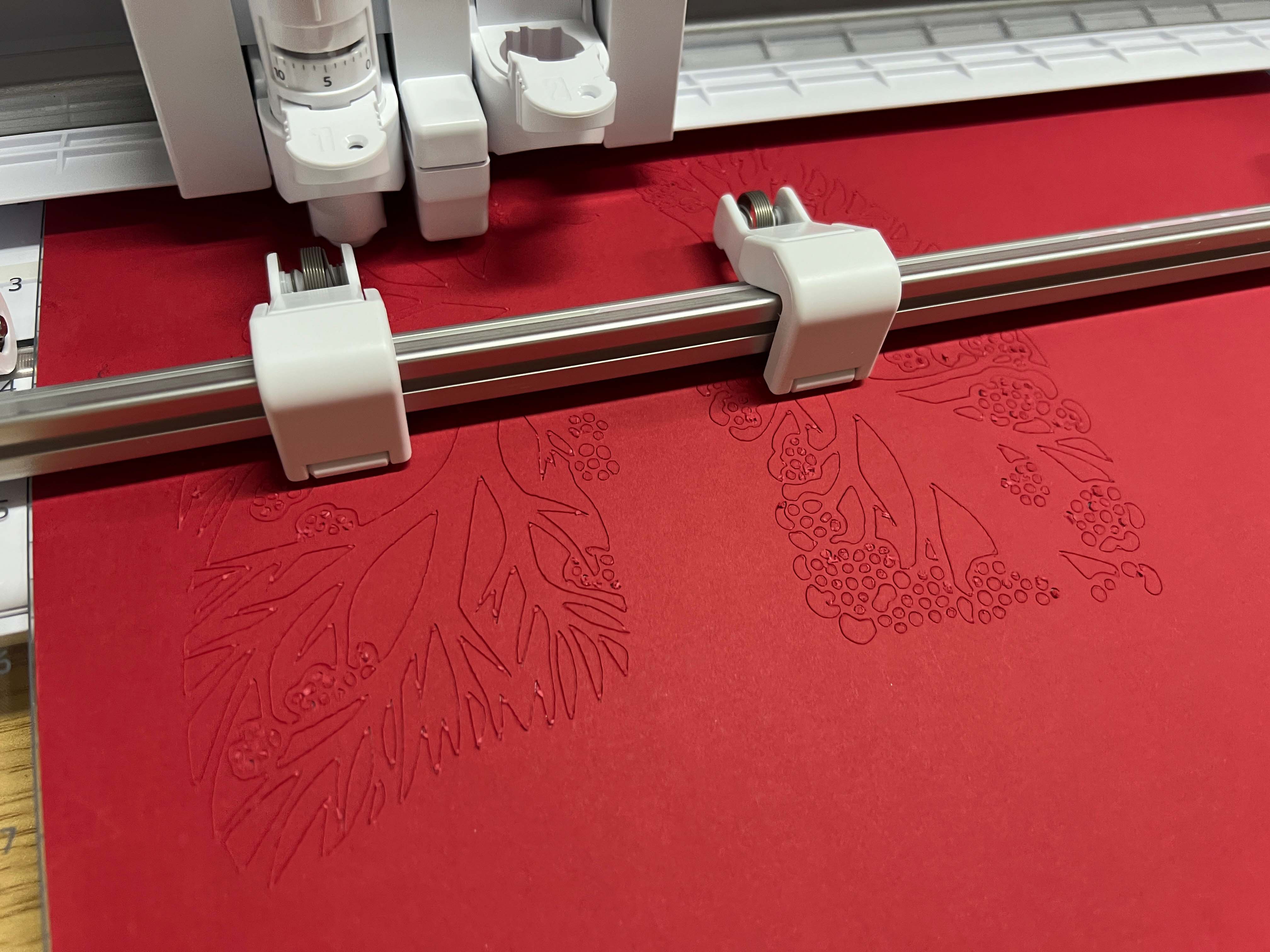
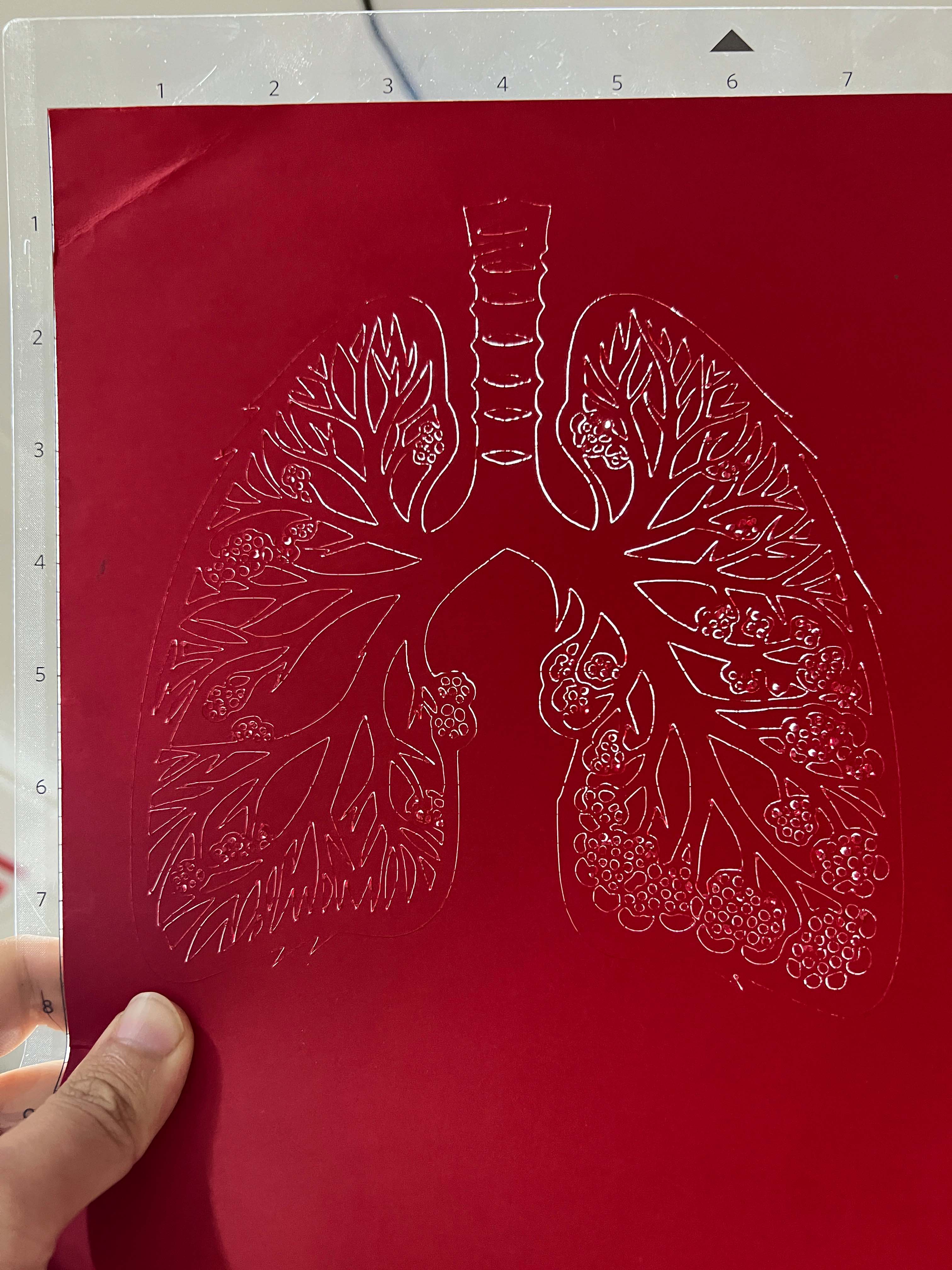
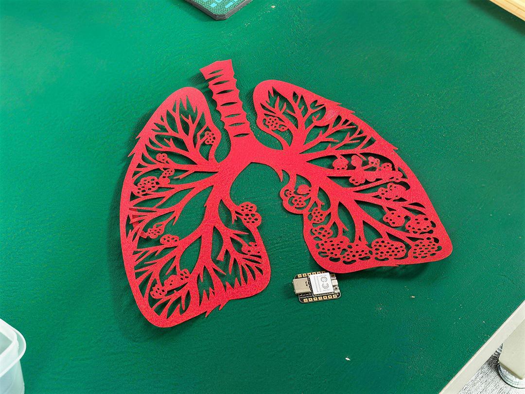
For vinyl cutting, I made a lung-shaped sticker. The branching details tested cutting and weeding.
Vector design
File format issue
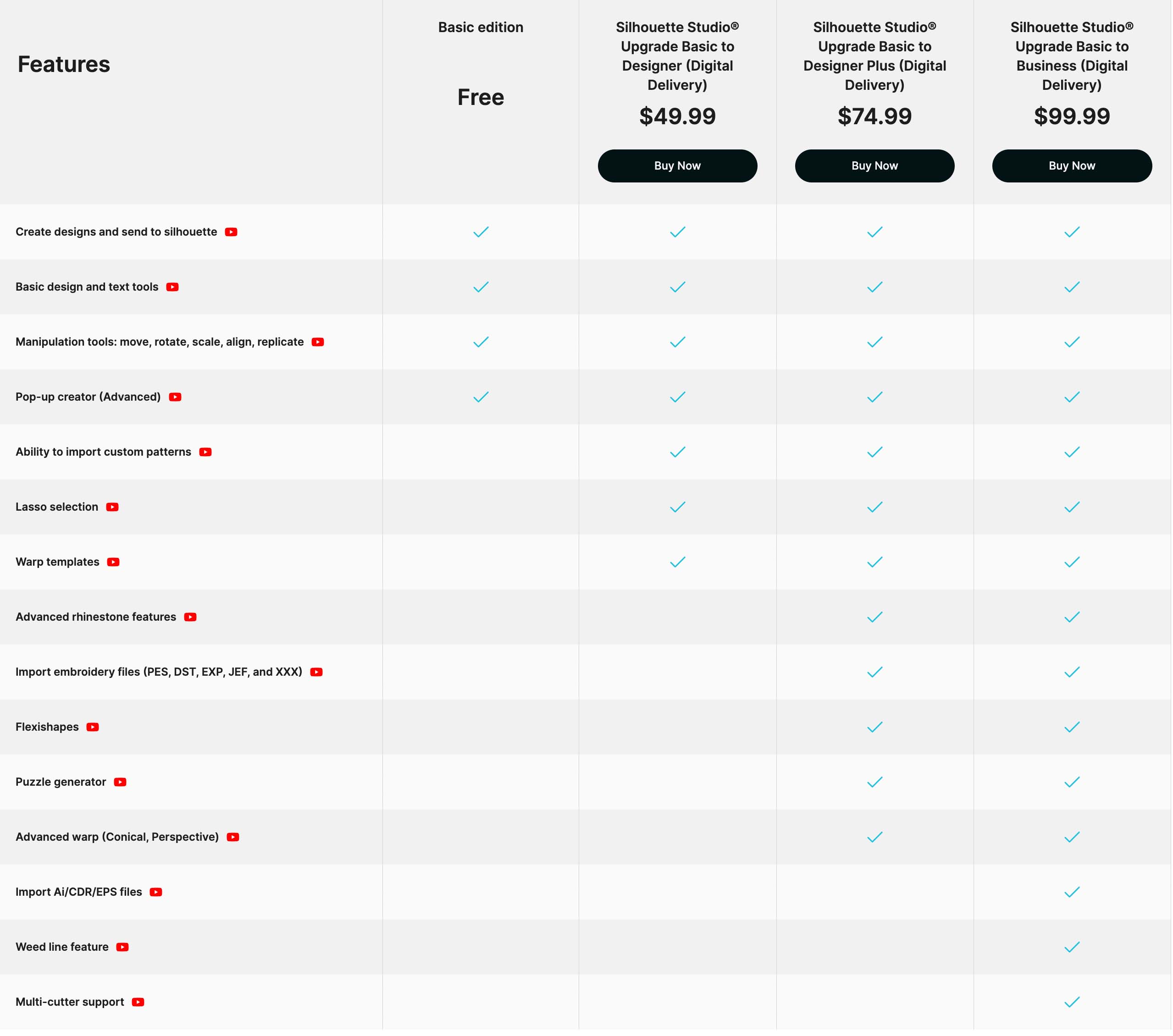
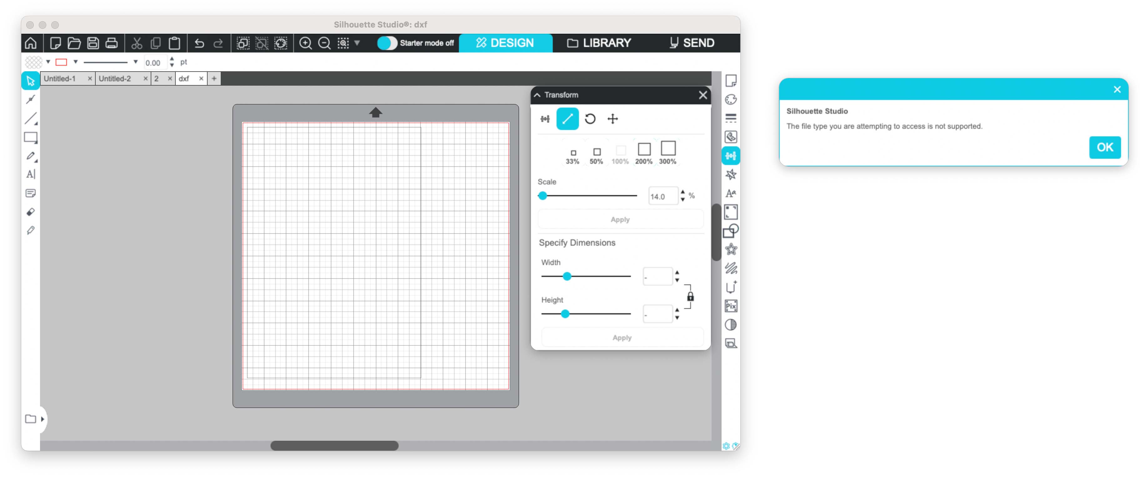
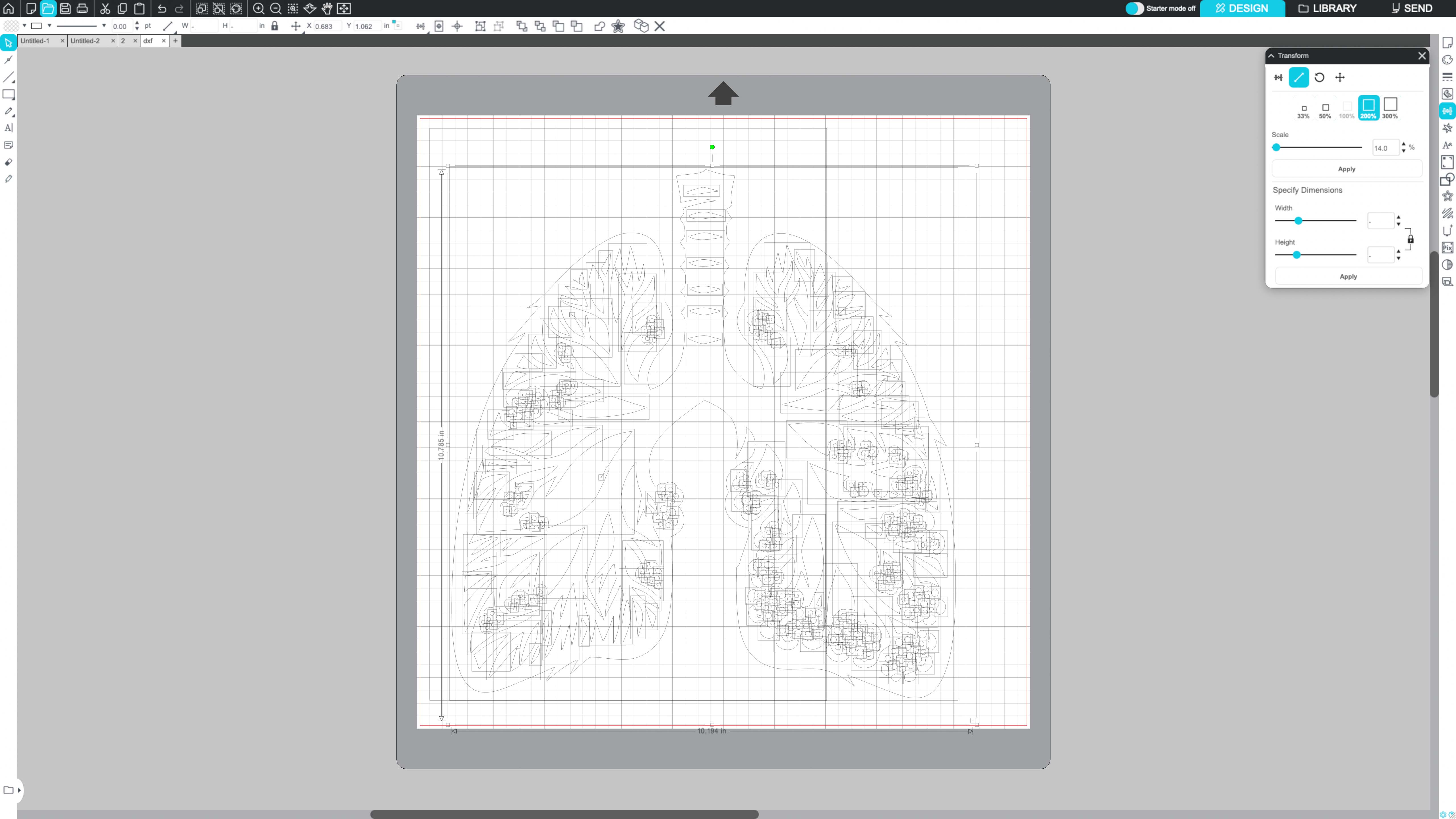
Silhouette Studio Basic did not support some vector formats. I exported the design as DXF.
Importing the design
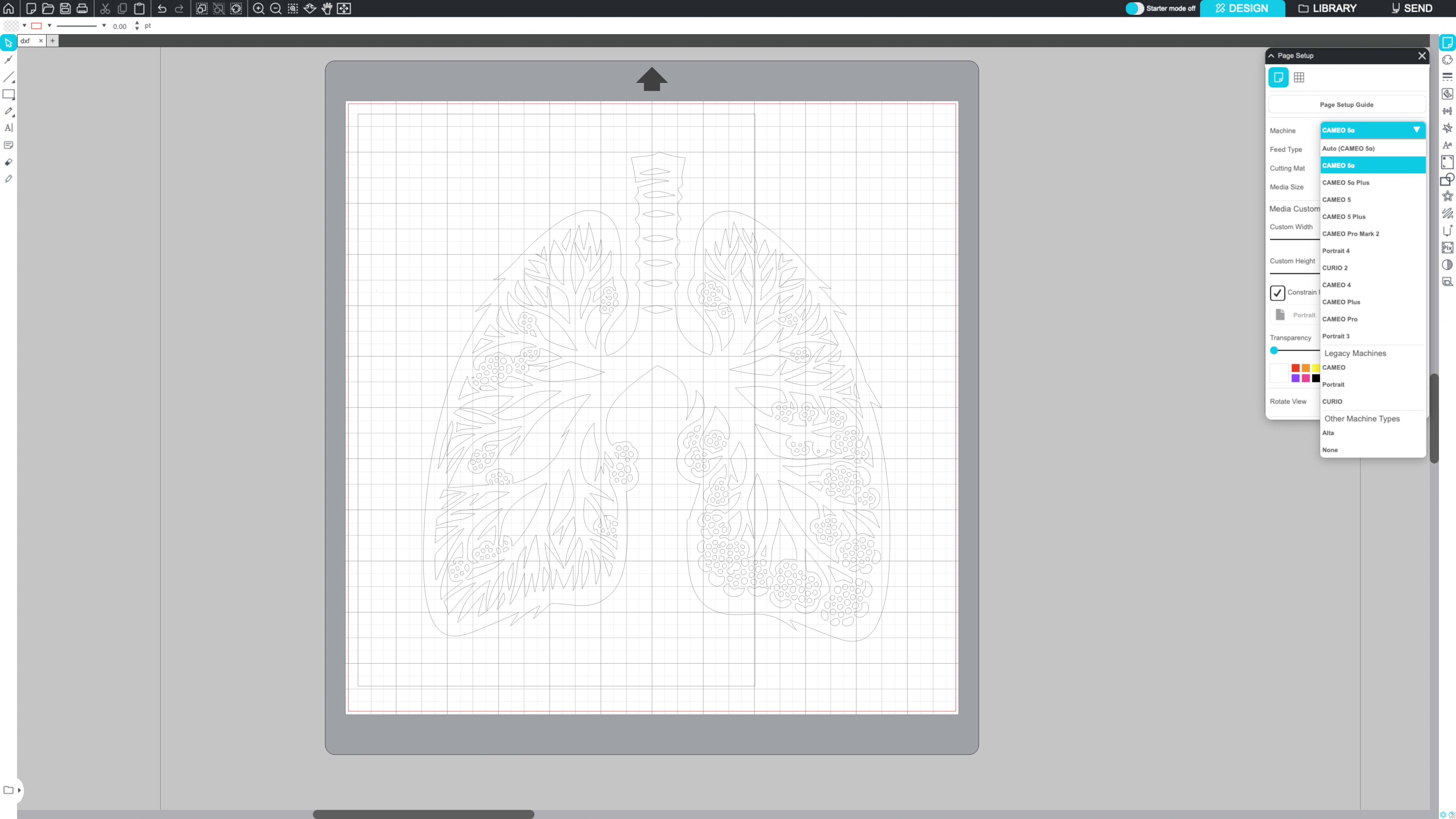
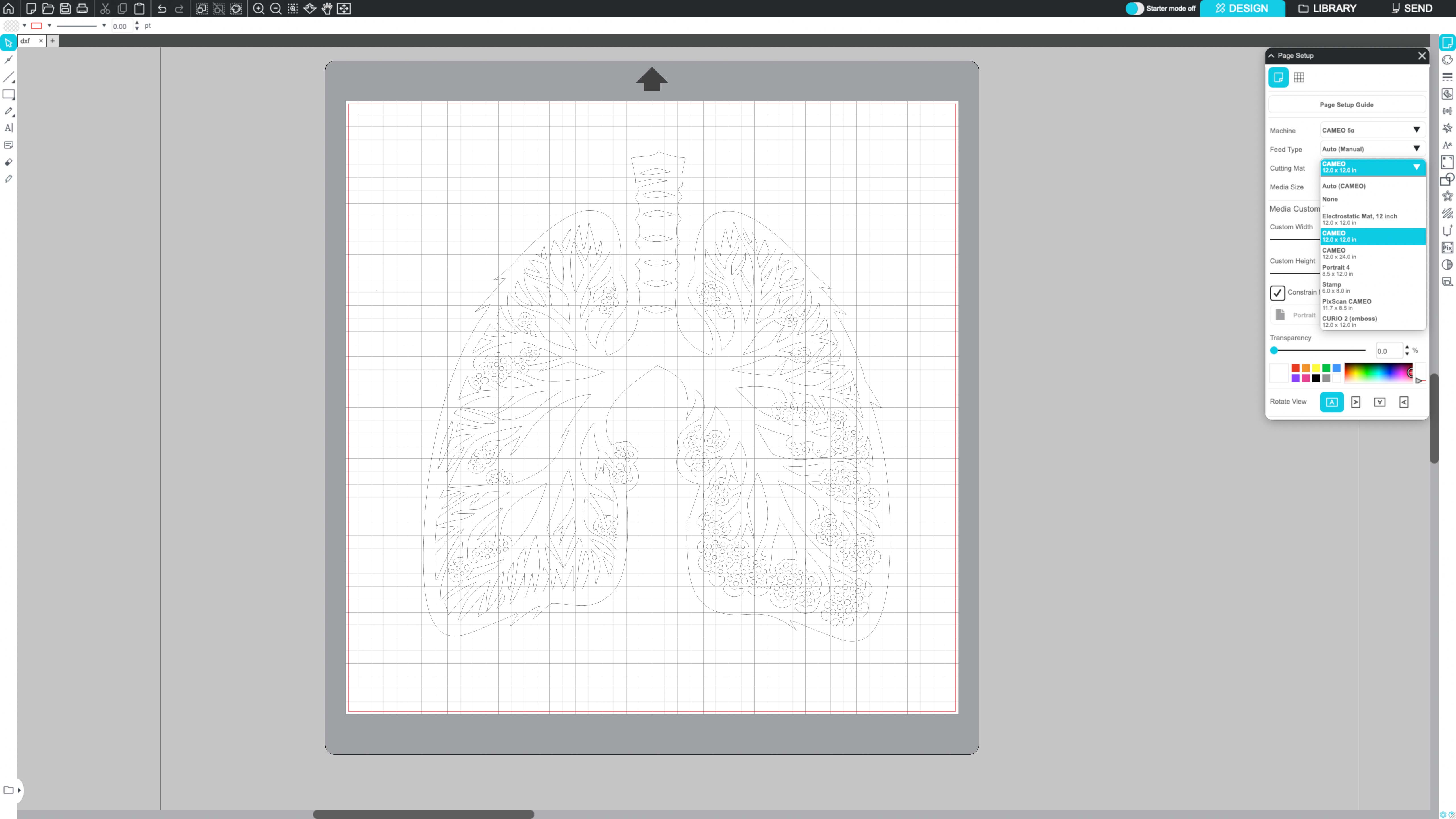
Machine setup
- Select machine model: Cameo 5a
- Set the cutting mat size
- Select the vinyl material type
- Check blade force, speed, and cut depth
Preparing material
Cutting process
Weeding
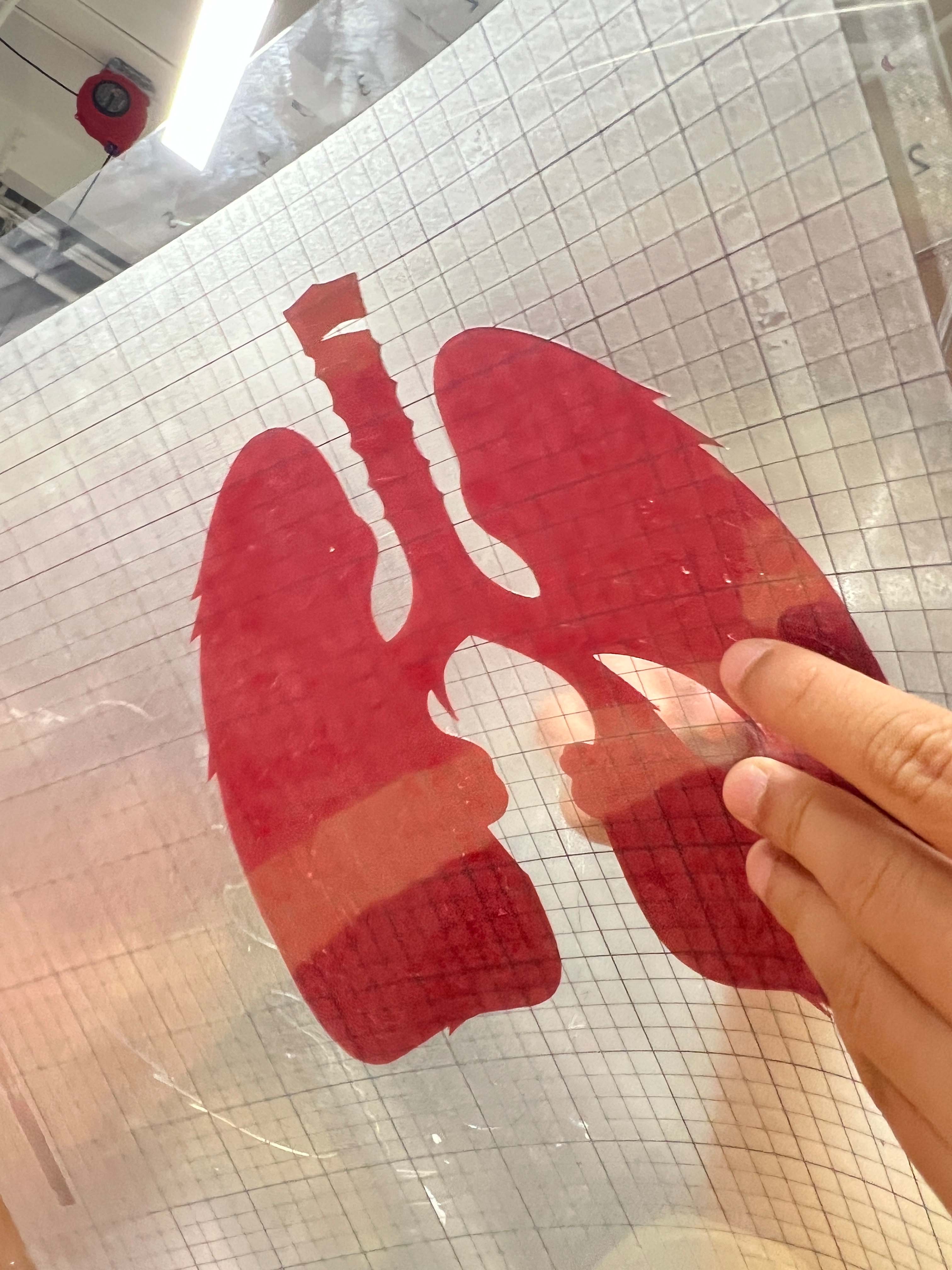
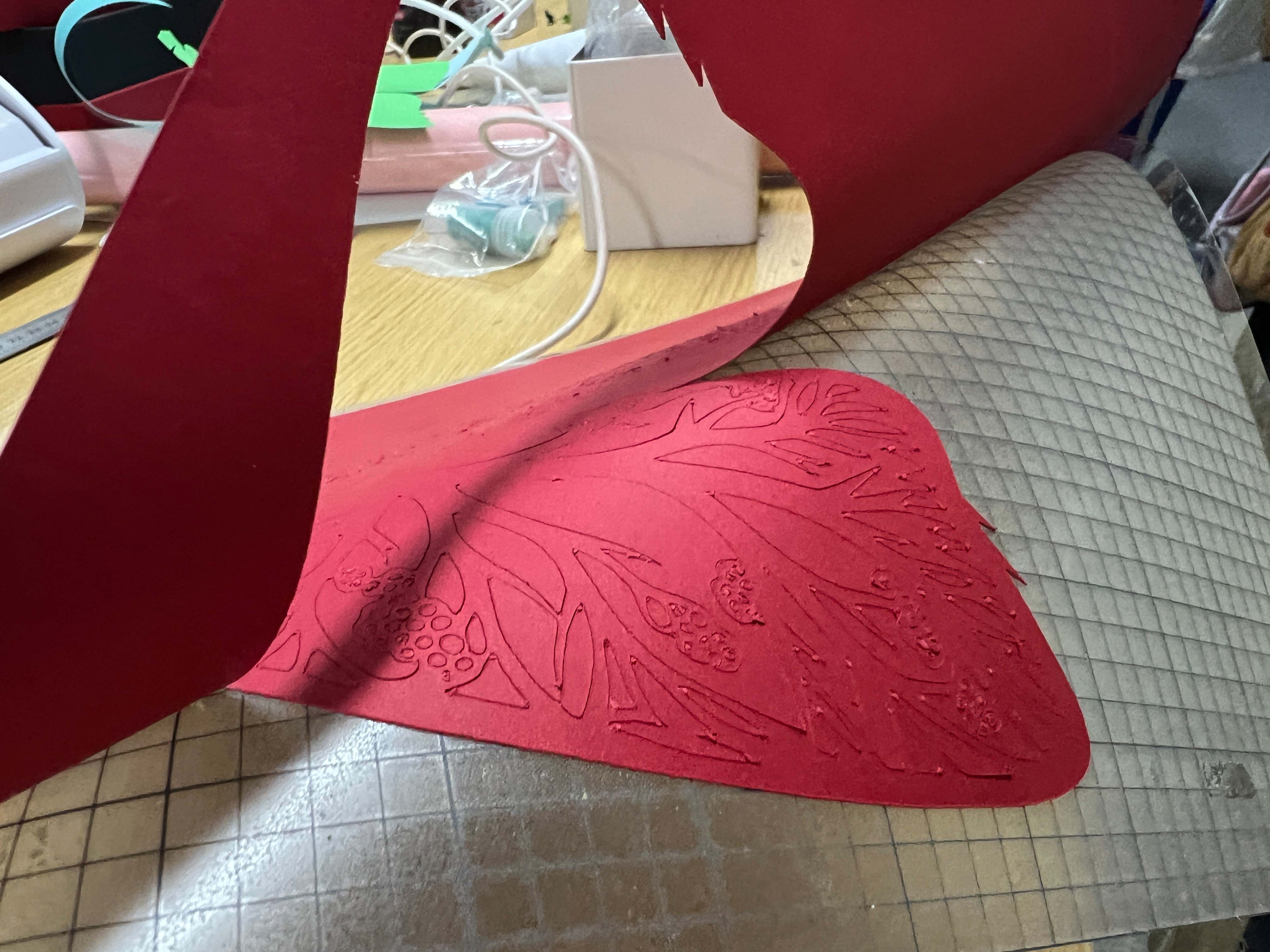
After cutting, I removed the unwanted vinyl. This process is called weeding.
The branching details made weeding slower. Small pieces can lift if pulled too quickly.
Final result
Design Files
These files include the editable design and cutting files.
AI Use Statement
I used AI to organize the documentation and improve the English wording. I made the CAD, cutting, photos, and assembly myself.
AI was not used to fabricate the parts. It was only used for writing support.
Reflection
- The first 2.6 mm slot did not fully engage.
- The 3 mm slot fitted the material better.
- Parameters made the slot update faster.
- The same parts could build more than one structure.
- Vinyl cutting needed clean vectors and careful weeding.