Week 07
Computer-Controlled Machining
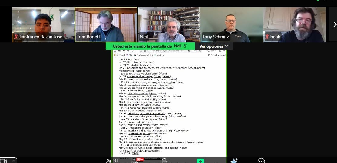
Class with Neil
During Week 07 – Computer-Controlled Machining of the Fab Academy, we learned about the fundamentals of manufacturing large parts using CNC machines. The class focused on the workflow from CAD design to CAM toolpath generation, as well as key machining parameters such as feed rate, spindle speed, tool selection, and safety considerations when operating CNC routers.
This week we also had guest presentations from Tom Bodett and Tony Schmitz. Tom Bodett shared insights about creativity and communication in the development of ideas and projects. Tony Schmitz, a professor at the University of Tennessee and an expert in advanced manufacturing, spoke about machining dynamics and how research helps improve precision and efficiency in CNC machining processes.
Overall, this week helped me understand how computer-controlled machining allows the fabrication of large and precise components, which is essential for building structural parts and prototypes in digital fabrication projects.
Group Assignment:
°Complete your lab's safety training
° Test runout, alignment, fixturing, speeds, feeds, materials and toolpaths for your machine
° Document your work to the group work page and reflect on your individual page what you learned
Have you answered these questions?
- I. Linked to the group assignment page. ✅
- II.Documented how you designed your object and made your CAM-toolpath✅
- III.Checked your board can be fabricated ✅
- IV. Documented how you milled and assembled your final product (including setting up the machine, fixturing, feeds, speeds etc.). ✅
- V. Described problems and how you fixed them ✅
- VI.Included your design files and 'hero shot' of your final product✅
Group Assignment Sumary
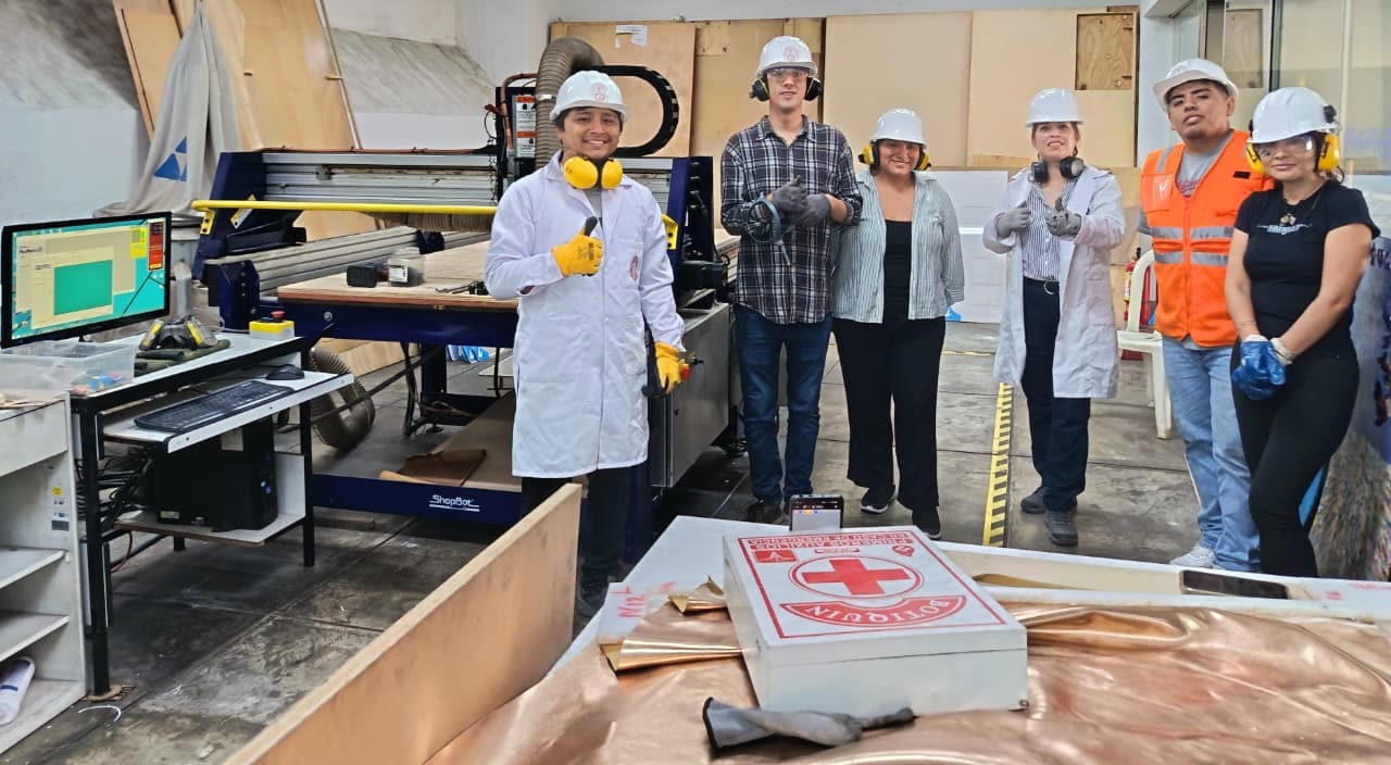
Before starting the individual work for Week 07 – Computer-Controlled Machining of the Fab Academy, our group organized a virtual meeting with instructors of the Fab Lab ifourniture, Evelyn Cuadrado y Cristian Loayza the day after the theoretical class to attend the Lab’s Safety Training. During this session, we learned about the essential safety measures required when working in the laboratory, including proper behavior, risk awareness, and the importance of maintaining a safe and organized workspace. We were also introduced to the meaning of different safety signs used in laboratories and workshops: red indicates danger or emergency situations such as machine shutdown systems, blue represents mandatory actions like the use of personal protective equipment (PPE), yellow signals warnings or potentially hazardous areas, and green identifies safe conditions or locations of first aid equipment. This training helped us better understand how to work safely when using digital fabrication machines.

Group Assignment Sumary
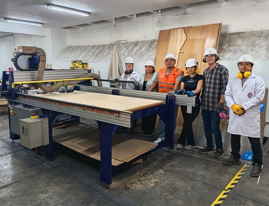
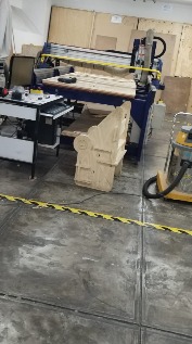
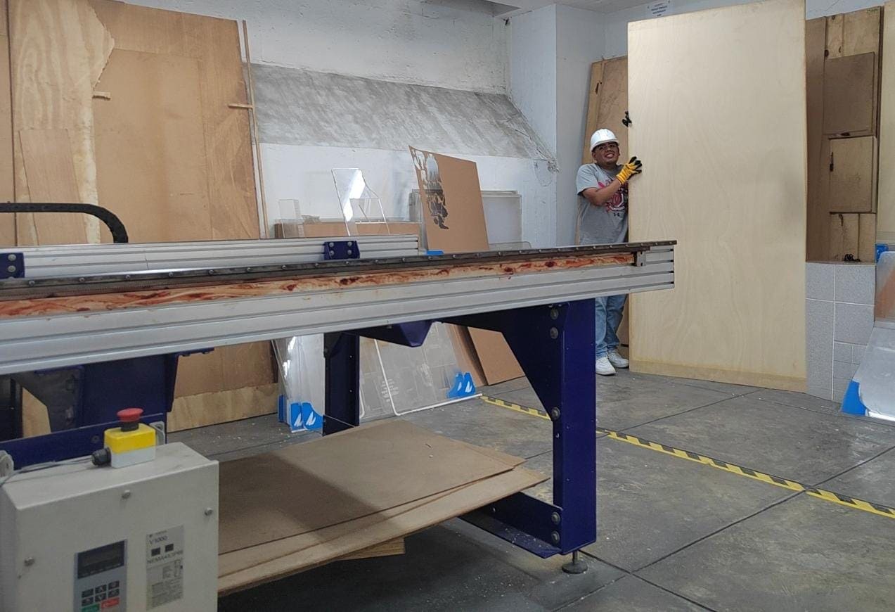
Later, we met in person at the FabLab UNI to carry out the group assignment. At the beginning of the session, we received an additional safety briefing before operating the ShopBot PRSalpha 96-48 CNC router, where we reviewed the proper procedures and precautions needed to safely work with large computer-controlled machines in the lab.
Here is the link to learn more about the group project.
📟Group Challenges
During the group work, one of the main challenges was coordinating the use of the CNC machine and organizing the workflow among team members. Since several people needed to use the equipment, we had to carefully plan the machining times and preparation steps to avoid delays.
Another challenge was ensuring that everyone correctly understood the CNC preparation process, including setting the X, Y, and Z axes, fixing the material properly on the machine bed, and verifying the toolpaths before starting the cutting process. Small mistakes in these steps could affect the machining results.
Through collaboration and discussion, we were able to solve these issues by helping each other review the machine setup, checking the files before cutting, and sharing our observations during the fabrication process. This teamwork helped us achieve more accurate and safer results when using the CNC router. ⚙️🪵
🔍 1. Individual Refletion
During this assignment, I understood the importance of following safety procedures when working with fabrication tools and CNC machines. Applying safety measures and paying attention to warning signs is essential to prevent accidents and maintain a safe working environment. The proper use of personal protective equipment (PPE) and careful handling of tools such as drills, wrenches, and CNC components helps ensure safe and efficient work in the lab.
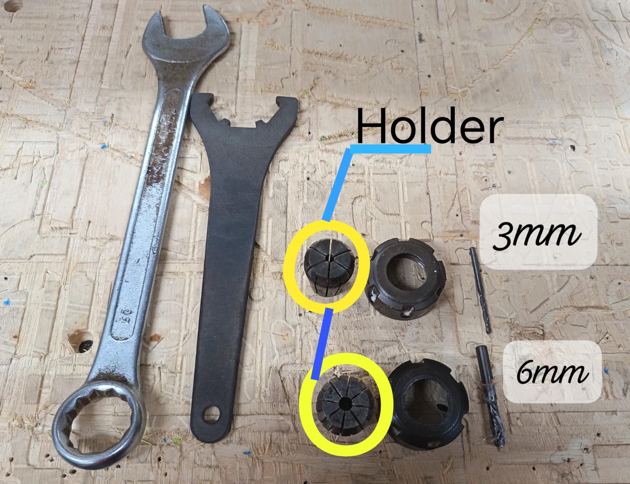
Later, I learned how to prepare the CNC machine by installing the milling tools correctly. Using the wrenches, I adjusted the spindle nut and mounted the collet holder, where the milling bits of 3 mm and 6 mm were placed. This setup was important to guarantee stability and precision during the cutting process.
🤝 Group Assignment Reflection
During the group assignment, I learned the importance of machine calibration, safety procedures, and proper setup when working with computer-controlled machining equipment. Through different tests, we evaluated parameters such as runout, alignment, fixturing methods, cutting speeds, feed rates, toolpaths, and material behavior. These experiments helped me understand how each variable directly affects machining precision, surface finish, and overall fabrication quality. I also realized that correct material fixation and machine alignment are essential to prevent errors, vibrations, or damage during the machining process.
Another important learning outcome was understanding how toolpath strategies and machining parameters influence efficiency and final results. By comparing different configurations and observing the machine operation in real time, I gained a better understanding of subtractive manufacturing workflows and the relationship between digital CAM preparation and physical machining. Working collaboratively also allowed us to share observations, troubleshoot issues together, and reinforce safe practices while operating CNC equipment.
individual Assignment:
° Make (design+mill+assemble) something big
1. Introduction
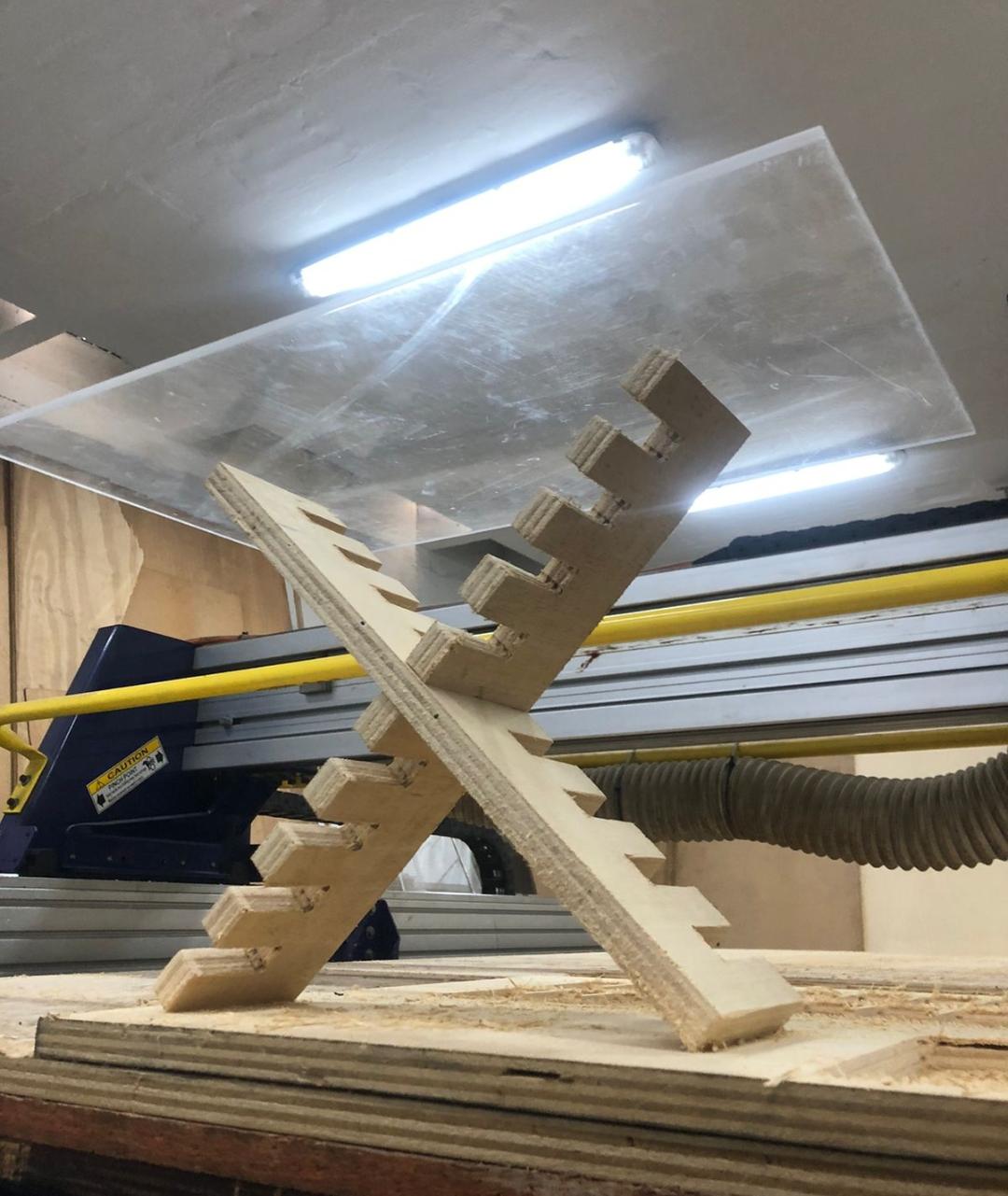
During this week, I learned the process of computer-controlled machining by designing, milling, and assembling a small shelf using a CNC router. The project was made with 18 mm phenolic plywood, starting from the digital design, followed by the milling process, and finally assembling the pieces.
This assignment helped me understand how a digital design can be transformed into a physical object, as well as the importance of proper material preparation, tool selection, and accurate assembly to create a stable and functional structure. 🪵⚙️
📊 2. Furniture Sketch
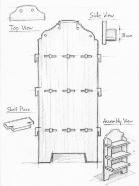
Before starting the machining process, I created a sketch to define the structure and dimensions of the wall shelf made from 18 mm phenolic plywood (triplay). The sketch helped me visualize how the different parts would fit together and plan the joints and screws needed for the assembly.
This initial drawing served as a guide for the digital design and ensured that the pieces were suitable for CNC milling and final assembly. 🪵📐
📈3. 3D Modeling:
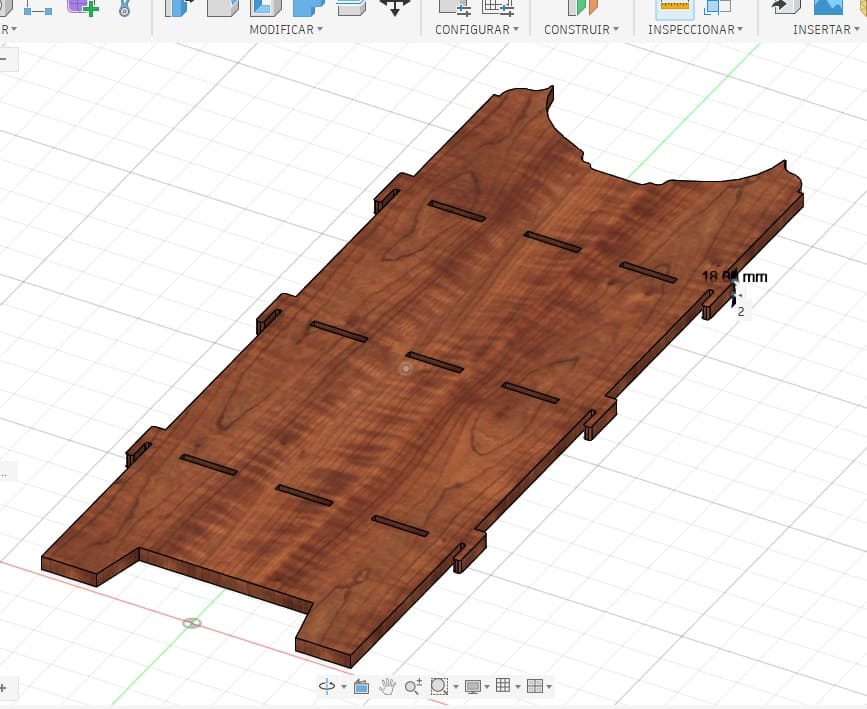
The 3D model of the shelf was designed using Fusion 360, where I created the digital structure of the furniture based on the initial sketch. In this stage, I defined the dimensions of each component considering the 18 mm thickness of the phenolic plywood (triplay) that would be used for fabrication.
Using Fusion 360, I modeled the different parts of the shelf, including the slots and joints that allow the pieces to fit together during assembly. This step was important to verify that all components aligned correctly and that the design was suitable for CNC milling.📐🪵⚙️
⚙️🪵4. 2D Drawings
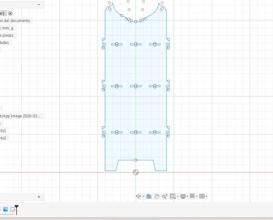
After completing the 3D model in Fusion 360, I created the 2D drawings of each component of the shelf. In this step, the pieces were flattened and arranged to prepare them for the CNC machining process.
The 2D drawings included the outlines of the parts, slots, and joints that allow the pieces to fit together during assembly. This step was important to ensure that all the dimensions were correct and compatible with the 18 mm phenolic plywood (triplay) used in the project.
These 2D files were later used to generate the toolpaths required for the CNC router to cut the pieces accurately. 📐⚙️🪵
⚙️🪵5. Import 2D Plans into PartWorks
After generating the toolpaths, I saved the G-code file and transferred it to the CNC machine. The file was then loaded into the ShopBot3 Router control software, which is used to operate the CNC router.
Through this program, I prepared the machine to start the fabrication process. Once the file was loaded, the CNC machine followed the programmed toolpaths to cut the parts from the phenolic plywood (triplay) accurately, allowing the components of the shelf to be produced for the assembly stage. ⚙️🪵
⚙️🪵5.1 CAM Preparation
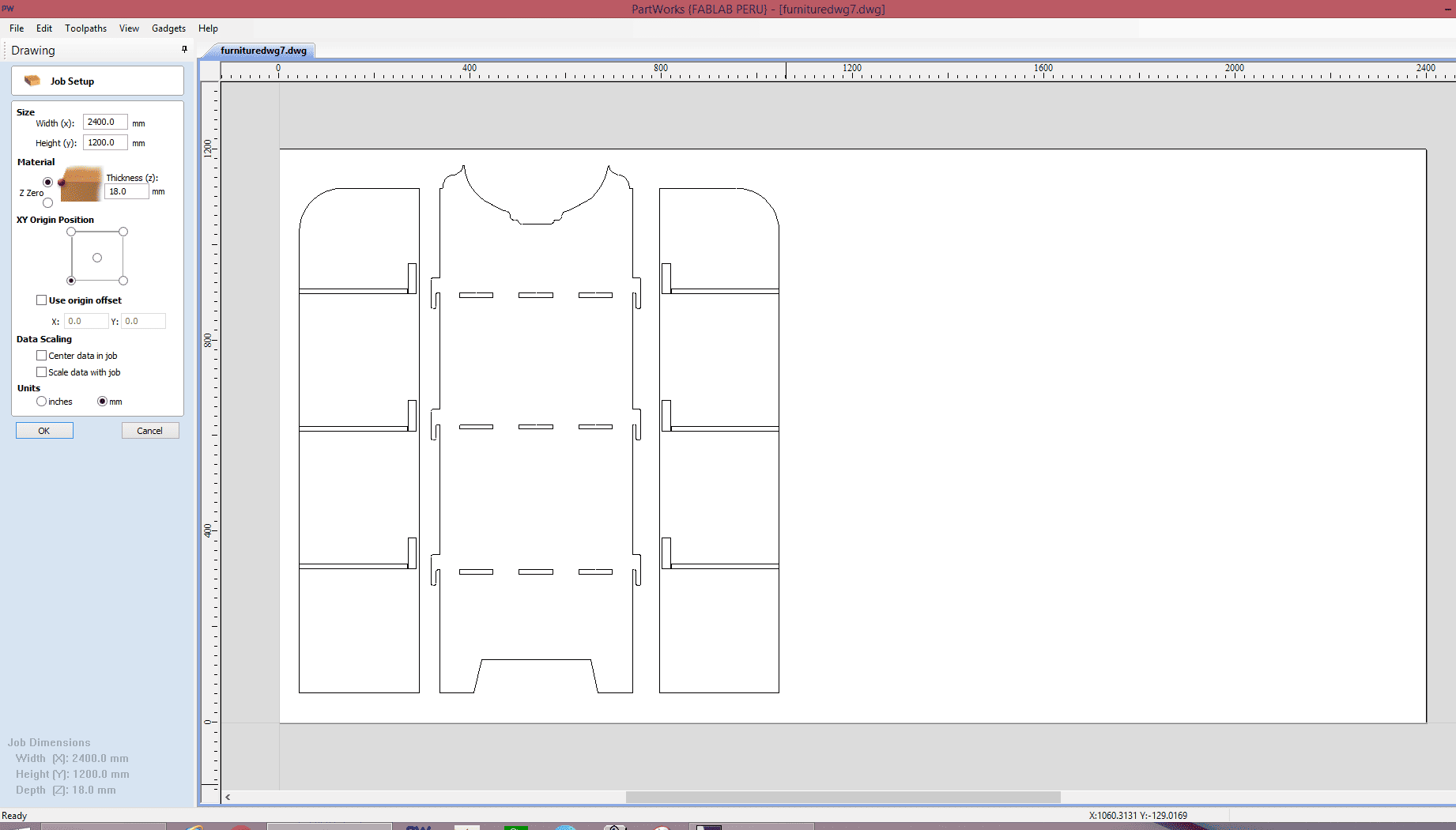
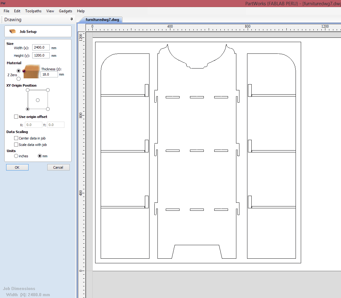
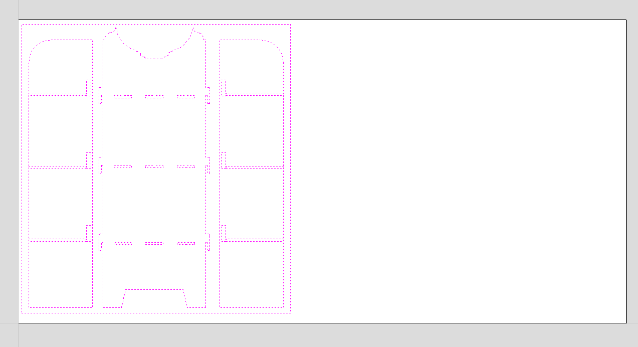
After completing the 2D drawings, I exported the design in DXF format and imported it into PartWorks by ShopBot to begin the CAM preparation process. Once the file was loaded into the software, I configured the workspace according to the real dimensions of the ShopBot PRSalpha 96 CNC machine, allowing me to work at full scale inside the actual machining area. To organize the cutting layout correctly, I placed all the pieces inside a rectangular frame representing the real dimensions of the material sheet that would be machined. This helped me verify that every component fit properly within the available workspace while also optimizing material usage before generating the toolpaths.
⚙️🪵5.1.2 Workspace Configuration
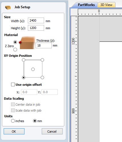
After importing the DXF file into PartWorks, I configured the workspace according to the real working dimensions of the ShopBot PRSalpha 96 CNC machine, which has an approximate cutting area of 1200 mm × 2400 mm. Setting the workspace at the actual machine size allowed me to visualize the project at full scale and ensure that all the furniture components were positioned correctly within the machining area. This configuration step was important to avoid cutting outside the material boundaries and to verify that the entire layout could be machined safely and efficiently before generating the toolpaths.
📏🪵5.1.3 Material Dimensions Setup
To define the material dimensions inside PartWorks, I created a rectangular frame representing the real size of the plywood sheet that would be used during the CNC machining process. This frame served as a visual reference for the material boundaries, allowing me to organize all the furniture components efficiently within the available cutting area. By arranging the pieces carefully inside these limits, I was able to optimize material usage, reduce unnecessary waste, and verify that every part could be machined correctly without exceeding the dimensions of the board.
⚙️🪵5.2 Toolpath Generation
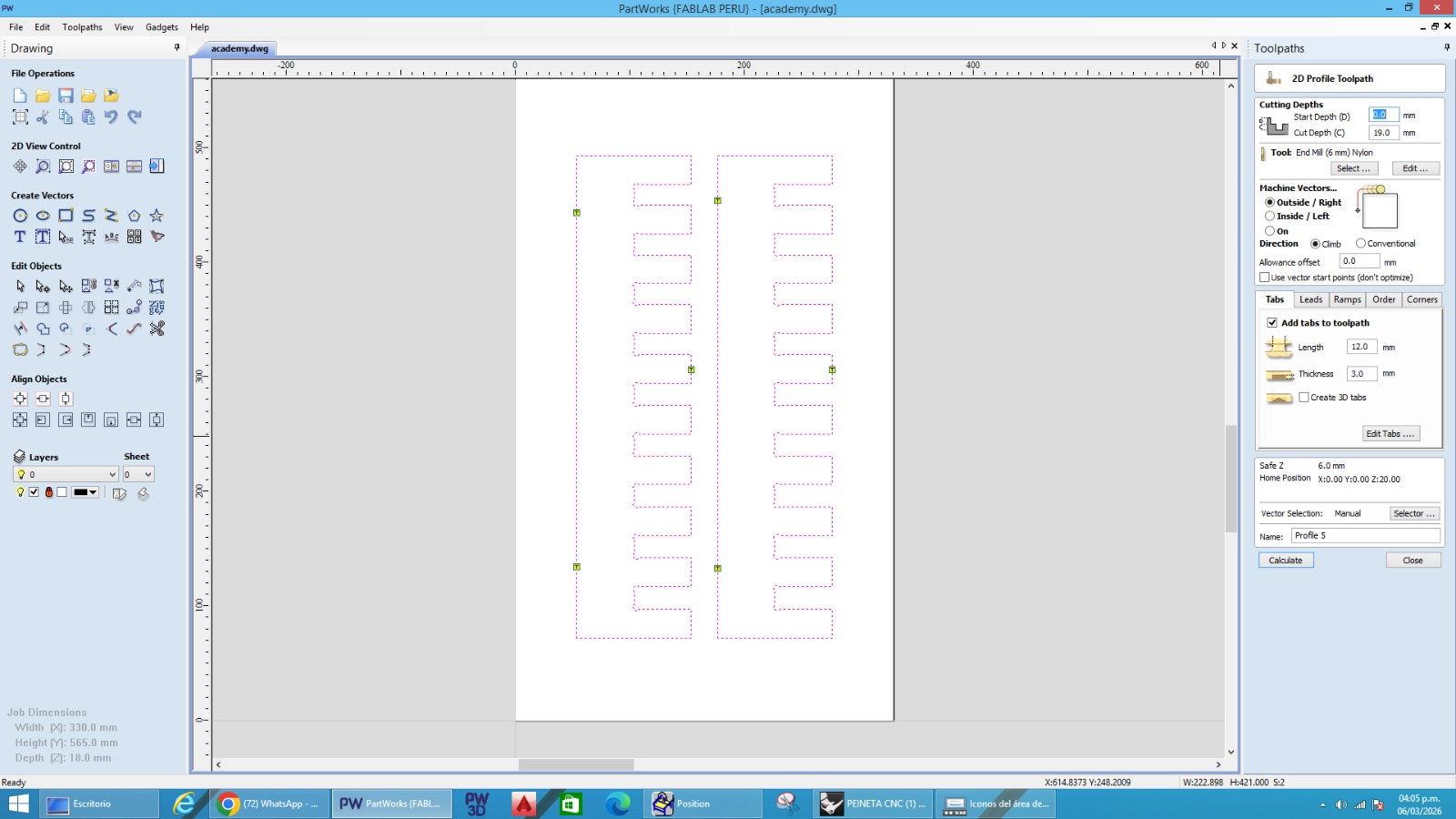
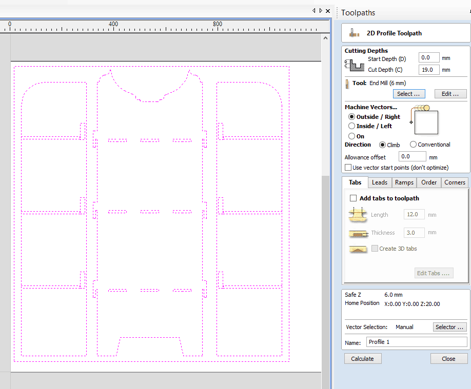
To generate the machining toolpaths in PartWorks, the first step I performed was selecting the vectors corresponding to the external contours of each furniture component. After selecting the vectors, I used the Outside Cut option to ensure that the CNC machine would cut along the outer side of the geometry while maintaining the correct final dimensions of every piece. This operation was essential for obtaining accurate parts that could later fit properly during the assembly process.
During the toolpath configuration, I also enabled the option for automatic tabs, which helped keep the cut pieces attached to the material sheet during machining and prevented them from moving while the CNC router was operating. For the cutting direction, I configured the toolpath using the Right direction, which defined the machining orientation along the selected vectors. Once the parameters and cutting paths were configured, I visually reviewed the generated toolpaths inside the software before continuing with the machining simulation process.
⚙️🪵5.3 CAM Settings
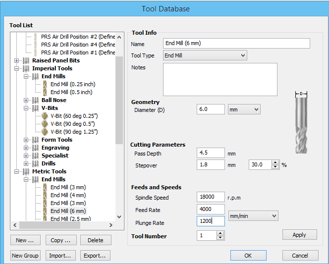
For the CNC machining process, I configured the cutting parameters in PartWorks according to the material properties and the capabilities of the ShopBot PRSalpha 96 machine. I used a feed rate between 4000 and 5000 mm/min, which allowed the machine to maintain a stable cutting movement while achieving efficient material removal. The spindle speed was configured at 18,000 RPM, providing enough rotational speed for clean cuts on both the 18 mm phenolic plywood and the recycled plastic material.
To avoid excessive stress on the tool and improve machining quality, I configured a depth of cut of 4.5 mm per pass, requiring a total of approximately 4 passes to completely cut through the material thickness. Additionally, I used a plunge rate between 1000 and 1500 mm/min to control the vertical entry speed of the tool into the material safely and smoothly. For the cutting strategy, I selected the Climb Cut method because it helps produce cleaner edges, reduces vibration, and improves the surface finish during the CNC machining process.
⚙️🪵5.4 3D Simulation
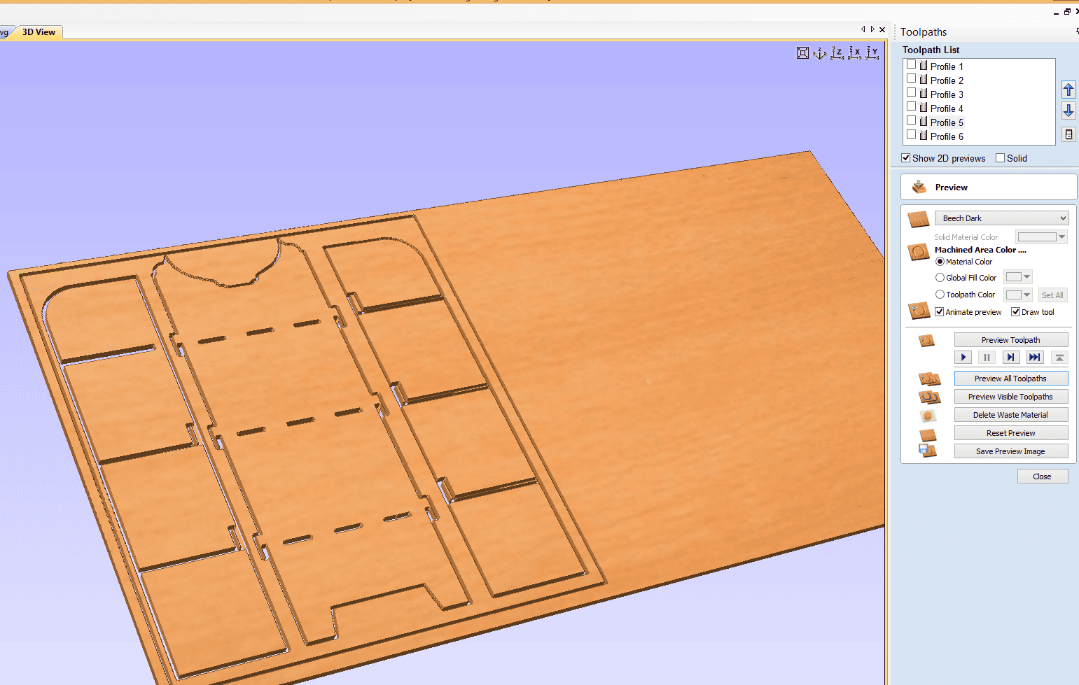
Before generating the final machining file, I performed a complete 3D simulation inside PartWorks to verify that all the toolpaths were configured correctly and that the machining process would run safely on the CNC machine. This simulation allowed me to visualize how the cutting tool would move across the material, including the profile cuts, cutting depth, machining order, and the overall behavior of the CNC process before starting the real machining operation.
The simulation was also useful for checking that all the furniture components were correctly positioned inside the material boundaries and within the working area of the ShopBot PRSalpha 96. Through this preview, I was able to confirm that the toolpaths were cutting in the correct direction, verify the position of the tabs, and ensure that no parts exceeded the available workspace. Performing the 3D simulation before exporting the machining file helped reduce possible machining errors and provided a better understanding of how the final cutting process would be executed.
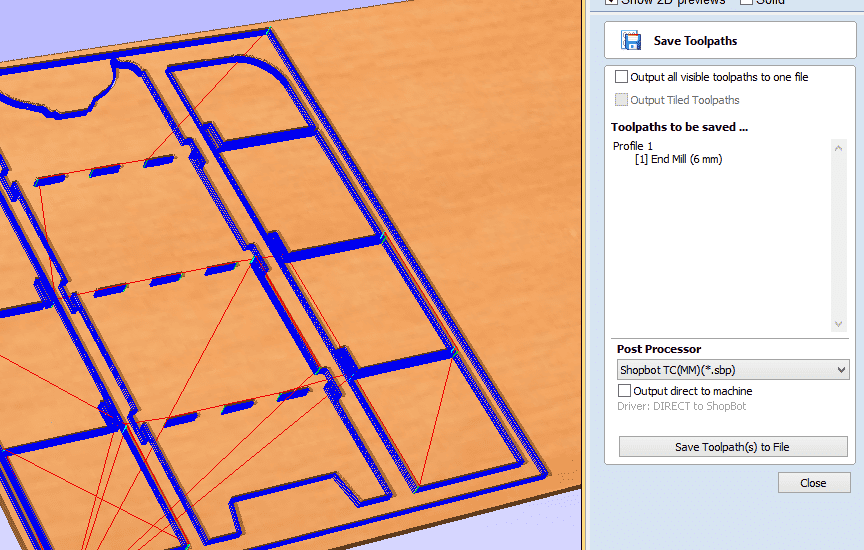
⚙️🪵5.5 G-code Generation
After completing the toolpath configuration and verifying the machining process through the 3D simulation, I proceeded to generate the final machining file in PartWorks. For this project, I exported the file using the ShopBot post-processor, which generated the machining instructions in .SBP format (ShopBot Part File). This file type is specifically designed for ShopBot CNC machines and contains all the commands required for the machining process, including tool movements, cutting paths, spindle activation, feed rates, plunge operations, and machining coordinates.
Once the .sbp file was generated, I transferred it to the ShopBot Control Software to prepare the CNC machine for machining. Before starting the cutting process, I verified the machine setup, checked the material positioning, and configured the machine zero points to ensure proper alignment with the material sheet. Generating the SBP file correctly was an important step because it transformed the CAM configuration into executable machine instructions that allowed the CNC router to reproduce the designed furniture components accurately.
⚙️🪵6. Material Selection:
For this project, I selected 18 mm plywood as the main material for the fabrication of the shelf. This material was chosen because it provides good strength, durability, and stability, making it suitable for furniture structures.
The thickness of 18 mm also allows the pieces to fit properly using slot joints and ensures that the shelf can support weight once assembled. Additionally, plywood is a material that works well with CNC machining, allowing clean and precise cuts during the milling process. 🪵⚙️
⚙️🪵7.Fixing the Material on the CNC Router:
For this project, I selected 18 mm plywood as the main material for the fabrication of the shelf. This material was chosen because it provides good strength, durability, and stability, making it suitable for furniture structures.
The thickness of 18 mm also allows the pieces to fit properly using slot joints and ensures that the shelf can support weight once assembled. Additionally, plywood is a material that works well with CNC machining, allowing clean and precise cuts during the milling process. 🪵⚙️
7.1 Router Tools Used
During the Electronics Design week, we worked with different measurement and programming tools to evaluate and confirm the performance of our electronic board. These tools allowed us to generate and analyze electronic signals to verify that the circuit was functioning properly. Throughout the process, we observed signal waveforms, checked voltage levels, ensured there were no short circuits, and confirmed that the generated signal remained stable.
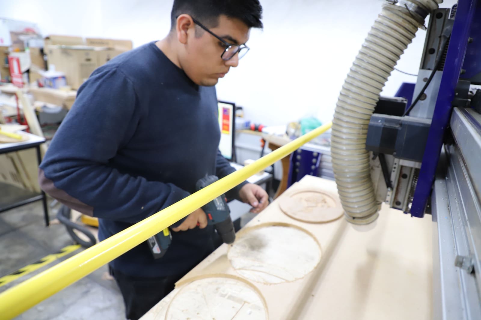
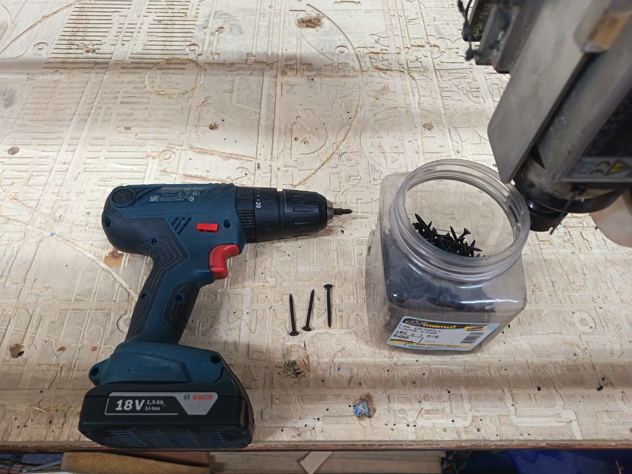
🔫 Cordless Drill / Screwdriver
For the first step of the fabrication process, I used a cordless drill/screwdriver. This tool allowed me to easily drive screws into the wood and securely assemble the structure. Cordless drills are portable power tools powered by rechargeable batteries and are commonly used for drilling holes and driving screws in construction and carpentry tasks. :contentReference[oaicite:0]{index=0}
The drill provided enough torque to quickly fasten the screws and ensure a firm connection between the wooden parts.
🔩 Wood Screws
Wood screws were used to join the structural components of the project. These screws penetrate the wood and create strong mechanical joints that hold the material firmly together.
In woodworking, screws are commonly used together with drills or drivers to assemble wooden parts efficiently and securely. They provide a strong and reliable fastening method for structural assemblies. 🔩
🚪 Phenolic Plywood (18 mm)
The material used for this step was an 18 mm phenolic plywood board. This type of plywood is widely used in digital fabrication and construction due to its strength, durability, and resistance to deformation.
The screws were used together with the drill to securely fix the plywood pieces, ensuring a stable base for the next stages of the project. 📏
7.2 Router Tools Used
During the Electronics Design week, we worked with different measurement and programming tools to evaluate and confirm the performance of our electronic board. These tools allowed us to generate and analyze electronic signals to verify that the circuit was functioning properly. Throughout the process, we observed signal waveforms, checked voltage levels, ensured there were no short circuits, and confirmed that the generated signal remained stable.
🔧 Wrenches for Spindle Adjustment
These wrenches are used to tighten or loosen the spindle nut in order to install or remove the milling bits. Using the correct wrench ensures that the tool holder is properly secured.
- Tool type: Open-end wrench
- Function: Tightening the spindle nut
- Use: CNC tool installation
⚙️ Collet / Tool Holder
The collet (tool holder) is the component that holds the milling bit inside the spindle. It ensures that the bit remains centered and stable during the machining process.
- Component: CNC collet
- Function: Holding the milling bit
- Importance: Precision and stability
🪚 Milling Bits (3mm / 6mm)
Milling bits are the cutting tools used by the CNC machine to remove material. In this process, 3 mm and 6 mm drill bits were used depending on the type of cut and machining requirements.
- Sizes: 3 mm and 6 mm
- Use: Cutting and drilling
- Application: CNC machining
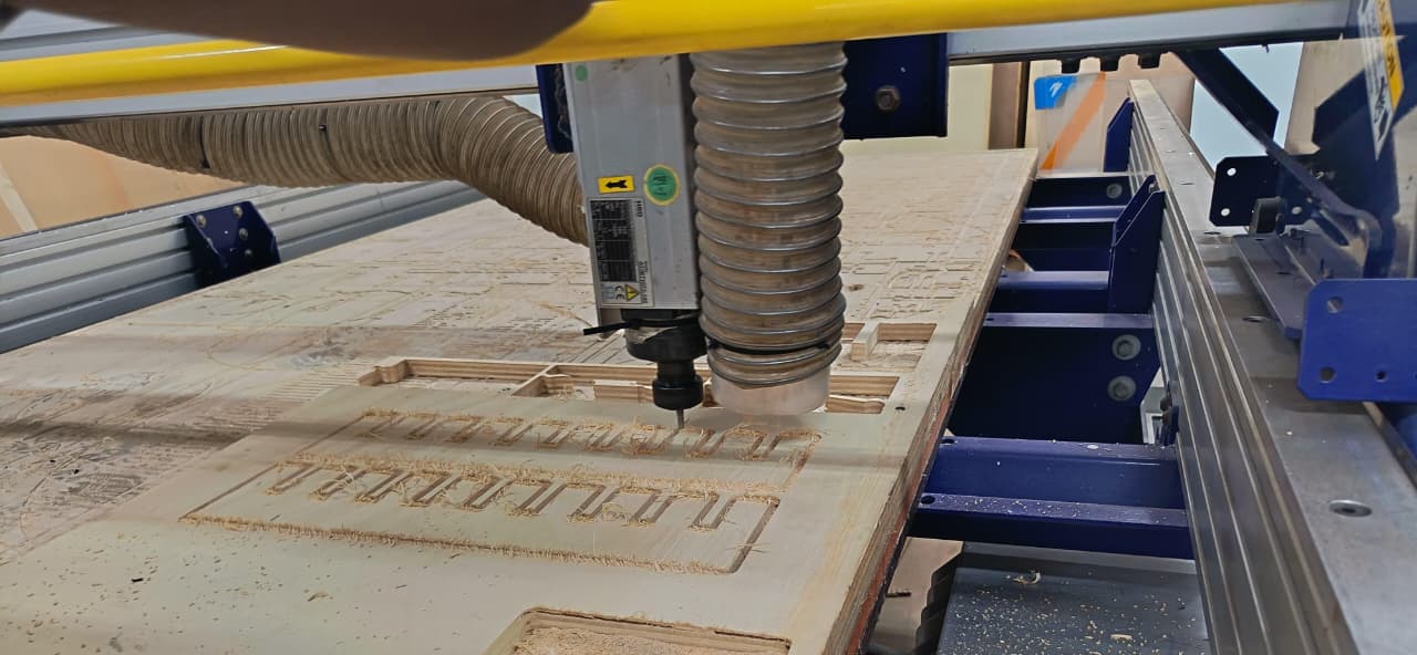
⚙️🪵8. Cutting the Pieces:
During the cutting stage, the CNC machine followed the toolpaths to mill the parts of the shelf from the 18 mm plywood board. Before starting the machining process, I prepared the file in RDWorks, where I added tabs to the design.
These tabs were important because they help keep the pieces attached to the board while the CNC is cutting. This prevents the parts from moving or jumping when the milling bit follows the cutting path, ensuring that the pieces remain stable and the cuts follow the original design accurately. This step helped achieve cleaner and safer machining results. ⚙️🪵
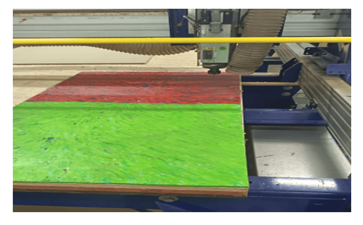
⚙️🪵9. Experimenting with news materials:
As part of the experimentation process, I tested a different material to observe how it behaves during machining. The material I used was a 10 mm board made from pressed recycled plastic bottle caps.
This material allowed me to explore how alternative and recycled materials react to CNC cutting. By machining this board, I could compare its behavior with plywood, observing differences in cutting quality, material resistance, and finishing. This experiment helped me better understand how different materials respond to CNC fabrication processes. ♻️⚙️
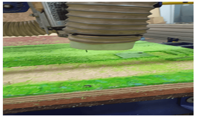
⚙️🪵9.1 Experimenting with news materials:
For this machining test, I experimented with recycled plastic sheets made from compressed bottle caps. Since this material behaves differently from wood or acrylic, selecting the correct cutting tool and machining parameters was very important to avoid melting, excessive burrs, or poor surface finish during the CNC process. For the machining operation, it is recommended to use a flat end mill or single-flute end mill, because these tools help evacuate chips more efficiently and reduce heat accumulation while cutting plastic materials.♻️⚙️
To achieve cleaner cuts, moderate spindle speeds and controlled feed rates are recommended. A spindle speed between approximately 10,000–14,000 RPM combined with a feed rate around 800–1500 mm/min can help maintain stable cutting performance depending on the thickness and density of the recycled plastic sheet. It is also important to use shallow cutting depths per pass and ensure proper chip evacuation to minimize overheating and deformation of the material. Through this experiment, I learned how machining parameters must be adapted according to the physical properties of non-traditional recycled materials.
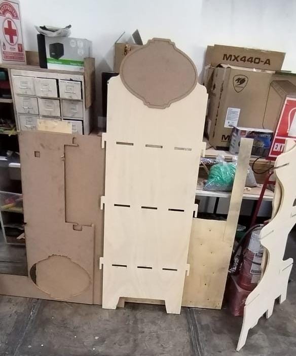
⚙️🪵10. Sanding and Assembly:
After the CNC machining process was completed, I removed the pieces from the plywood board and cleaned the edges where the tabs were located. Then, I sanded the surfaces and edges to eliminate small imperfections and obtain a smoother finish.
Once the sanding process was finished, I proceeded with the assembly of the shelf, fitting the pieces together according to the design. To reinforce the structure and ensure stability, I used wood screws and a drill/driver to securely fix the components. This final step allowed me to complete the wall shelf (repisero) and verify that all the parts fit correctly. 🪵🔧⚙️
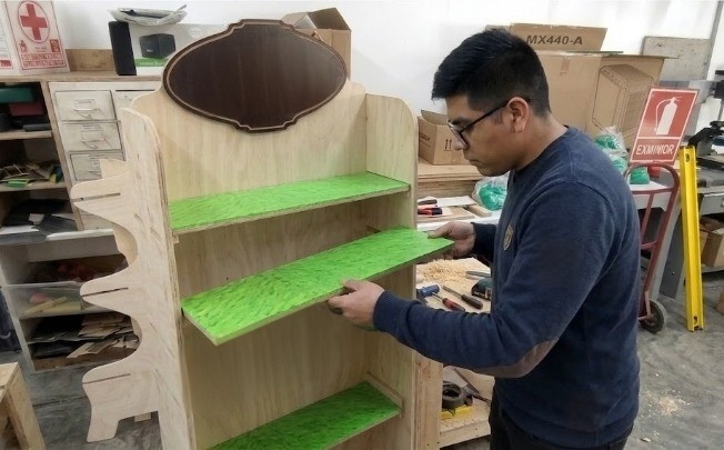
⚙️🪵 Sanding and Assembly:
After machining all the wooden parts on the CNC machine, I proceeded with the assembly process of the furniture structure. In this stage, I carefully aligned each shelf and side panel to ensure proper fitting and structural stability. As shown in the image, I manually inserted the shelves into their designated slots, verifying that the dimensions obtained from the digital design matched correctly with the machined pieces. The press-fit style assembly helped reduce movement between components and provided a firm structure without requiring complex fastening systems.
During the assembly process, I also checked the alignment of the shelves and the perpendicularity of the entire structure to maintain a clean and professional appearance. The green shelf surfaces added contrast to the wood finish and helped visualize the final aesthetic result of the project. This stage allowed me to validate the precision of the CNC machining process and understand the importance of tolerances and fit adjustments in large-scale digital fabrication projects.
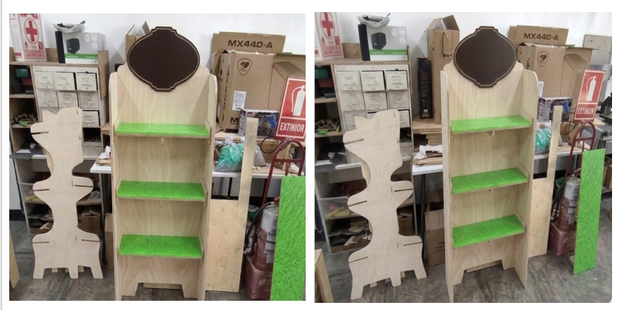
⚙️🪵11. Final Result
The final result of the project was a fully assembled CNC-machined furniture piece with a functional and visually attractive design. After completing the machining and assembly processes, all the components fit correctly, demonstrating good precision in the digital design and fabrication stages. The structure was stable, and the shelves aligned properly with the side panels, confirming that the tolerances used during the CAD and CAM preparation were adequate for the material and machining process
The combination of the wood finish with the green shelf surfaces provided a more dynamic and modern appearance to the final piece. Additionally, the decorative upper sign and the custom side profile helped give the furniture a more personalized identity instead of a simple standard shelf. This project allowed me to better understand the complete workflow of computer-controlled machining, from digital design and toolpath preparation to CNC machining, assembly, and final presentation of the manufactured object.
⚙️🪵12. Individual Reflection
During this assignment, I learned the complete workflow involved in computer-controlled machining, from preparing the digital design to assembling the final furniture piece. One of the most important things I learned was how critical it is to correctly define toolpaths, machining parameters, tolerances, and material fixation before starting the CNC process, since small mistakes can directly affect the final assembly. I also gained more experience working with large-format machining compared to smaller digital fabrication processes like 3D printing or laser cutting.
Another important learning outcome was understanding how different materials behave during machining and how feed rates, spindle speed, and tool selection influence the surface finish and cutting quality. The assembly stage also helped me realize the importance of precision in CAD design because every slot and joint must match correctly for the structure to fit properly. Overall, this assignment improved my confidence in using CNC machines and strengthened my understanding of subtractive manufacturing processes within digital fabrication workflows.
Files
Here are the project files available for download:
- Peineta: Download .dxf
- Design en Fusion 3D and 2D model: Download .f3d
- Design in Rhinosceros: Download .3dm
- Design in CAD: Download .dwg