System Integration
weekly schedule.
| Time block | Wed | Thu | Fri | Sat | Sun | Mon | Tue | Wed |
|---|---|---|---|---|---|---|---|---|
| Global class | 3 h | |||||||
| Local class | 1.5 h | |||||||
| Research | 1 h | 2 h | 1 h | 3 h | ||||
| Design | 4 h | 2 h | ||||||
| Fabrication | 2 h | 2 h | 1 h | |||||
| Documentation | 3 h | |||||||
| Review |
overview.
This week is about stepping back. System integration is a different exercise from everything I have done so far in Fab Academy — it asks you to pull back from individual parts (PCBs, motors, tubes) and look at how the whole thing comes together as a product.
The honest truth is that I arrive at this week without the project maturity I would want for it. A combination of work load, family life, and, frankly, imperfect time management, has meant that I am still carrying open assignments from previous weeks, and I have not had the calendar space to let the project design settle to the point where system integration would feel like a natural next step. So this page is not the integration of a mature, fabricated system — it is the plan for that integration, drawn while I am still actively designing and fabricating the parts it is supposed to integrate.
I would rather document it that way than pretend otherwise. The diagrams, BOM, failure-mode analysis and schedule below are real work and they will inform what I actually build in the next four weeks — but the reader should know that a lot of what is shown here is still ahead of me, not behind me.
learning objectives.
- Define what “system” means for my standing desk, not just “list of parts”
- Draw a block diagram that an outsider can read
- Make a BOM I can actually buy from
- Identify the failure modes I am most exposed to
- Be honest about what is missing and what is next
assignments.
Individual
- Make a plan for system integration of the final project
- Document it with CAD and/or sketches
- Implement methods of packaging
- Design the project to look like a finished product
- Document system integration
- Link from the final project page
what is a “system” for my desk.
Before drawing anything, I tried to write in one sentence what my project is, as a system and not as parts:
A 4-leg standing desk where one central touchscreen tells four identical legs to go to a target height, each leg measures its own distance to the floor, and they coordinate so the tabletop stays level.
From that one sentence I can pull out the actors:
- One master (touchscreen + brain)
- Four legs, each one identical
- A shared physical structure (tabletop) that constrains them
- A shared power supply
- A communication bus between master and legs
- A user (me, my body, my back)
That is the level of abstraction I want for the block diagram. Components come later.
user flow.
Before drawing the electronic system, I sketched what the user sees. The desk is a piece of furniture first and a piece of electronics second — if the interaction with the touchscreen is wrong, none of the engineering underneath matters. This is the flow I designed in Excalidraw and it informed every other diagram on this page (in particular, the convergence point in the middle of the flow tells me there is exactly one place in the code where commands fan out to the four legs, which is the Master sends target block).
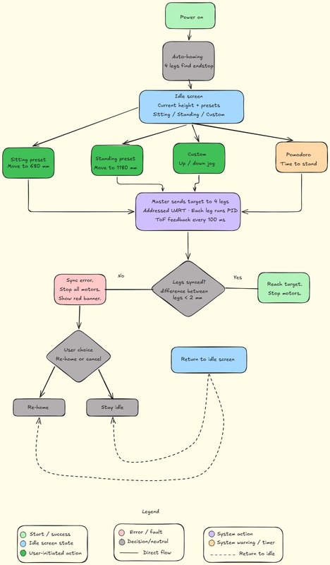
One thing the flow assumes but does not draw as a button: there is no separate power switch. The desk has no on/off control of its own — plugging the PSU into the wall socket is turning it on. As soon as it has mains power the master boots, the four legs home automatically, and the up/down buttons are immediately live for height adjustment. Unplugging it from the wall is the only “off”. I kept it this way on purpose — a standing desk should behave like a lamp, not like a computer you have to boot — but it is worth stating explicitly, because the diagram starts at “power on” and a reader could otherwise ask where that comes from.
Three things this diagram made explicit that I had not written down before:
- Single convergence point. All four user actions (two presets, custom jog, Pomodoro) end up calling the same routine on the master. That is one function in the firmware, not four — which simplifies testing.
- The sync check is the only safety gate. If the four legs drift apart by more than 2 mm during motion, everything stops. There is no “graceful degradation” path; the user has to acknowledge before the system tries again.
- Two paths back to idle. The happy path (success) and the recovery path (re-home or cancel) both return to the same idle screen. That keeps the user model simple — there is one “home” state, not a tree of nested screens.
block diagram.
This diagram describes the final project, not the proof of concept. Where the PoC has to deviate (mostly the driver and the lead screw), I will say so explicitly.
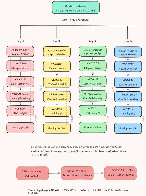
A few things worth calling out in the diagram:
- Master ↔ legs: addressed UART. One bus, every XIAO listens; the master prefixes each command with the target leg address. This is what the network week landed on.
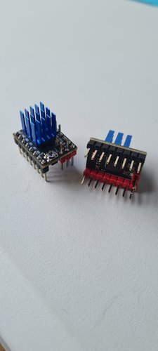
- Driver: TMC2209 SilentStepStick in both the final design and the PoC currently on my bench. The A4950 dual H-bridge I designed in Week 10 stays as a backup option but the integration work is happening on TMC2209 because that is the actual driver of the final product.
- Sensor: VL53L1X ToF, one per leg, living in the external
electronics_boxunder the tabletop and pointing down to the floor. Direct measurement of table height, not a stepper-counting estimate. - Power topology: 230 VAC → PSU 24 V / 8 A → motor drivers in parallel + a DC-DC 24-to-5 V for the master and the four XIAOs. One PSU, two rails, single ground reference at the PSU.
wiring map (rough).
I sketched the topology on paper at the lab while listening to Neil, then turned that sketch into the clean diagram below. The point is not to be a schematic — it is to show what cable goes where and what the failure modes are along each cable.
Top-down wiring map of a 4-leg standing desk seen from under the tabletop. One central master (ESP32-S3 + LCD) linked to four corner electronics_boxes (XIAO + TMC2209 + ToF) over a dashed addressed-UART bus; each box drives its own motor with a short solid 4-wire cable; a 24V/8A PSU feeds a 24V motor rail and a DC-DC 24→5V logic rail, drawn as dashed power lines forming a single ground star at the PSU. Flat schematic style, soft colours, a legend at the bottom.
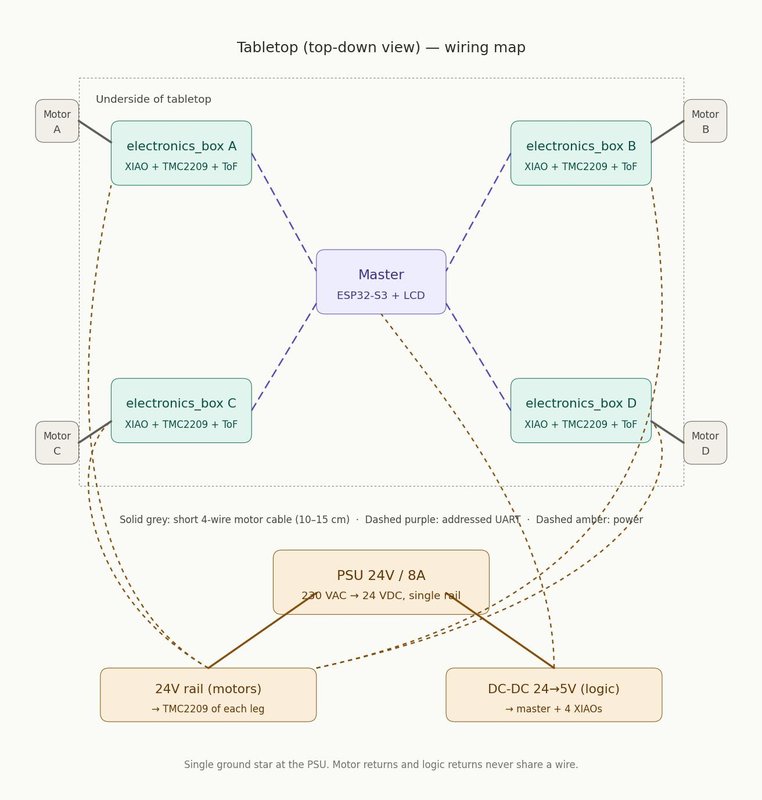
Key decisions visible in the map:
- Short motor cables. The driver lives 10–15 cm from the motor, not next to the master. This minimises noise on the high-current path and keeps the long bus low-voltage and low-current — exactly the “ground mecca” pattern Neil described.
- Single 24V star from the PSU. Each leg gets its own pair from the PSU output terminal block, not daisy-chained. Daisy-chained power means that when leg D pulls peak current, the voltage drop across the wire to leg D also pulls down legs A, B and C downstream of the same branch — a star topology makes every leg see the same supply voltage regardless of what the others are doing.
- Addressed UART bus. One pair for data + a separate pair for power + ground. UART is enough for cable runs around 1.5 m diagonally; if I hit noise problems during integration I can swap the transceivers for RS485 without changing the topology.
what the final leg looks like.
The block diagram above is the electronic system. This figure is the mechanical side of the same final design — one leg, fully extended (1280 mm, standing position), annotated.
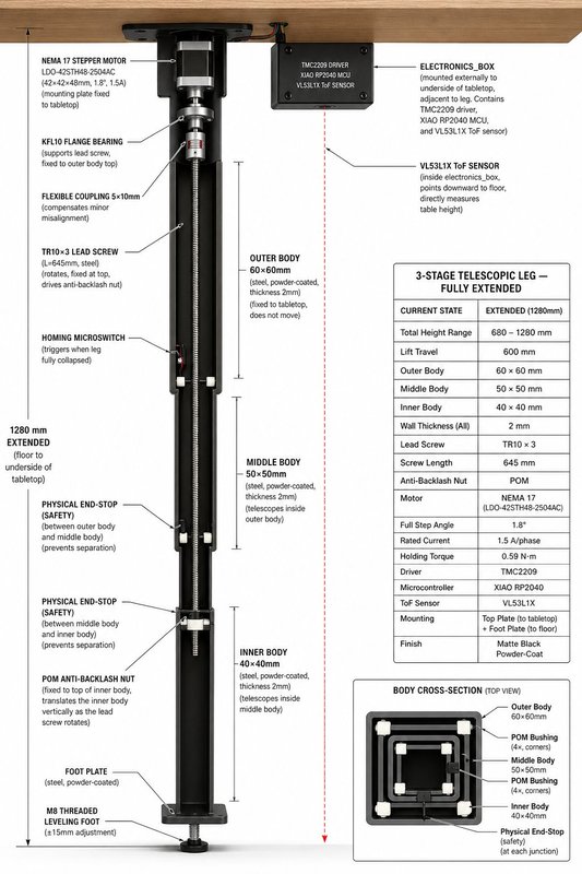
Reading the figure together with the block diagram, the integration logic of one leg becomes:
- The tabletop anchors the outer body (60×60 mm steel tube, fixed, does not move) and carries the electronics_box on its underside.
- The NEMA 17 motor sits at the top of the leg, hanging from the top plate. Its shaft connects through a flexible coupling to the TR10×3 lead screw.
- The lead screw rotates in the KFL10 flange bearing and drives the POM anti-backlash nut.
- The anti-backlash nut is fixed to the top of the inner body — so as the screw rotates, the inner body translates vertically.
- The middle body is dragged along by physical end-stops at the body junctions, which also prevent the bodies separating at full extension.
- The homing microswitch at the top of the outer body triggers when the leg is fully collapsed (sitting position, 680 mm).
- The VL53L1X measures absolute table-to-floor distance — true height feedback, not estimated from step counts.
This figure is not a fabrication drawing — the source of truth is the Fusion 360 model. But it is the cleanest single image I have of the integration target, and it pairs naturally with the block diagram: one tells you the electronic topology, the other tells you where every part physically lives.
The illustration itself was generated with ChatGPT and then checked part by part against my own spec — it is a communication aid, not a measured drawing.
Engineering cutaway of one fully-extended telescopic standing-desk leg, vertical. Three nested square steel tubes (60/50/40 mm, matte black powder-coat), NEMA 17 at the top hanging from a top plate under a wood tabletop, flexible coupling to a TR10×3 lead screw, KFL10 flange bearing, POM anti-backlash nut fixed to the top of the inner body, POM bushings and physical end-stops at each junction, homing microswitch, foot plate with M8 leveling foot. External electronics_box under the tabletop next to the leg with a downward-pointing ToF sensor. Left-side line callouts naming each part plus a spec data panel on the right. Clean technical-illustration style, neutral background.
proof-of-concept deviations.
What I am building this week and next is the PoC. It differs from the figure above in a few specific places, all driven by what is available in the lab and what is reasonable to validate at this stage:
| Element | Final design | PoC track |
|---|---|---|
| Body material | 60/50/40 mm steel tubes, powder-coated | PVC pipes DN50 / DN40 / DN32 |
| Lead screw | TR10×3 (self-locking) | TR8×8 (fast, not self-locking) |
| Driver | TMC2209 SilentStepStick | TMC2209 SilentStepStick (same) |
| ToF sensor | VL53L1X | VL53L0X (acceptable for short range) |
| Motor | LDO-42STH48-2504AH (Class H, 2.5 A/phase, 55 N·cm) | Usongshine 17HS4023 (1.0 A/phase, 13 N·cm) |
| Power | PSU 24V/8A | Bench PSU (Hanmatek) at 12 V for validation |
The driver is the same chip in both tracks — that was important to me because I wanted the PoC firmware to be reusable on the final hardware. What differs is the mechanical envelope, the lead-screw geometry, the sensor range, and the motor torque class.
The PoC motor (Usongshine 17HS4023, 13 N·cm) is what the Fab Lab León had available, and that is what I am using to validate the kinematics. It is a much weaker motor than the LDO-42STH48-2504AH (55 N·cm) I plan for the final, so under full tabletop load it would stall. For the PoC this is acceptable — the goal is to validate the integration loop (master → driver → motor → screw → ToF) end-to-end, not to lift 25 kg per leg. The final design is sized around the LDO motor, with a 4× safety margin on torque.
design for manufacturing — bearing seat.
One of Neil’s points stuck with me more than the others: “DFM is designing around the processes you’ll be making.” The implication is that you cannot calculate a tight tolerance from a datasheet on an FDM printer — you have to test it.
The 608ZZ bearing nominally has a 22 mm outer diameter, but the actual press-fit hole depends on the printer, filament, slicer, layer height, cooling and dozens of other variables. So instead of guessing, I printed a test piece with four candidate holes at 22.00 / 22.10 / 22.20 / 22.30 mm and tried the bearing in each.
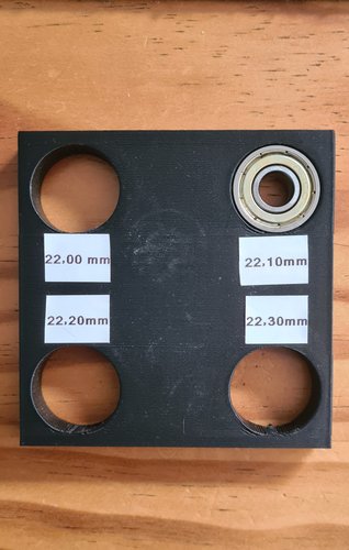
Result: 22.00 mm refused the bearing, 22.20 and 22.30 mm were loose. 22.10 mm gave a firm press fit that holds the bearing without forcing the print. That is the diameter that goes into the final motor-mount and bearing-seat parts of the leg.
This is a tiny test, ten minutes of print time, but it is exactly the kind of thing that prevents a project from failing at the last moment because “the bearing falls out when you move the leg.” DFM and integration are not separate — getting one critical fit right is part of system integration.
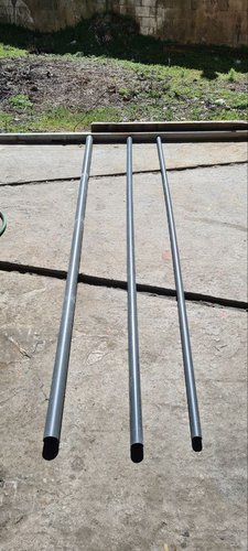
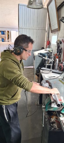
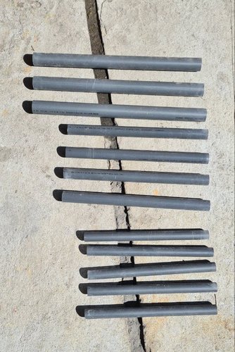
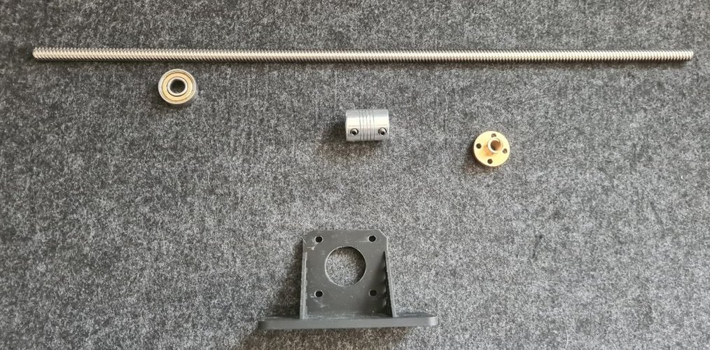
what I have actually built so far.
The mechanical side of the PoC. Three PVC pipes (DN50 / DN40 / DN32) bought from the local hardware store, cut to length with an angle grinder, then deburred. The full leg also needs a motor, a TR8×8 lead screw, a flexible coupling, bearings, an endstop and a 3D-printed motor mount — all of those parts are already on the bench, see the components shot below.
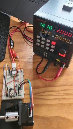
The electronic side of the PoC is further along than the mechanical side, because I have been bench-testing the leg control loop in parallel with cutting tubes:
What is not yet built:
- The full assembled leg with motor, lead screw and PVC tubes mounted together as one telescopic unit
- The PETG-HF-printed electronics_box that holds the XIAO + driver + sensor for one leg in a strain-relieved enclosure (the PETG-HF spool arrived today; all current printed parts are PLA)
- The master node (Waveshare ESP32-S3 with an LVGL UI)
- The wiring harness with proper strain relief and cable management
So the current state is: one leg’s worth of electronics integration working on a breadboard, one leg’s worth of mechanical parts cut and ready, and a clear path to put them together. The pieces have been validated independently — system integration is exactly the step I am writing this week’s page to plan.
bill of materials (one leg, PoC track).
| Item | Qty | Source | Notes |
|---|---|---|---|
| NEMA 17 stepper, Usongshine 17HS4023 | 1 | Fab Lab León inventory | 1.0 A/phase, 13 N·cm, 42×42×23 mm, shaft Ø 5 mm. Provided by the lab |
| TMC2209 SilentStepStick | 1 | HTA3D | Same driver as final design — firmware reuse |
| XIAO RP2040 | 1 | Seeed Studio | Leg controller |
| VL53L0X breakout | 1 | BricoGeek | I²C ToF sensor |
| TR8x8 lead screw, 400 mm | 1 | HTA3D | Fast lead, not self-locking — PoC only |
| Flexible coupling 5x8 | 1 | HTA3D | Motor shaft to lead screw |
| 608ZZ bearing | 1 | HTA3D | Lead screw support at the top |
| TR8 brass nut | 1 | HTA3D | Lead screw follower fixed to inner body |
| 3D-printed motor mount | 1 | self-printed (PLA) | Interfaces NEMA 17 to outer body (will move to PETG-HF for final parts) |
| Endstop microswitch | 1 | BricoGeek | Homing position |
| PVC DN50 / DN40 / DN32 tubes | 1 each | local hardware store | Telescopic bodies |
| Wiring (12-24V, UART) | as needed | RS Online España | Twisted pair for the bus |
For the final track the BOM changes in five places — TR10×3 self-locking lead screw, LDO-42STH48-2504AH motor from Zen3d.eu (55 N·cm, 4× the PoC motor torque), VL53L1X from Pololu, and steel tubes instead of PVC. The driver stays the same TMC2209, which is what allowed me to bench-test the control loop now and reuse the firmware later.
failure modes I am most exposed to.
Going through Neil’s tour of failures and applying it to my own project, I see four that are likely to bite me:
- Brownouts under stepper load. The TMC2209 setup on my breadboard works fine unloaded, but I have not yet measured the 5 V rail under stepper load with a scope. If the XIAO resets when the motor pulls peak current under tension, I will not even know it is resetting unless I look. Action: scope the supply rail while running the leg against a known load, add bulk capacitance close to the XIAO if needed.
- Cable management on a 600 mm stroke. Cables that travel up and down every time the desk moves will rub. Neil’s Apollo / passenger plane example is the extreme version of this. Action: route cables through a flat cable carrier or spiral wrap, never let them run free against the inside of a tube.
- Ground loops between leg current return and logic ground. With four motors potentially drawing 1.5 A each and 4 separate XIAO nodes, the temptation to share grounds opportunistically is high. Action: enforce ground mecca topology in the wiring harness — each leg has its own power return to the PSU, and logic ground is referenced once.
- Component obsolescence. Neil’s example of TI motor controllers disappearing is exactly the risk of designing around the TMC2209 / VL53L1X stack. Action: for the final track, prefer parts that are stocked at multiple EU distributors (RS, Mouser, Digi-Key) rather than one Asian-only source. Keep the A4950 design from Week 10 around as a fallback driver — it is fabricable in-lab if a supply chain shock hits.
what I would change if I had another week.
- Build one full leg end-to-end (PVC + motor + driver + sensor + endstop + cable harness) and shake-test it
- 3D print the electronics box and mount the PCB inside, then drop it from 30 cm to see if anything falls off
- Burn-in: move the leg up and down 200 times under load, measure if anything heats up or loosens
These are next week’s tasks. I am writing them down here so I do not forget.
reflections.
The uncomfortable lesson Neil’s class hammered home is that I had been doing subsystem engineering and assuming integration would just happen at the end. Week by week I built one block — a board, a sensor adapter, a motor driver — and treated “putting them together” as a future problem. The whole point of having a dedicated System Integration class is that this assumption is exactly how final projects fail at the presentation.
The good news is that I had already started taking the integration step before the class hit, almost without noticing. The bench test with the XIAO + TMC2209 + NEMA 17 + lead screw is one leg’s electronics integrated as a working loop, even if it lives on a breadboard and is powered by a lab supply at the wrong voltage. The bad news is that the mechanical side (PVC tubes, motor mount, lead-screw bearing, endstop, cable routing) is still loose parts, and that the inter-leg integration (UART bus, master, synchronisation, ground topology) exists only as block diagrams and a wiring map.
The other thing I underestimated is how much of system integration is documentation. The block diagram, the wiring map, the BOM, the failure-mode list — these did not exist before I sat down to write this week’s page. Just by drawing them I noticed three things I had been quietly planning to do wrong: putting the electronics_box inside the leg, sharing the motor return ground with the logic ground, and routing cables straight along the inside of the tube where they would rub on every stroke.
Honest assessment: this is more plan than finished hardware, and that is fine for week 15 — the final project deadline is the test, not this document. The drop and shake tests will be the actual judges of whether the integration plan written here survives contact with reality.
schedule to defense.
System integration without a schedule is just a wishlist. The Final Project defence is on 8 June, so I have 33 days from the day of this class to deliver a working desk — or at least one defendable leg. The Gantt below is interactive: hover any bar to see start, end and progress; the red bars are the critical path, the orange ones are stretch goals that only get done if the critical path finishes on time.
Reading the chart, the message is uncomfortable: the critical path runs design → board fabrication → one assembled leg, and it eats almost every working day until 28 May. I marked three milestones (diamonds) so the schedule reads as a sequence of provable states, not just a wall of bars: design frozen (the Fusion model and brackets are locked), leg controller board fabricated (the milled-and-soldered PCB exists, not just a breadboard), and the big one, one leg fully working — a single leg that homes, runs the full 600 mm stroke under load and reads its own height. That last milestone is the real proof of the project: if one leg works end to end, the other three are replication, not invention. Everything after 28 May (legs 2-4, master UI, synchronisation) is stretch — if the critical path slips by more than two days the four-leg synchronised demo is at risk and the defence reverts to “one leg, fully working, plus the design of the other three”. That is still a defendable outcome, and it is exactly why “one leg fully working” is the milestone I am protecting.
design files.
No downloadable design files for this week — the diagrams above are derived from the Fusion 360 model (final design figure) and the system-level documentation. The Fusion model and KiCad files for the leg controller will live under the final project page.
link from the final project page.
The system integration work documented here is part of the final project. From this page back to the project, two natural entry points:
- Final project proposal — the original concept, scope and motivation
- Final project development — the rolling log of progress towards 8 June, where this week’s plan lives
The reverse link (from the development page back to this week) is already in the development log timeline under entry “Week 15 — system integration”.
references.
- Neil’s class — System Integration
- Evaluation rubric
- Namita Aravind, Fab Lab Kochi 2025 — Week 15 (structure reference for this page)
- Mauro Herrero, Fab Lab León 2021 — Final project (local reference for system integration of a complex final project)
- Poka-yoke (Wikipedia) — design principle to make wrong assembly impossible, brought up in the chat by myself during the class
- Flyback diode (Wikipedia) — for the inductive kickback discussion
- FMEA — Failure mode and effects analysis (Wikipedia)