Interface and Application Programming.
weekly schedule.
| Time block | Wed | Thu | Fri | Sat | Sun | Mon | Tue | Wed |
|---|---|---|---|---|---|---|---|---|
| Global class | 3 h | |||||||
| Local class | 1.5 h | |||||||
| Research | 1 h | 1 h | 3 h | |||||
| Design | ||||||||
| Fabrication | ||||||||
| Documentation | 3 h | |||||||
| Review |
overview.
This week is about how a user talks to the boards we have been making. Until now everything runs on the microcontroller — we read sensors, blink LEDs, send UART frames between nodes. Starting now, we add a layer on top: an application running on a desktop, a phone or a browser that lets a person see what the board is doing and tell it what to do.
For my final project (height-adjustable standing desk), the long-term user interface will live on the master controller — either a touchscreen or a simpler set of physical buttons, that decision is still open. Either way, building that interface is closed scope for this week. Trying to build the final UI here would mix two big problems: the application logic (what the user does) and the embedded UI framework. I am keeping them separate. Week 14 is the application logic spiral; the embedded UI implementation moves to System Integration.
For this first spiral I am using my XIAO RP2040 Fab board (the one with a button and an LED already routed) because it is the simplest possible “input + output” device I can interface to. The XIAO sits on a header socket, so if I need wireless later I can swap it for an ESP32-S3 without touching the PCB.
learning objectives.
- Understand the difference between embedded code (runs on the MCU) and application code (runs on a host).
- Pick a tool from the broad menu Neil presented (compiled/interpreted languages, low-code dataflow, AI-assisted code) and justify why it fits this case.
- Implement a working bidirectional UI: a button on the board sends an event up to the application, and a button in the application sends a command down to the board.
- Document the tool comparison required for the group assignment.
assignments.
Group assignment:
- Compare as many interface tool options as possible.
- Document the comparison on the group work page and reflect on what we learned.
- Link to the group assignment page.
Individual assignment:
- Write an application for an embedded board I made that interfaces a user with an input and/or output device.
- Document the UI and how I built it.
- Document how the application communicates with the microcontroller.
- Include source code (or a screenshot if not possible).
- Include a hero shot of the running application + board.
class notes — Neil’s lecture (2026-04-29).
These are the points I want to keep handy for the rest of the year, not just for this week.
the question Neil opens with.
What language are you going to use to write the application?
This is a deliberate fork. The class page lists 80+ options. He covers them in three buckets:
| Bucket | Examples | When |
|---|---|---|
| Compiled, low-level | C, C++, Rust, Go | Performance-critical, embedded, system tools |
| Interpreted, dynamic | Python, JavaScript/Node, Ruby | Most application work, fast iteration |
| Low-code / dataflow | Node-RED, mods, Scratch, App Inventor | Wiring devices and UIs together without writing code |
Neil’s recommendations (paraphrased):
- Everyone should learn Python as a general-purpose language.
- Processing is the friendly path coming from the Arduino IDE — same lineage (Processing → Wiring → Arduino).
- JavaScript for anything web-based, because the V8 JIT makes it nearly as fast as C and it runs in every browser.
- For visual data flow, he demonstrated Node-RED (originally from IBM) controlling an ESP32 over WebSockets.
WebSockets, briefly.
I want to use this week to actually understand WebSockets — I have used them as a black box in other contexts but I have never sat down to figure out why the browser allows them when it does not allow raw TCP sockets. So this section is partly notes for me.
Web pages cannot open arbitrary network sockets — that would let any random page open a TCP connection to any port on the local network and either attack internal services or use the user’s browser to launch denial-of-service traffic. WebSockets are a safe subset: not a watered-down version of sockets, but a different protocol that uses three specific mechanisms to make browser-initiated connections safe.
1. The handshake starts as HTTP, not raw TCP.
A WebSocket connection begins with an ordinary HTTP request that carries an Upgrade: websocket header. The server has to reply with HTTP/1.1 101 Switching Protocols and a cryptographic token derived from one the client sent. Only after that exchange does the connection switch protocols.
Consequence: a web page cannot open a connection to a service that does not speak WebSockets. Pointing a browser at, say, port 22 (SSH) or port 25 (SMTP) fails the handshake because those services do not return the 101 response. This blocks the classic cross-protocol attack where a malicious page would use the visitor’s browser to send crafted commands to internal services on their network.
2. The server decides who can connect.
The handshake includes an Origin header that the browser fills in automatically with the domain of the page initiating the connection. The server can refuse connections from unauthorised origins. JavaScript cannot forge that header — the browser controls it.
Consequence: even if a board is listening on 192.168.1.50:81, a random page from the public internet cannot open a WebSocket to it unless the firmware on the board explicitly allows that origin. The policy lives on the server, not on the client.
3. Client-to-server frames are masked.
Every frame the browser sends is XOR’d with a random 32-bit mask the browser generates per frame. The server unmasks on receipt. This exists to prevent cache-poisoning attacks against HTTP proxies sitting between the browser and the server: without masking, an attacker could craft a payload that a non-WebSocket-aware proxy would interpret as a valid HTTP request and cache it. Random masking makes that injection impossible.
What WebSockets do NOT give you for free:
- No encryption — for that you use
wss://(WebSocket over TLS), the same wayhttps://is HTTP over TLS. - No user authentication — the application has to add that on top (tokens, session cookies, etc.).
Where the server lives.
For a browser to talk to an embedded device over WebSocket, the device has to run a WebSocket server. That means the device needs a TCP/IP stack and an open port — which on this project rules out the XIAO RP2040 (no Wi-Fi) and points to the ESP32-S3 instead. The firmware on the ESP32 typically runs two servers at the same time: an HTTP server that delivers the web page (HTML + JS) the browser loads, and a WebSocket server on a separate endpoint (commonly /ws) that the JavaScript on that page connects back to. Same device, two protocols.
For this week’s first spiral I am not using WebSockets — Node-RED + USB serial is enough to satisfy the assignment and keeps the moving parts small. WebSockets come in spiral 2 (ESP32-S3 over Wi-Fi) and spiral 3 (capture the handshake with Wireshark to actually see the three mechanisms above on the wire — the missing piece between “I read about it” and “I have observed it”).
Reference for going deeper: MDN — WebSockets API. Plain-language, no networking background assumed. The normative spec is RFC 6455 but it is dense.
Neil’s demo: same ESP32 firmware, three different clients (raw web page → Node.js terminal → mods → Node-RED). All four turned the same LED on and off. The firmware did not change.
AI-assisted coding.
Neil ended on AI tools (Claude Code, Codex, Copilot, Cursor) — what he called “vibe coding”. Useful caveats he flagged:
- Hallucinations: the model invents libraries or APIs that look plausible.
- Copyright: generated code may reproduce training data verbatim.
- Understanding: if you do not understand the output, you cannot debug it.
My takeaway from this framing: when I ask an LLM to generate something — a Node-RED flow, an Arduino sketch, a config file — I read it end-to-end before running it, and rewrite any part I cannot explain in my own words. Pasting code I do not understand means I cannot debug it when it breaks.
group assignment.
For the group assignment we were ask to compare interface tool options. The group page for Fab Lab León is here.
scope and approach.
I am picking three tools that span the spectrum of “where does the UI run” and “how does the developer author it”:
| Tool | Runtime | Authoring model | Why this one |
|---|---|---|---|
| Node-RED | Desktop server, browser UI | Visual dataflow (drag nodes). | Neil’s recommended low-code option, what I am using for the individual assignment. |
| MIT App Inventor | Android phone, web IDE | Visual blocks + UI designer. | Different runtime (mobile), different authoring model (blocks vs dataflow). David Fernández’s 2025 reference covers this well. |
| p5.js (via OpenProcessing) | Browser | JavaScript code in a hosted editor. | Code-based, zero install, the modern descendant of Processing. |
For each tool the comparison is documental, not functional — installation, “hello world”, capture, document. I do not need each tool to talk to a physical board for the group assignment (the assessment page explicitly confirms this is fine). The board ↔ application connection is demonstrated in the individual assignment with Node-RED.
comparison framework.
These are the dimensions I am using to compare the three tools. They are organised from “what the user sees” down to “what the developer has to commit to long-term”.
| Dimension | Concrete question | Typical values |
|---|---|---|
| Runtime location | Where does the UI actually run? | Desktop / Mobile / Browser / Embedded |
| Authoring model | What does the developer produce? | Code / Blocks / Dataflow nodes / Forms |
| Transport to MCU | How does it talk to a board? | USB serial / BLE / Wi-Fi HTTP / WebSocket / MQTT |
| Setup cost | What does the user have to install? | Nothing / Runtime / Full SDK |
| Iteration speed | Edit-to-run latency | Instant / Save-reload / Compile cycle |
| License & stewardship | Who maintains it? Vendor lock-in? | OSS / OSS + cloud / Proprietary |
| Maintainability | Can a third party take it over? | High / Medium / Low |
| Aesthetic ceiling | How polished can the final UI look? | Production / Demo / Debug-only |
The last two dimensions matter more than the surface ones. A pretty drag-and-drop UI that nobody else in the lab can read in two years is worse than a plain Python script that anyone can pick up.
node-red.
One-line description: browser-based visual dataflow editor for wiring devices, APIs and UIs together. Originally built at IBM, now stewarded by the OpenJS Foundation.
Setup and installation.
Already documented in the individual assignment section below. The same Node-RED instance I am using for the individual work is what I am evaluating here for the group comparison — installing it twice for two different purposes makes no sense.
For reference, the four steps are: Node.js LTS → npm install -g --unsafe-perm node-red → node-red → install node-red-dashboard and node-red-node-serialport palettes from the editor.
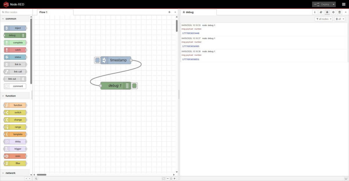
Hello world.
The hello world for Node-RED is dragging an inject node, a debug node, wiring them together and clicking Deploy. Pressing the inject node’s button sends a timestamp into the debug panel — three button presses produce three timestamps in the right-hand pane. Two nodes, one wire, no code.
Pros.
- Zero glue code for common cases. Wiring a button to a serial port is two nodes and a wire.
- The dashboard palette generates a polished UI from the same flow that processes the data — no separate frontend project.
- Huge ecosystem of community nodes for almost any protocol or service (MQTT, modbus, Slack, Telegram, etc.).
- Local-first by default. Runs entirely on the laptop, no cloud account, no telemetry.
- Flows export as JSON, version-controllable.
Cons.
- Visual diffs of
flows.jsonare unreadable. Two people editing the same flow in parallel cannot merge cleanly. - Once a flow gets non-trivial (20+ nodes, branching logic, state) it becomes harder to follow than equivalent code.
- The dashboard layout system is rigid — pixel-perfect UI is not realistic.
- Debugging is painful: there is no breakpoint, only the
debugnode.
Files.
group-node-red-hello-world.json— the two-node hello world flow (inject → debug). Importable via ☰ → Import in any Node-RED instance.
mit app inventor.
One-line description: web-based block programming environment for building Android apps, developed at MIT as the educational successor to Google’s App Inventor.
Setup and installation.
Zero local install. The IDE runs entirely at appinventor.mit.edu and only requires a Google account to sign in. To test apps on a phone, install the MIT AI2 Companion from the Play Store and scan the QR code shown by the IDE.
To package an app as a standalone APK there is a Build → Android App (.apk) option in the IDE — no Android SDK required locally.
Hello world.
The hello world for App Inventor is a button + a label: tap the button on the phone, the label below it changes its text. The model is two-pane: Designer lets me drag UI components onto a phone-shaped canvas, Blocks lets me wire their events with snap-together blocks of code-shaped logic.
After signing in with a Google account the platform showed a welcome dialog — set-up announcement, no actions required:
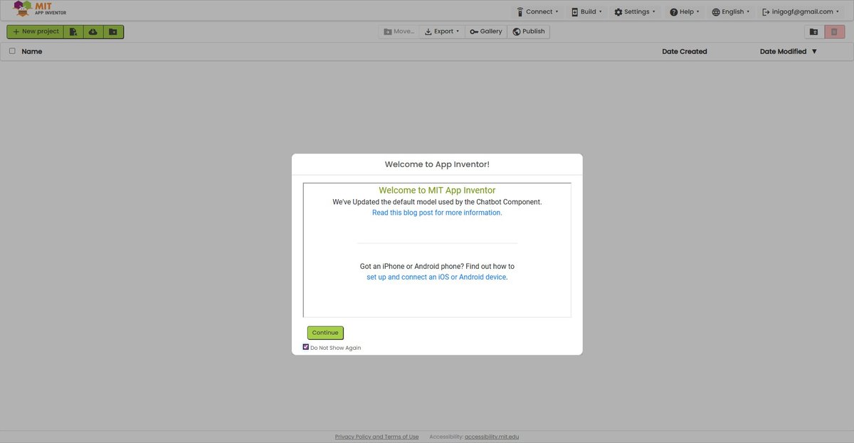
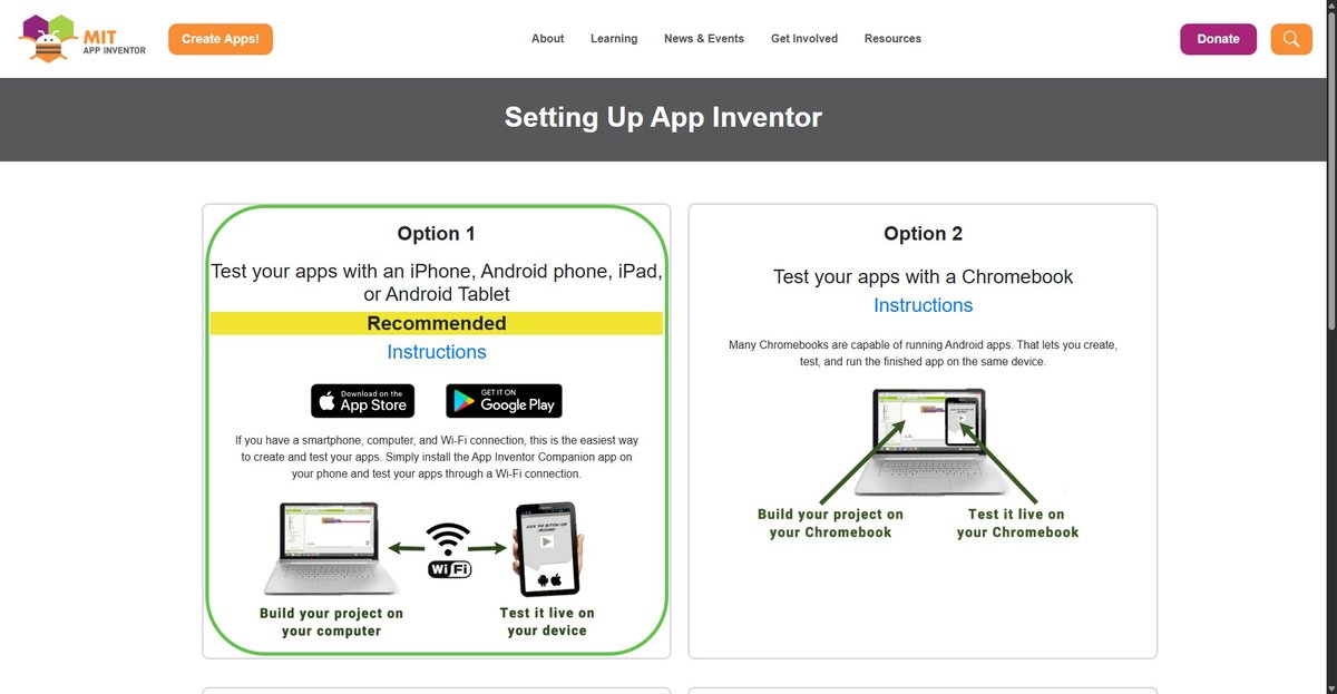
The setup page links from the dialog explain the recommended way to test an app: install the MIT AI2 Companion app on an Android or iOS device, connect to the same Wi-Fi as the laptop, scan a QR code shown by the IDE.
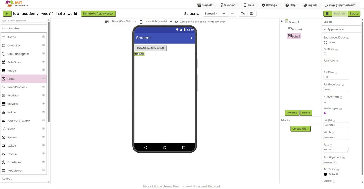
After creating a new project named fab_academy_week14_hello_world (App Inventor only allows letters, numbers and underscores), I dropped a Button and a Label onto the Designer canvas. The button text is “Hello fab academy World!!”, the label starts with a placeholder text “fab label”:
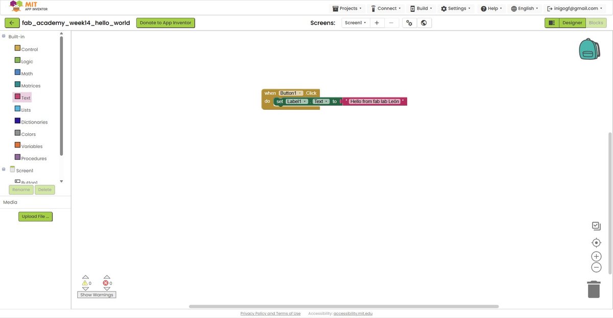
In Blocks mode I built the logic by dragging three pieces from the categories on the left palette:
when Button1.Click do(yellow, from the Button1 drawer in Components) — the event handler that fires when the button is tapped.set Label1.Text to(green-orange, from the Label1 drawer) — the setter that writes a new value into the label."Hello from fab lab León"(red, from the Text category in Built-in) — a literal string to put into the setter.
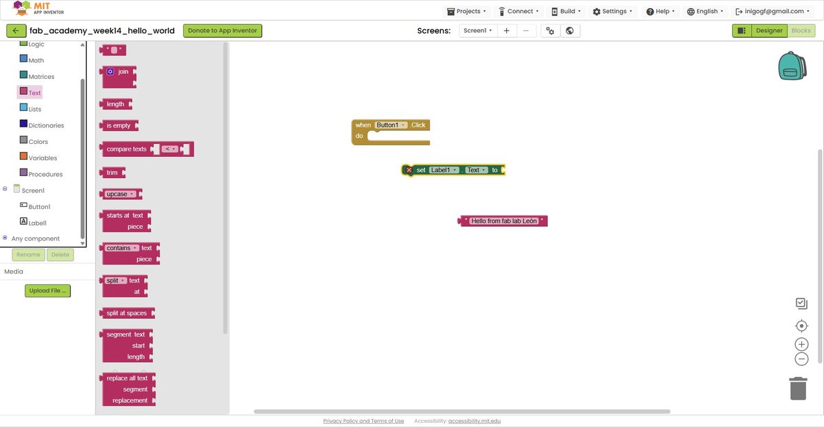
The blocks are shape-coded — you cannot connect them in a way that does not type-check. The string block has a “plug” shape that fits the “socket” of set Label1.Text to; that combined block has a flat top that fits inside the do slot of the event handler. Snapping all three together produces the rule: when Button1 is clicked, set Label1’s Text to the string "Hello from fab lab León". Three blocks, no syntax to memorise, no commas missing, no semicolons forgotten.
Connected the IDE to the phone via QR code and ran the app:
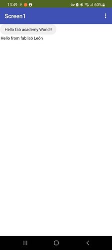
End-to-end cycle confirmed: web IDE on the laptop → live preview on a real phone over Wi-Fi → user input on the phone triggers logic defined in Blocks → label updates accordingly. Total time including signup and Companion app install: ~25 minutes.
Pros.
- Truly zero install on the laptop side. Anyone with a browser and a Google account can start building.
- Live testing on a real phone via the companion app — no emulator, no signing certificate dance.
- The block model is genuinely beginner-friendly. You can teach a non-programmer to build a working app in under an hour.
- BLE, Wi-Fi, sensor access, camera, file storage — all available as drag-in components.
Cons.
- Vendor lock-in: the source format
.aiais only readable by App Inventor itself. - Block programs are hard to review at scale — there is no diff, no merge, no unit test.
- iOS support is limited to the companion app; you cannot package standalone iOS apps the same way as APKs.
- Requires a Google account, which conflicts with privacy-first workflows.
- The aesthetic ceiling is low — apps look like App Inventor apps even when polished.
Files.
- Project source:
fab_academy_week14_hello_world.aia— exported via Projects → Export selected project (.aia) to my computer in the App Inventor IDE. Can only be opened by re-importing into App Inventor itself.
processing (p5.js via openprocessing).
One-line description: p5.js is the JavaScript reimplementation of Processing — a creative-coding library focused on graphics, sound and interaction. OpenProcessing hosts the editor and a public gallery of sketches.
A clarification matters: p5.js is not Processing. They share the API style and the philosophy (setup() / draw(), simple drawing primitives, immediate-mode UI) but p5.js runs in the browser on JavaScript, while Processing-Java is a desktop IDE. David Fernández’s 2025 documentation used Processing-Java with processing.serial to read the XIAO over USB. That library does not exist in p5.js — the browser cannot open arbitrary COM ports. The modern equivalent is the Web Serial API, which lets a web page request user permission to open a serial port. Same security philosophy as WebSockets: the browser mediates.
Setup and installation.
Zero install. Open openprocessing.org, click Create a Sketch, write code, hit play. An OpenProcessing account is optional but useful for saving sketches.
If at some point I want to run sketches locally, the alternative is the p5.js web editor (also browser-based) or downloading p5.js into a local HTML file.
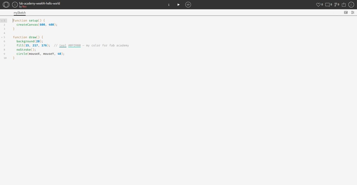
Hello world.
The canonical p5.js hello world is a circle that follows the mouse — three lines in setup(), three in draw(). The model is dead simple: setup() runs once on load, draw() runs 60 times per second, you paint pixels into a <canvas>.
function setup() {
  createCanvas(600, 400);
}

function draw() {
  background(20);
  fill(15, 217, 176);  // teal #0FD9B0 — my fab academy accent colour
  noStroke();
  circle(mouseX, mouseY, 40);
}
OpenProcessing opens with a default template (a 100×100 grey canvas with a circle that traces the mouse path). I deleted it and pasted the snippet above. Two seconds later the circle was tracking the cursor with a clean dark background.
A 10-second screen recording of the sketch in action:
Live sketch: openprocessing.org/sketch/2931981 — anyone with the URL can run it in their browser without any installation.
Pros.
- Truly zero install — works on any device with a browser, including a phone.
- Code-based: everything is plain JavaScript, version-controllable, diff-able, AI-assistable.
- Massive community gallery on OpenProcessing for inspiration and learning.
- Direct path to publishing: a sketch is already a web page, anyone with the URL can run it.
- Web Serial API opens a clean route to talk to embedded devices without a backend.
Cons.
- Browser-only. No native desktop or mobile app without wrapping (e.g. Electron or Capacitor).
- Performance is bound by the browser — heavy graphics or large datasets hit limits faster than a native app.
- Web Serial is Chromium-only. Safari and Firefox do not implement it.
- p5.js focuses on creative coding, not on building business UIs — there are no native widgets (buttons, sliders, dropdowns) without using DOM elements alongside the canvas.
Files.
- Live sketch on OpenProcessing: openprocessing.org/sketch/2931981.
- The source code is the seven-line snippet shown above — short enough that there is no separate file to attach.
summary table.
After running the hello world for each tool, the comparison fills in cleanly:
| Dimension | Node-RED | App Inventor | p5.js |
|---|---|---|---|
| Runtime location | Desktop server + browser UI | Android phone | Browser |
| Authoring model | Visual dataflow nodes | Visual blocks + UI Designer | JavaScript code |
| Transport to MCU | USB serial, MQTT, WebSocket, HTTP | BLE, Wi-Fi (HTTP), WebSocket via extensions | Web Serial, WebSocket, fetch (HTTP) |
| Setup cost | Node.js + npm install -g node-red + 2 palettes | None on laptop (web IDE) + Companion app on phone | None (web IDE only) |
| Iteration speed | Save → Deploy (~1 s) | Live (Companion app reflects changes immediately) | Save → reload (~1 s) |
| License & stewardship | OSS (Apache 2.0), OpenJS Foundation | OSS (Apache 2.0), MIT | OSS (LGPL 2.1), Processing Foundation |
| Maintainability | High (JSON export, mainstream stack) | Low (.aia proprietary format, no diff/merge) | High (plain JS, version-controllable) |
| Aesthetic ceiling | Demo → Production | Demo | Production (creative coding gallery) |
The two dimensions that did the most work in differentiating the tools were maintainability and runtime location, not the surface ones. p5.js and Node-RED both produce plain text artefacts (JS source / JSON flow) that any future maintainer can read. App Inventor’s .aia is a proprietary bundle that nobody outside App Inventor can usefully open. That alone disqualifies it from anything I would still want to maintain in two years.
recommendations.
Where each tool fits best, based on the comparison above:
- Node-RED — wire heterogeneous things together (sensors, APIs, messaging, dashboards) on a server you control. Best when “the UI is a side effect of the data flow” rather than the main product.
- MIT App Inventor — teach app development to non-programmers, prototype Android apps in an afternoon, classroom or workshop contexts. Not a foundation to build long-term software on.
- p5.js / OpenProcessing — interactive visualisations, creative coding, anything where the UI itself is the artefact. Pairs well with Web Serial for browser-driven hardware demos.
For the standing desk’s eventual user interface — whether a touchscreen or a button-based panel — none of these three tools are the right answer; that work belongs on the master microcontroller and is deferred to System Integration. But for prototyping interfaces while developing the project, Node-RED is the natural choice and that is why it powers the individual assignment below.
individual assignment.
The individual assignment is a bidirectional bridge between my own board and Node-RED running on the laptop:
- Board → host: the button on the board sends an event up to Node-RED.
- Host → board: a switch on the dashboard sends a command down to the board to turn the LED on or off.
Hardware: XIAO RP2040 Fab board from Week 06 (LED on D9, button on D10 with an external 10k pull-down resistor; switch closes to 3V3, so pressed = HIGH).
Application tool: Node-RED running locally on Windows (already documented in setup and installation below).
Transport: USB serial. Simplest possible link — no Wi-Fi credentials, no network configuration, the board plugged into the laptop’s USB-C port and that’s it.
┌────────────────────┐     serial @ 9600 baud      ┌────────────────────────┐
│  XIAO RP2040       │ ◄──────────────────────────►│  Node-RED on laptop    │
│  • button (D10)    │   newline-terminated text   │  • serial-in / -out    │
│  • LED    (D9)     │                             │  • dashboard widgets   │
└────────────────────┘                             └────────────────────────┘
setup and installation.
Recorded here for reproducibility — if I (or anyone else) wipes the laptop tomorrow, this is the minimum to get back to a working Node-RED.
1. Node.js LTS (≥ 20). Node-RED runs on Node.js. Install from nodejs.org or via winget:
winget install OpenJS.NodeJS.LTSVerify in a new PowerShell session (PATH is updated only after restart):
node --version
npm --version
2. Node-RED. Install globally with --unsafe-perm (recommended by Node-RED’s Windows guide — needed for native modules like serialport):
npm install -g --unsafe-perm node-red3. Launch.
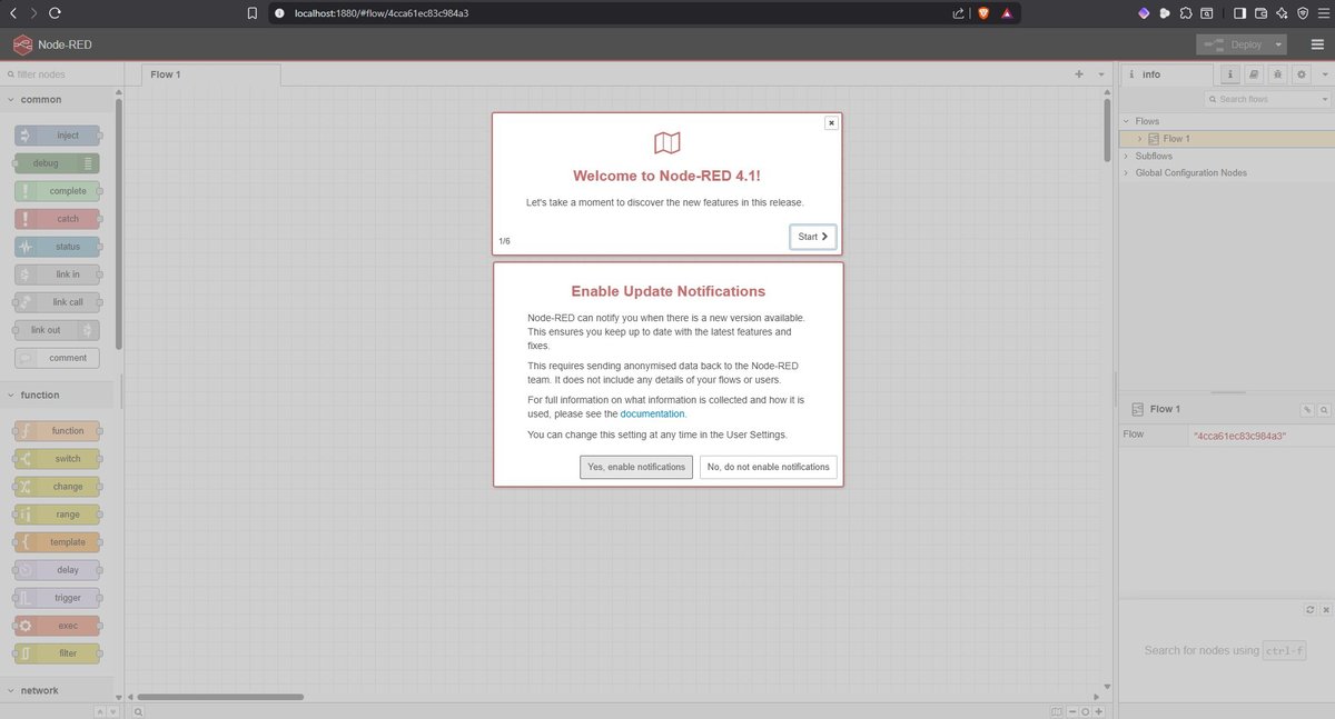
node-redOpen http://localhost:1880 in the browser for the editor, http://localhost:1880/dashboard for the dashboard.
4. Required palettes (install from the Node-RED editor: ☰ → Manage palette → Install):
| Palette | Version | Purpose |
|---|---|---|
@flowfuse/node-red-dashboard | 1.30.2 | UI widgets (buttons, gauges, text). Dashboard 2.0. |
node-red-node-serialport | 2.0.3 | USB serial in/out nodes |
Note on Dashboard 2.0 vs the classic Dashboard. When searching for node-red-dashboard the catalogue first surfaces a result tagged deprecated. That is the classic Dashboard (1.x), no longer maintained. Its successor is @flowfuse/node-red-dashboard (Dashboard 2.0), now the official path. They are not API-compatible: nodes in Dashboard 2.0 are named ui-button, ui-switch, ui-text (with hyphen), and the live URL is http://localhost:1880/dashboard rather than /ui. Most tutorials online still reference the classic version — when an example uses a node called button (without ui- prefix), it is the deprecated one and the syntax does not transfer.
Versions of Node.js and Node-RED itself for this week’s setup:
node     v24.15.0
npm      11.12.1
node-red 4.1.8
Note: Node.js 24 is the Current branch, not LTS — when I installed it via winget install OpenJS.NodeJS.LTS, winget routed me to the latest stable (Node 24.15) rather than the LTS line (Node 22). Node-RED’s official guide accepts Node 18, 20, 22 or higher, so this is fine, but if a future package breaks unexpectedly this is the first thing to suspect. Node 24 itself enters LTS in October 2026.
why these choices.
Why Node-RED.
- It is exactly what Neil demonstrated, so the documentation value is clear.
- Visual dataflow is a different way of thinking from writing code — the assignment asks me to try something, not to default to my comfort zone.
- The dashboard palette generates the UI from the same flow that processes the data — no separate frontend project to maintain.
- Local-first by default. No cloud account, no telemetry, no Wi-Fi needed.
Why XIAO RP2040, not the ESP32-S3 also on the same socket.
- The board is already milled, soldered, tested. Reusing it removes one source of unknowns.
- USB serial is the simplest transport — no Wi-Fi credentials, no captive portals, no SSID scanning.
- It scopes the spiral to a single new variable (Node-RED) rather than introducing two at once (Node-RED + Wi-Fi).
- A future spiral can swap the XIAO for the ESP32-S3 (same socket on the PCB) and switch from USB serial to WebSockets, exactly mirroring Neil’s demo.
how the application communicates with the microcontroller.
This is the contract between the two pieces of software. Documenting it explicitly here matters because it is the part that makes the whole thing work, and the part that is easiest to get wrong silently.
Physical link. Standard USB-C cable from the XIAO RP2040 to the laptop. The RP2040 firmware exposes a virtual serial device, which Windows enumerates as a COM port (COM3 on this machine — the number depends on what the OS has assigned previously). No USB-to-UART chip in between, no level shifters. The cable is the entire transport layer.
Serial parameters. Plain 8N1 at 9600 baud, no flow control, both ends configured identically:
| Parameter | Value | Notes |
|---|---|---|
| Baud rate | 9600 | Plenty for a few events per second; slow enough that any monitor handles it without tweaking |
| Data bits | 8 | Default |
| Parity | None | Default |
| Stop bits | 1 | Default |
| Flow control | None | None of the messages are large enough to need it |
The Serial.begin(9600) line in the firmware and the Baud Rate: 9600 dropdown in the Node-RED serial-port config are the two ends that need to match. If they don’t, the line carries garbage but neither side reports an error — the symptom is “I see instead ofPRESSED` in the dashboard”. This is exactly the silent failure I was warning about above.
Application protocol. Plain ASCII, one message per line, terminated by \n. No JSON, no binary framing, no checksum. The protocol is small enough (four messages) that the readable form pays for itself when debugging with a serial monitor.
The full vocabulary:
| Direction | Message | Trigger | Effect |
|---|---|---|---|
| Board → Host | PRESSED\n | Button transitions LOW → HIGH (debounced 50 ms) | Dashboard text shows PRESSED |
| Board → Host | RELEASED\n | Button transitions HIGH → LOW (debounced 50 ms) | Dashboard text clears |
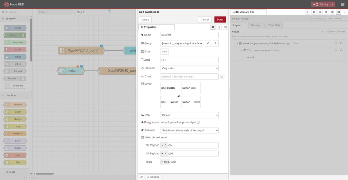
| Host → Board | ON\n | User flips ui-switch to ON | LED turns on (digitalWrite(D9, HIGH)) |
| Host → Board | OFF\n | User flips ui-switch to OFF | LED turns off (digitalWrite(D9, LOW)) |
Why \n matters in both directions. The serial-in node in Node-RED is configured to split incoming bytes on \n — that is what tells it where one message ends and the next begins. The serial-out node has the symmetric setting Add character to output messages: \n so that every payload sent from the host arrives at the firmware with a trailing newline. The firmware’s parser reads bytes one at a time and treats \n (and \r, defensively) as the end-of-message marker. Without that newline at either end, the messages would concatenate on the wire and neither parser would know when to act.
Sequence diagram of a typical exchange. Times are in milliseconds from the first physical interaction. The ~ on the right-side timestamps reflects that user-driven events have human latency; the 50 ms after the press / release is the firmware’s own debounce window.

What is on each side of the contract.
| Concern | Lives on the firmware | Lives in Node-RED |
|---|---|---|
| Reading the button | Polling digitalRead(D10) in loop() | — |
| Debouncing | 50 ms via timestamp comparison | — |
| Encoding events | Serial.println("PRESSED") etc. | — |
| Parsing serial bytes | Char-by-char with \n terminator | serial-in node, split on \n |
| Translating events to UI | — | function 1 rewrites RELEASED → "" |
| Rendering the UI | — | ui-text, ui-switch widgets |
| Encoding commands | — | ui-switch payload + serial-out adds \n |
| Driving the LED | digitalWrite(D9, …) based on parsed command | — |
This is the kind of split worth thinking through up front: every concern has one owner, and the wire between them carries only the four messages above. If something goes wrong, the first question is “which side has the bug?”, and the answer is always one or the other, never “the protocol is ambiguous”.
spiral 1 — edge-triggered “PRESS”.
The first protocol I designed was the simplest possible thing that could work: the firmware sends a single PRESS\n on every button press, the dashboard shows the latest event in a text widget. Like an onClick event in a UI.
The flow: four nodes, one wire each direction.
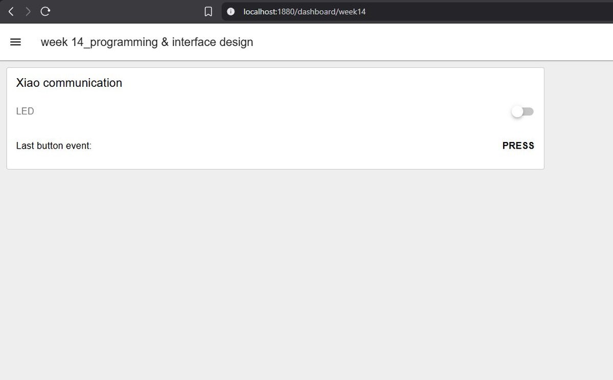
This worked, but the dashboard ended up showing PRESS and staying on PRESS forever — every press just rewrote the same word. As a demo for the lab review it didn’t feel illustrative enough: a viewer cannot distinguish a fresh event from a stale one. So I evolved the protocol.
spiral 2 — level-reporting “PRESSED” / “RELEASED”.
Spiral 2 sends two distinct events: PRESSED\n on the falling edge of the button (after debounce), RELEASED\n on the rising edge. The dashboard now reflects the current state of the button in real time — pressing shows PRESSED, releasing clears the text. It is a small change with much better feedback.
The trade-off: the firmware is now slightly more complex, and Node-RED needs an extra function node between the serial-in and the ui-text to translate RELEASED into an empty string (otherwise the text would just flip between the two words instead of clearing).
firmware.
The firmware (Arduino, C++) reads the button with a 50 ms debounce and writes events to the serial port. It also listens for ON/OFF commands from the host and drives the LED accordingly.
🤖 Claude (Anthropic) — sketch generation prompt:
Write me an Arduino sketch for a XIAO RP2040 with a button on D10 (external 10k pull-down to GND, switch closes to 3V3, so pressed = HIGH) and an LED on D9. Send PRESSED\n to serial on the falling edge and RELEASED\n on the rising edge, both debounced at 50 ms. Also listen on the same serial port for the strings ON and OFF (newline-terminated) and drive the LED accordingly. 9600 baud. No third-party libraries.
Resulting sketch:
tab: xiao-rp2040-node-red-bridge.ino | xiao-rp2040-node-red-bridge.ino
// Fab Academy 2026 — Week 14 — Individual assignment
// XIAO RP2040 ↔ Node-RED over USB serial
//
// Hardware (Week 06 PCB):
//   D9  → LED (output, active HIGH)
//   D10 → push button via external 10k pull-down to GND, switch closes to 3V3
//         → pressed = HIGH, released = LOW
//
// Protocol (newline-terminated plain text):
//   Board → host: "PRESSED\n"  on rising edge  (button pushed down, debounced)
//                 "RELEASED\n" on falling edge (button let go,    debounced)
//   Host → board: "ON\n"  → LED on
//                 "OFF\n" → LED off

const int LED_PIN     = D9;
const int BUTTON_PIN  = D10;

const unsigned long DEBOUNCE_MS = 50;
int           lastStableState   = LOW;    // external pull-down: LOW = released
int           lastReadState     = LOW;
unsigned long lastChangeMs      = 0;

String  inputBuffer = "";

void setup() {
  pinMode(LED_PIN,    OUTPUT);
  pinMode(BUTTON_PIN, INPUT);   // external pull-down on the PCB, no internal pull needed
  digitalWrite(LED_PIN, LOW);
  Serial.begin(9600);
}

void loop() {
  handleButton();
  handleSerial();
}

void handleButton() {
  int reading = digitalRead(BUTTON_PIN);

  if (reading != lastReadState) {
    lastChangeMs  = millis();
    lastReadState = reading;
  }

  if ((millis() - lastChangeMs) > DEBOUNCE_MS) {
    if (reading != lastStableState) {
      lastStableState = reading;
      if (lastStableState == HIGH) {
        Serial.println("PRESSED");
      } else {
        Serial.println("RELEASED");
      }
    }
  }
}

void handleSerial() {
  while (Serial.available() > 0) {
    char c = Serial.read();
    if (c == '\n' || c == '\r') {
      if (inputBuffer.length() > 0) {
        if      (inputBuffer == "ON")  digitalWrite(LED_PIN, HIGH);
        else if (inputBuffer == "OFF") digitalWrite(LED_PIN, LOW);
        inputBuffer = "";
      }
    } else {
      inputBuffer += c;
    }
  }
}
tab: end
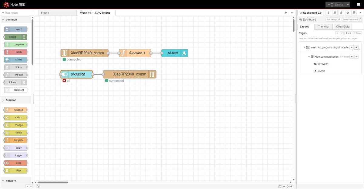
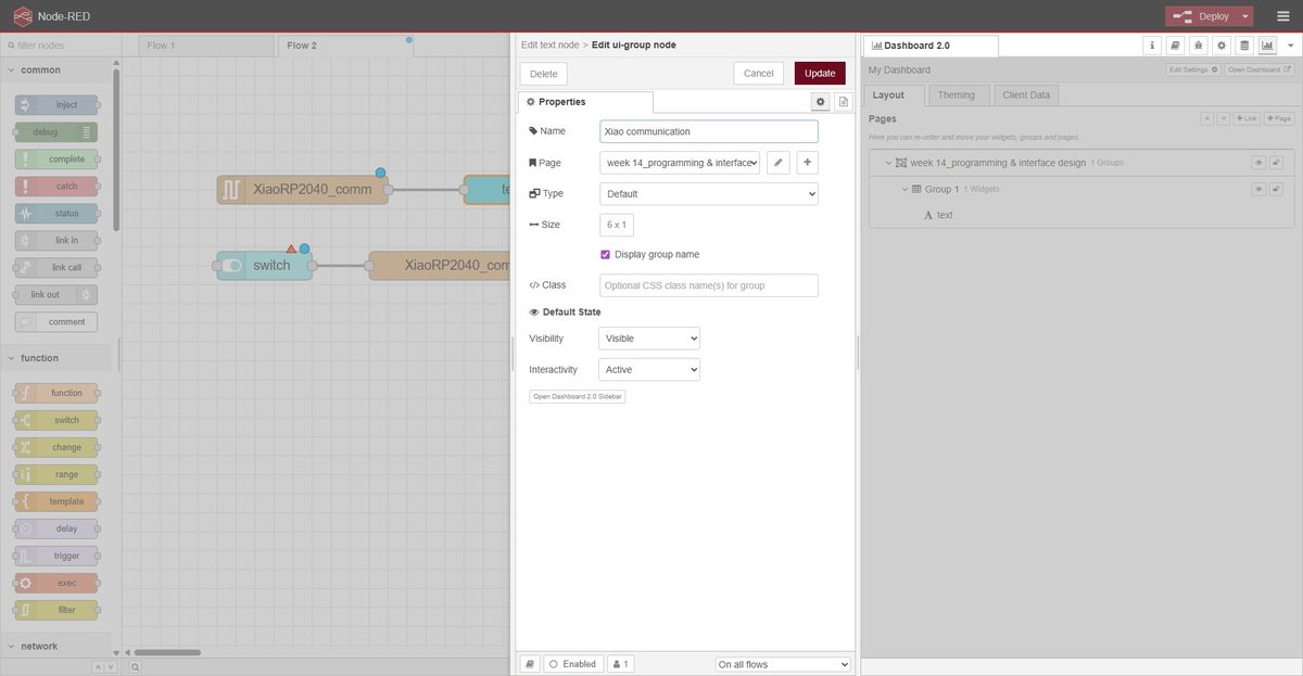
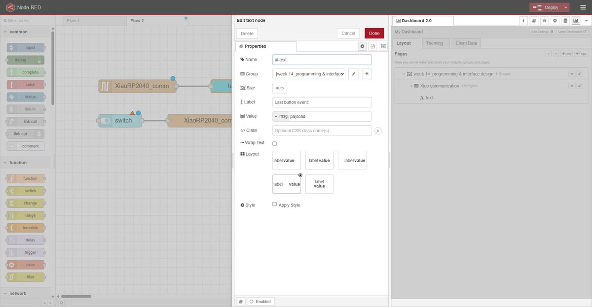
node-red flow — node configuration.
Three nodes need configuring before deploy. Each one shown below in its own dialog.
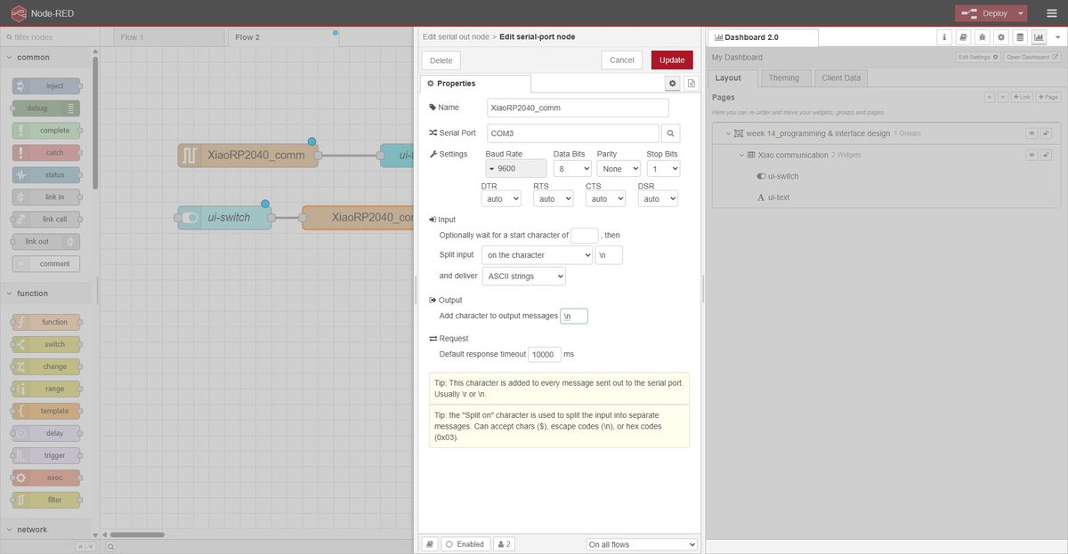
The dashboard hierarchy on the right side of the editor shows the layout: a single page (/dashboard/week14) containing one group (“Xiao communication”) with the two widgets stacked vertically.
node-red flow — translation function.
The function node between serial in and ui-text rewrites the incoming message so the text widget shows the current button state. PRESSED is forwarded as-is, RELEASED is rewritten to an empty string (which clears the widget), and any unknown payload is dropped.
🤖 Claude (Anthropic) — function node prompt:
I have a Node-RED function node that receives msg.payload from a serial-in node. The serial frames are PRESSED\n and RELEASED\n. Write a JS function that, on PRESSED, forwards msg.payload = "PRESSED"; on RELEASED, forwards msg.payload = ""; on anything else, drops the message. Use .trim() to be defensive against trailing newlines.
Resulting JS:
tab: node-red-translate-function.js | node-red-translate-function.js
// serial in delivers payload as string with \n already stripped, but trim() defensively
const event = msg.payload.trim();

if (event === "PRESSED") {
    msg.payload = "PRESSED";
} else if (event === "RELEASED") {
    msg.payload = "";
} else {
    // Unknown event — drop the message
    return null;
}

return msg;
tab: end
result — running demo.
The full bidirectional bridge in action: pressing the physical button on the board updates the dashboard text in real time; flipping the dashboard switch turns the LED on the board on and off.
design decisions.
- Frame format: plain text (
PRESSED\n,RELEASED\n,ON\n,OFF\n). JSON is overkill for four discrete messages and the line is human-readable in a serial monitor while debugging. - Baud rate: 9600. More than enough for a few events per second and slow enough that any monitor handles it without configuration tricks.
- Edge-triggered vs level-reporting: evolved across the two spirals. Final choice is level-reporting (PRESSED + RELEASED) because the dashboard mirrors the button state in real time, which is more illustrative for a demo even if slightly more verbose on the wire.
- Pull-down on the button: part of the Week 06 PCB design — external 10k from the pin to GND, switch closes the pin to 3V3. Pressed = HIGH, released = LOW. This is the opposite of the more common “button-to-GND + INPUT_PULLUP” pattern, and is reflected in the firmware (
pinMode(BUTTON_PIN, INPUT), no internal pull). - Shared serial-port configuration in Node-RED: both
serial inandserial outreference the same port config object (XiaoRP2040_comm). Creating two separate configs would have Node-RED open COM3 twice and one of them would fail with “port busy”.
reflections.
On the group assignment. Comparing three interface tools side-by-side made the abstract conversation about “low-code vs code vs visual” very concrete. The cleanest takeaway was that the format the tool stores its source in matters more than the authoring style. App Inventor felt nicer than Node-RED to use during the hello world, but its .aia bundle would be a dead artefact in two years; Node-RED’s flows.json would still be readable. That is the kind of property I would not have thought to look for without forcing myself to fill in a maintainability column.
On the individual assignment. The first spiral worked but the demo was hard to read — “the dashboard says PRESS, but it has been saying PRESS for the last ten seconds, so what am I supposed to be looking at?”. Splitting the protocol into PRESSED + RELEASED costs almost nothing on the firmware side and pays off immediately in the demo: the dashboard reflects the physical state of the button as I am pressing it. That is the kind of decision that a tutorial would never raise — you only see the need for it when you watch someone else watching your demo.
A more practical lesson was about resource ownership of a single COM port. Arduino IDE, the Arduino IDE serial monitor, and Node-RED’s serial-in node all want exclusive access to COM3. The workflow that ended up working is: stop the Node-RED process in the terminal before flashing the board, then restart it. Disabling the serial nodes from the editor was not enough on its own once Node-RED had cached a handle to the port. This is the kind of thing that will bite again the next time I bridge an embedded device to a desktop tool, so it is worth writing down.
design files.
node-red flow.
week14-flows.json — full Node-RED export of the individual assignment flow (Week 14 — XIAO bridge tab, the shared serial-port config XiaoRP2040_comm, the ui-page at /dashboard/week14, the function node, and the global node-red-node-serialport + @flowfuse/node-red-dashboard versions used). Importable into any Node-RED 4.x instance via ☰ → Import → select file.
group-node-red-hello-world.json — the trivial inject + debug flow from the group assignment hello world.
xiao rp2040 firmware.
xiao-rp2040-node-red-bridge.ino — Arduino sketch shown in full above. Compiles with the arduino-pico core, board target Seeed XIAO RP2040.
node-red translation function.
node-red-translate-function.js — body of the function node between serial in and ui-text (also embedded inline in the flow JSON above). Standalone copy provided so it is easy to paste into a different Node-RED setup.