Molding & Casting
weekly schedule.
| Time block | Wed | Thu | Fri | Sat | Sun | Mon | Tue | Wed |
|---|---|---|---|---|---|---|---|---|
| Global class | 3 h | |||||||
| Local class | 1 h | 1.5 h | ||||||
| Research | 1 h | 1 h | ||||||
| Design | 3 h | 2 h | ||||||
| Fabrication | 1 h | 3 h | 2 h | |||||
| Documentation | 2 h | 3 h | ||||||
| Review |
overview.
This week covers molding & casting: producing parts by pouring a liquid material into a cavity and waiting for it to solidify. Two stages, three pieces:
- Positive (master) — the geometry I want to reproduce.
- Negative mould — fabricated around the positive (in this case milled into wax). The silicone is poured on top and cures into a flexible mould.
- Cast part — final piece, made by pouring plaster into the silicone mould.
I am not connecting this week directly to the standing desk final project. The original idea was a silicone foot for the DN50 leg tubes, but after talking with Nuria the available silicone (Reschimica RPRO 30) is a mould-making silicone, not a product silicone — using it to cast the final part would mean pouring silicone into a silicone mould, which only works with two distinct hardnesses and a release agent. Nuria recommended a safer route: wax milling + silicone mould + plaster casting, with a parallel attempt using a 3D-printed PLA master to compare both routes side by side.
To make the printing-vs-milling comparison required by the group assignment more substantive, I will also 3D-print the brick in PLA on my Bambu Lab A1 at home and post-process it (XTC-3D coating, sanding) until the layer lines are no longer visible. The post-processed PLA brick becomes a second positive master that I can use to compare cast results against the wax-milled master — same silicone, same plaster, only the master fabrication route changes.
The piece I designed is a LEGO-style brick of my own dimensions — 2×3 studs, scaled and not compatible with the LEGO system. It works well as an assignment piece: rectangular base with curved features (cylindrical studs and tubes), enough geometry to require a roughing + finishing pass, and a clear mating between two halves of the mould.
learning objectives.
- Understand the mould-making workflow: positive → negative mould → cast part.
- Read and interpret SDS for wax, silicone and resin, and identify the relevant PPE.
- Compare CNC milling vs 3D printing as routes to fabricate the negative mould.
- Design a part that fits both the process constraints (parting plane, draft, registration, sprue, vent) and the available stock and tooling.
- Practice safe handling of two-component reactive materials.
assignments.
Group assignment
- Review the SDS for each molding/casting material available at Fab Lab León
- Make and compare test casts with each material
- Compare 3D printing vs CNC milling for moulds
Individual assignment
- Design a mould around the chosen process
- Produce it with a smooth surface finish that does not show production marks
- Cast parts in it
- (Extra credit) Use more than two mould parts
group assignment.
The group assignment for Fab Lab León — reviewing the SDS of each available molding/casting material, making and comparing test casts, and comparing 3D printing against CNC milling — is documented on this page and on the Fab Lab León 2026 Group Page. The three requirements map to the sections below: the SDS review is in materials available at Fab Lab León; the printing-vs-milling comparison runs from the route table in printing vs milling — comparing the two routes for the master through to the side-by-side cast results in milling vs printing; and the test casts are covered in the silicone test mix and plaster test mix sections of the individual assignment.
materials available at Fab Lab León.
Three materials so far. SDS reviewed below for the two I will use this week.
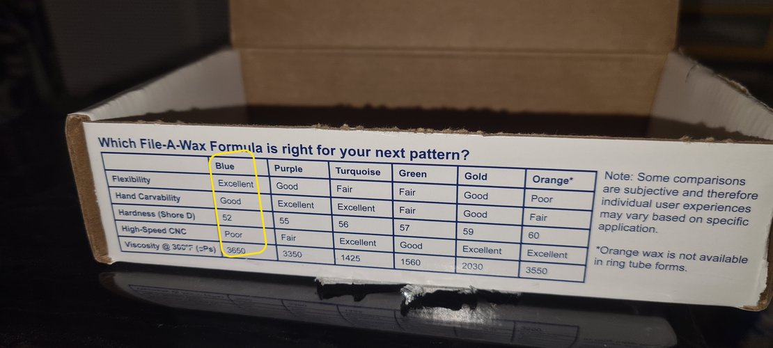
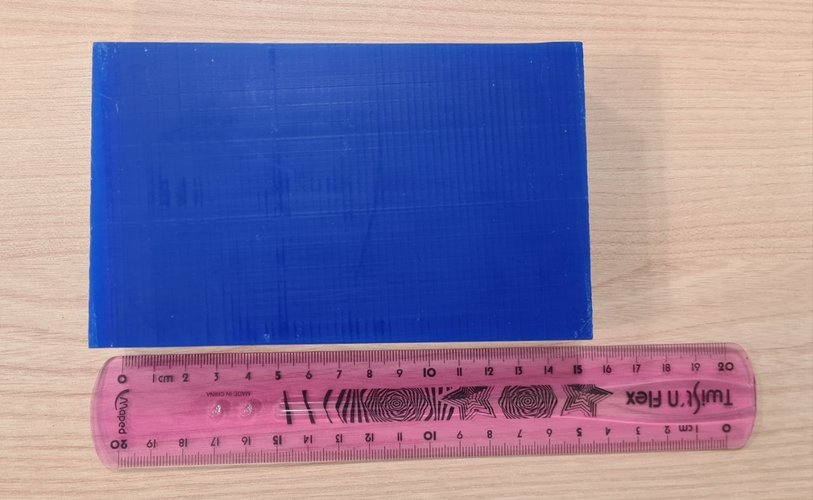
tab: Wax — Ferris File-A-Wax Blue
- Use: carving wax, milling wax (for negative moulds).
- Manufacturer: Freeman Manufacturing & Supply Company.
- Stock size at Fab Lab León: 146 × 90 × 34 mm (nominal 5-3/4” × 3-1/2” × 1-1/2”).
- Hazards: not classified as hazardous under OSHA 29 CFR 1910.1200. Molten product can cause thermal burns; otherwise no GHS label required.
- PPE for milling: safety glasses with side shields. Gloves only needed if handling molten wax.
- Storage: sealed container, away from heat and direct sunlight.
- Disposal: follow local regulations; not regulated for transport.
- Datasheet: Ferris File-A-Wax Blue SDS.
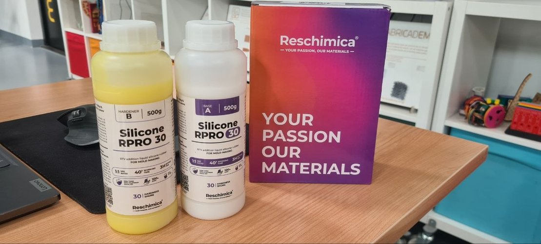
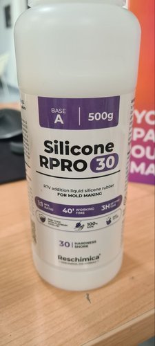
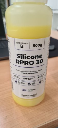
tab: Silicone — Reschimica RPRO 30
- Type: RTV addition liquid silicone rubber for mould making, platinum-catalysed (non-toxic).
- Mix ratio: 1:1 by weight (Base A + Hardener B, both 500 g bottles in the lab).
- Working time: 40 min.
- Setting time: 3 h.
- Hardness: Shore 30.
- Hazards: the SDS classifies the product as non-hazardous under EU CLP Regulation 1272/2008. Contains crystalline silica but, being in liquid form, no respirable fraction is released, so the STOT RE classification does not apply.
- PPE: nitrile gloves, safety glasses. Work in a ventilated area. Do not eat or drink while handling.
- Inhibition warning: like all platinum-catalysed silicones, it can fail to cure in contact with sulphur, latex, tin compounds, and uncured photopolymer resins. This is why SLA resin masters are not used with this silicone — Nuria warned in our local class on Apr 24 that “silicones do not cure well on the resin-printed mould”, the same effect Adrián mentioned in the Apr 22 global class citing Pablo Núñez’s bootcamp tests. PLA does not have this problem, so it works as a master material for FDM 3D printing.
- Manufacturer: Reschimica srl (Tavarnelle Val di Pesa, Italy).
- Datasheet: Reschimica RPRO 30 SDS (Italian).
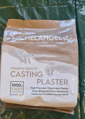
tab: Casting material — Algaplay Michelangelo
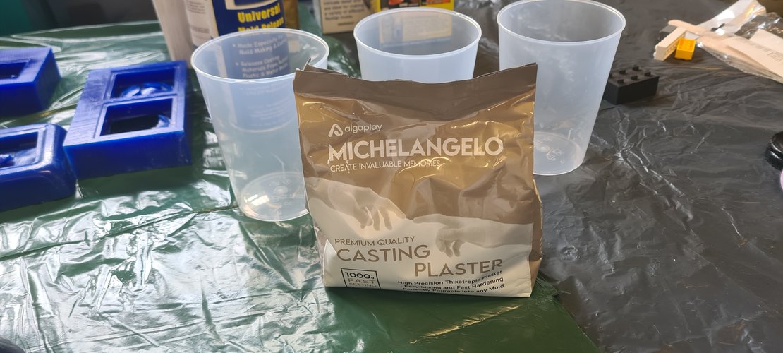
The casting material at the lab turned out not to be a polyurethane resin but a synthetic resin powder designed to be mixed with water like a plaster. Specifically: Algaplay Michelangelo Casting Plaster, described by the manufacturer as a 99.9% pure synthetic resin powder.
Mixing and timing:
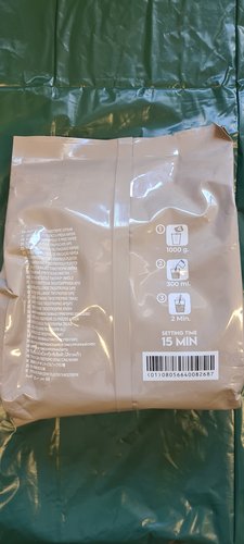
- Mix ratio: 1 kg powder : 0.30 l water (≈ 3.3 : 1 by weight).
- Working time: 10–12 min at 20 °C.
- Setting time: 15–20 min.
- Mould removal: 20–40 min after pouring.
- Full hardening: ~8 h in a dryer at max 40 °C, otherwise longer at room temperature.
Properties relevant to this week:
- Low thermal peak (~30 °C) during curing, so the silicone mould is not stressed.
- Very low expansion — the casted part faithfully reproduces the mould.
- Non-toxic, water-cleanable tools, biodegradable end product.
- Final hardness “similar to porcelain” (manufacturer claim — surface hardness > 300 N/mm²).
- Can be coloured in mass or on the surface (acrylic, water-based, solvent).
Procedure recommended by the manufacturer: fill the container with water first, then sprinkle the powder until absorbed, then stir 2 min by hand or with a low-rpm mixer (≤ 300 rpm) avoiding air bubbles.
Safety note: the product is classified as non-hazardous, no special PPE required beyond the basic dust mask while handling the dry powder.
tab: Surface coating — Smooth-On XTC-3D
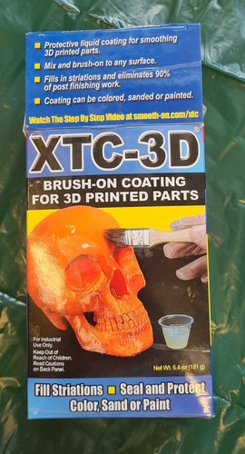
A brush-on epoxy coating by Smooth-On, designed to smooth FDM 3D-printed parts by filling in the layer striations. The manufacturer claims the product eliminates 90% of post-finishing work compared with sanding alone.
- Type: two-component epoxy coating (Part A resin + Part B hardener), brush-on. Mix ratio 2A : 1B by volume (100A : 42B by weight); cures clear and hard (Shore 80D after 7 days); contains no VOCs, phthalates or phosphates.
- Use in this assignment: smoothing the FDM PLA master before the silicone pour, so that the layer lines do not get reproduced into the silicone mould and from there into the plaster cast.
- Working time / cure: pot life ~10 min in a concentrated mass (≈15 min poured into a flat tray, which reduces the exotherm), ~20 min thin-film working time once brushed out. Tack-free in ~2 h, cured as a thin layer in ~3.5 h.
- Hazards: unlike the wax, silicone and plaster, this is the one material this week that is classified hazardous. The epoxy resin and the amine hardener are skin and eye irritants and potential skin sensitisers — repeated or prolonged skin contact can trigger an allergic reaction. Mixing is exothermic (generates heat).
- PPE: nitrile gloves (not optional here), safety glasses, long sleeves, work in a ventilated area; a NIOSH-grade respirator is recommended. Do not mix in glass or foam containers — only plastic, metal or wax-free paper.
- Manufacturer: Smooth-On XTC-3D product page.
- Datasheet: Smooth-On XTC-3D SDS.
This is the same manufacturer as the Universal Mold Release used on the wax master (Track A), so the chemistry is consistent across both routes.
tab: Release agent — Reschimica R-Wax Release
A wax-based release agent by Reschimica (product code APDIST01), sprayed over the cured XTC-3D coating before the silicone pour. Being wax-based it does not inhibit platinum-cure silicone, and it is the same supplier’s match for the RPRO 30 — which removes the inhibition risk a random aerosol release could otherwise introduce.
- Type: wax-based release agent, spray application.
- Use in this assignment: double duty — it stops the silicone bonding to the cured XTC-3D (Smooth-On’s own note is that liquid rubbers adhere to cured XTC-3D), and it protects the master so the cured silicone peels off cleanly. Reschimica recommends it specifically for original models from which a silicone mould is taken.
- Application: for the first use on a fresh master, three passes spaced ~10 min apart; a single pass before each subsequent cast afterwards. Let it dry before pouring.
- Hazards: aerosol with a solvent carrier — keep away from flames and heat sources (no lighters or heat guns) and ventilate. See the SDS for the full classification.
- Manufacturer: Reschimica.
- Datasheet: Reschimica R-Wax Release SDS (APDIST01).
Track A used a different release (Smooth-On Universal Mold Release) on the wax master; Track B uses this Reschimica R-Wax, matched to the same supplier as the silicone.
tab: end
printing vs milling — comparing the two routes for the master.
The 2026 evaluation explicitly asks for a comparison between 3D printing and CNC milling as routes to fabricate the part. In this week’s setup, both routes share the same silicone (RPRO 30) and the same plaster (Algaplay Michelangelo); what changes between routes is how the positive master is fabricated. Track A mills the master in wax on the Roland MDX-20; Track B prints it in PLA on a Bambu Lab A1 with high-quality settings.
| Aspect | CNC milling — wax master (Track A) | FDM 3D printing — PLA master (Track B) |
|---|---|---|
| Master fabrication time | ~1 h of milling (rough + finish XY + finish XZ), plus toolpath generation and tool changes | 4 h 25 min print run, unattended |
| Surface finish on the master | Visible toolpaths if stepover is loose; smooth with fine finish pass; corner studs need manual cutter cleanup where the 3 mm endmill cannot reach | Visible layer lines (0.2 mm height); ironing improves the top surface but vertical walls keep the FDM striations; needs a coating step (XTC-3D) before silicone pour |
| Compatibility with platinum silicone | Good — wax does not inhibit cure | Good — PLA does not inhibit cure either |
| Geometry constraints | Endmill diameter limits inside corners; cylindrical pockets pointing down (studs) come out fine | No endmill constraints; overhangs and bridges become a slicer concern instead |
| Reusability of the master | Wax can be re-melted and re-used as stock | PLA print stays as is; can be sanded/coated/repaired |
| Containment for silicone pour | The unmilled wax surrounding the master forms the cavity walls naturally | The casting box must be designed and printed integrated with the master |
| Required equipment | Roland MDX-20, endmills, Mods CE for toolpath generation | FDM printer, slicer (Bambu Studio), optional XTC-3D for surface coating |
| Required PPE | Safety glasses; gloves only for handling molten wax | Safety glasses + gloves + mask for sanding the print and applying XTC-3D |
individual assignment — design.
why a LEGO-style brick.
I considered three pieces before settling on this one:
- Silicone foot for the standing desk leg tubes. Discarded after consulting Nuria — the silicone in the lab is a mould-making silicone, not a product silicone, so casting the final part in silicone would require two distinct hardnesses + release agent, beyond the scope of this week.
- DN50–M8 adapter (rigid resin part, M8 nut embedded in the cast). Promising but blocked by not having the actual DN50 tubes in hand to measure the inner diameter accurately, and by the time pressure of the week.
- A LEGO-style brick of my own dimensions — not LEGO-compatible, declared as a separate modular system (working name: EGO brick, as a wink). This won.
Reasons the brick works for this assignment:
- Familiar geometry, easy to read. Anyone can tell at a glance what worked and what didn’t in the final cast.
- Parametric. Every dimension scales with a single
scaleparameter, so I can shrink or enlarge the piece without redesigning. - Rich enough geometry. Cylindrical studs, internal tubes, hollow body, parting line — all the features that the assignment expects from the mould design.
- Independent of the final project. Mistakes in fabrication don’t block the standing desk timeline.
parametric model in Fusion 360.
All dimensions are derived from a single scale parameter, anchored to the real LEGO unit (8 mm horizontal, 9.6 mm vertical). The piece is 2×3 studs, so 6 studs on top and 2 internal tubes underneath. Final scale: scale = 2, giving a brick of 48 × 32 × 19.2 mm.
| Parameter | Expression | Value (scale = 2) | Comment |
|---|---|---|---|
scale | 2 | 2 | Global scale factor |
unit_lego | 8 mm * scale | 16 mm | Scaled LEGO unit |
block_x | unit_lego * 3 | 48 mm | Block length |
block_y | unit_lego * 2 | 32 mm | Block width |
block_z | 9.6 mm * scale | 19.2 mm | Block height (LEGO brick = 9.6 mm) |
wall_t | 1.5 mm * scale | 3 mm | Wall thickness |
stud_d | unit_lego * 0.4 | 6.4 mm | Stud diameter |
stud_h | 1.8 mm * scale | 3.6 mm | Stud height |
stud_pitch | unit_lego | 16 mm | Stud center-to-center distance |
tube_od | 6.5 mm * scale | 13 mm | Inner tube outer diameter |
tube_id | 4.8 mm * scale | 9.6 mm | Inner tube inner diameter |
tube_h | block_z - wall_t | 16.2 mm | Inner tube depth |
chamfer_outer | 0.5 mm * scale | 1 mm | Outer edge chamfer |
chamfer_stud | 0.3 mm * scale | 0.6 mm | Stud top edge chamfer |
A note on the stud diameter: a real LEGO stud scaled by 2 would be 9.6 mm diameter, but that leaves a wall margin to the brick edge of only ~1 mm — too thin once the piece is cast in resin. I reduced it to unit_lego * 0.4 (6.4 mm) which gives a comfortable 4-6 mm wall margin everywhere. This breaks LEGO compatibility, but the piece is intentionally not compatible with the LEGO system.
A note on draft angle: I considered applying a 1° draft to the four vertical walls of the brick, but decided to keep the walls perpendicular. A LEGO brick has vertical walls, and the silicone (Shore 30) is flexible enough to demould a 19.2 mm-tall part with vertical walls without tearing. The chamfers already give the milling tool the relief it needs at the top edges of the wax mould.
modeling steps and what I learned.
The modeling itself was a long debugging session. The LEGO geometry is deceptively simple — solid block, studs on top, tubes underneath, hollow inside — but every step had a small trap. Documenting the wrong attempts here, not just the final state, because the lessons sit in the failed attempts.
tab: 1. Block + studs
Center-rectangle sketch on XY, extrude up to block_z, then sketch on the top face for the studs. First attempt: I tried to dimension the stud center directly to the origin point with two perpendicular distances and Fusion interpreted my first dimension as a diagonal distance between the two points, not a horizontal one. The circle ended up displaced and the rectangular pattern propagated the error.
tab: 2. Pattern got the wrong axis
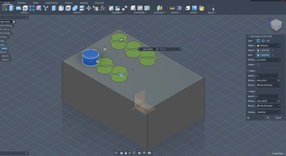
The first rectangular pattern I configured had Quantity 1 = 2 along X and Quantity 2 = 3 along Y, with Distance 2 left at 0 mm. Fusion happily generated 6 instances stacked on top of each other in Y, which read visually as 2 columns and not the 3×2 grid I wanted. Lesson: check Quantity AND Distance for both axes before clicking OK; an axis with quantity > 1 and distance 0 is a hidden error.
tab: 3. Asymmetric tubes
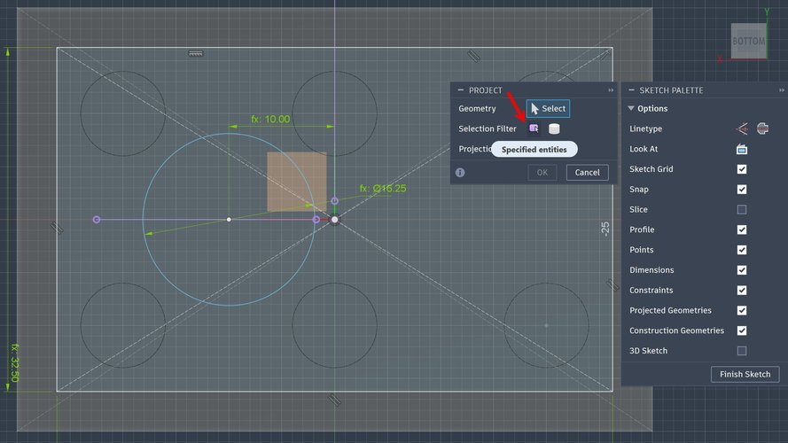
Same dimensioning issue as the studs: when I dimensioned the first tube center against the wall of the block instead of against the origin, the centers ended up at (-20, 0) and (0, 0) instead of the symmetric (-10, 0) and (+10, 0). The fix needed two things: project the X and Y axes into the sketch (Project / Include → Project, with Selection Filter set to Specified entities), and dimension the circle centre against the projected axes (purple lines).
tab: 4. Hollow body — and why I undid it
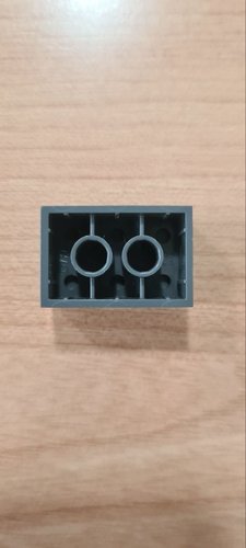
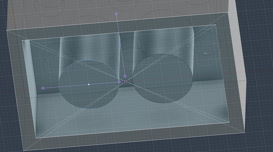
I first built the brick with the proper LEGO interior: a centred rectangle cut on the bottom face to a depth of block_z - wall_t, then two solid cylinders re-extruded as the inner tubes. Order matters here — the cavity must be cut before the tubes are added, otherwise the tube cylinders are deleted by the cut.
Later, when I started building the wax mould around this brick, the inner cavity and tubes started causing trouble: every Boolean subtraction of the brick from the wax block dragged those features into the cavity walls, and the milling later would not be able to reach into a Ø9.6 mm tube 16 mm deep with the available R0.5 tapered ball end mill anyway. Decision: for spiral 1 I cast a solid brick. The inner cavity and tubes were removed from the brick body before exporting the STL for the mould. Spiral 2 (a hollow brick faithful to a real LEGO) is left for the future, conditioned on a longer-reach ball end mill being available at the lab.
tab: 5. Chamfers — only on the studs
Applied chamfer_stud = 0.6 mm on the top edge of each stud (six chamfers). I did not chamfer the outer edges of the brick, because a real LEGO does not have those chamfers and I wanted the cast to read as LEGO-like. The stud-top chamfers do double duty: they soften the demoulding from silicone and they give the tapered ball end mill a curved/inclined surface to work on during the finishing pass, which is what the assignment expects.
tab: end
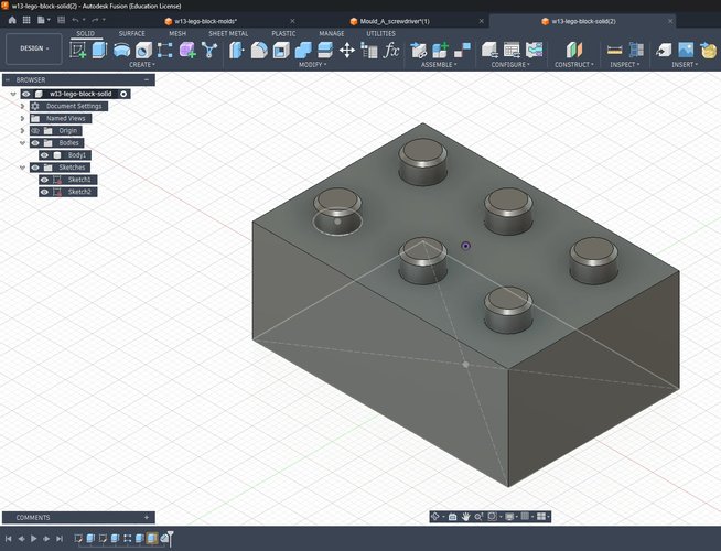
mould modelling — pivot to Tinkercad.
After spending several hours trying to close the mould model in Fusion 360 without getting a clean result, Nuria suggested switching to Tinkercad for the sake of time. Tinkercad’s boolean workflow with hole/solid primitives is well suited for this kind of two-half mould, and it let me close the model in a single sit-down session at the lab.
I imported the brick STL exported from Fusion as a solid and built the mould around it. The basic logic of the build:
- Split the brick volume into two halves with a horizontal plane through its mid-height. Each half becomes the cavity of one mould piece.
- Add inclined outer walls around the brick. The slope is there to help the milling tool reach the cavity walls cleanly — vertical walls would have forced more aggressive toolpaths and longer machining times.
- Place four alignment pegs (two per side) on the parting line. Two stick out as positives on one half, the other two as holes on the matching half. They keep the two pieces in register when the silicone is poured and when the cast is closed.
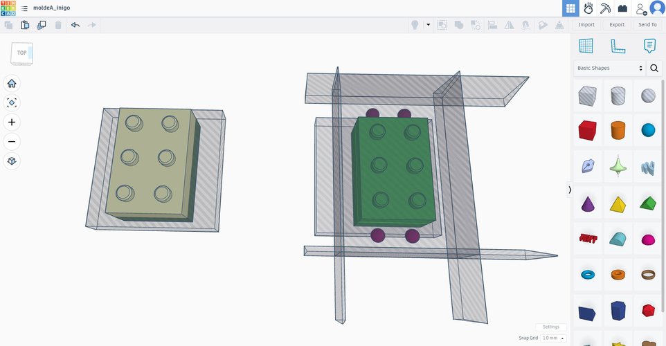
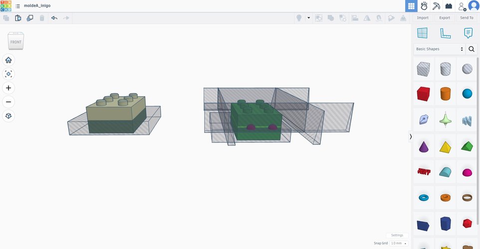
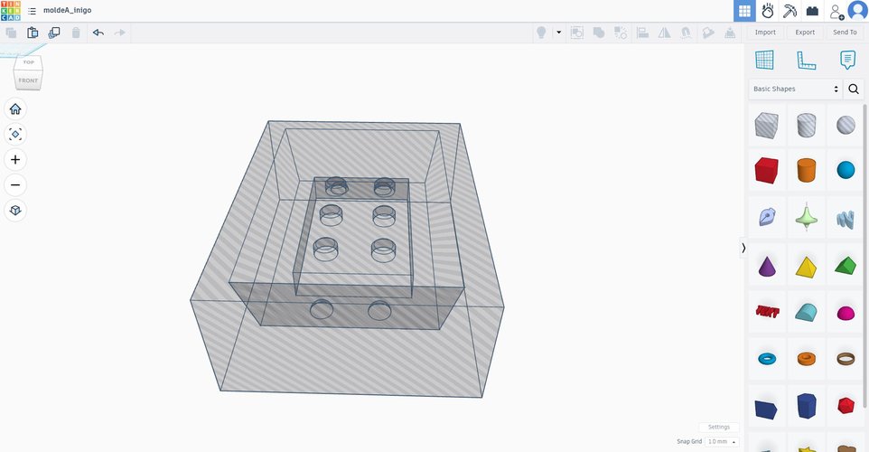
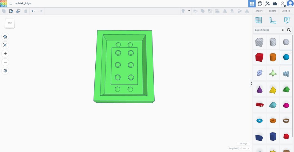
A couple of honest notes on this part of the week:
- The Fusion attempt was not wasted time, but it did burn hours that I should have cut shorter. Tinkercad solved this in well under an hour with Nuria sitting next to me, mostly because the tool stays out of the way and the boolean logic is direct: hole, solid, group, done.
- The mould geometry is intentionally simple. Spiral 1 is the solid brick, so the cavity has no internal tubes. Spiral 2 (a brick with the underside tubes a real LEGO has) would need a longer R0.5 ball-end mill that I still have to confirm is available at Fab Lab León before committing to that geometry.
Important — what actually went to the mill: the Tinkercad mould (the two negative halves) was modelled but not milled this week. After thinking through the toolpath constraints with Nuria, I pivoted to a simpler workflow: mill the brick itself in wax as a master, pour silicone over that wax master to obtain the negative mould, and then cast plaster in the silicone. The two-half negative-mould-in-wax route is parked for a later spiral. The Tinkercad work documented above is kept here because the modelling itself was done — and because the geometric reasoning (parting plane, alignment pegs, ramped walls) carries over to whichever route I take in the future.
toolpath generation in Mods.
With the brick STL (the master, exported from Fusion) loaded in Mods, the next step is generating the milling toolpaths. The lab uses Mods (modsproject.org) for this. Mods is browser-based, modular, and the workflow is built by wiring together small “modules” on a canvas. The result is a .nc G-code file that drives the Roland MDX-20.
selecting the program.
In the Mods home screen, search for wax in the program catalogue. The matching entry is mill 3D wax under the Roland MDX / iModela family. Selecting it loads a complete workflow on the canvas with two parallel branches preconfigured: one for the rough pass and one for the finish pass. Each branch carries its own parameters and feeds into a final controller module.
Quirk worth noting: to delete a module in Mods you have to click on the magenta title bar at the top of the module — not anywhere else on its body — and then choose Delete from the menu that appears. It took me a couple of misclicks to find this.
swapping the controller from TinyG to Roland MDX.
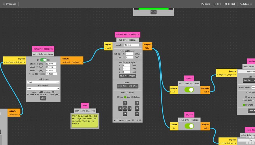
By default the program ends in a TinyG controller module, which is a generic CNC controller, not the machine we have. The MDX-20 needs its own module. The fix is mechanical:
- Delete the TinyG module (magenta title bar → Delete).
- From the right-hand modules panel, search
mode— the Roland MDX-iModela module shows up under the precision mill category. - Drag the Roland module onto the canvas where TinyG used to be.
- Reconnect the wires: the
pathoutput from the previous toolpath generator goes into the input of the Roland module, and the Roland module’s output goes to the two on/off modules that were already there. - Set the model to MDX-20, cut speed to 4 mm/s, jog Z to 2 mm, and absolute origin to
(2, 2, 0).

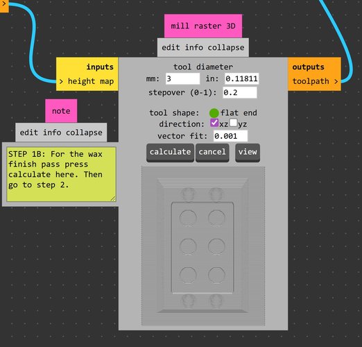
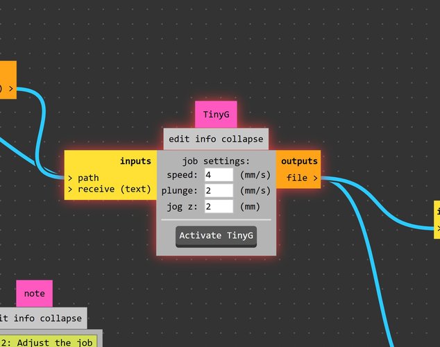
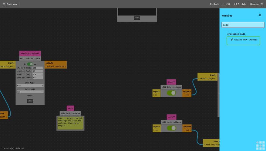
a small thing that catches you out.
When loading the STL into the workflow, the rough/finish toggle has to be set to finish (or rough, but at least one of them) before pressing calculate. If neither is selected, Mods accepts the STL but the toolpath preview never renders when calculate is pressed — the canvas stays empty and no error is shown. Easy to miss, easy to fix once you know.
a real bug in the Mods source code.
While generating toolpaths I noticed something off in how the rough pass was being computed. Tracing it back through the Mods Community Edition repo on the Fab Academy GitLab led me to modules/processes/mill raster/2.5D.js, where Francisco Sánchez Arroyo (The Beach Lab, current maintainer of Mods Community Edition) had already pushed a fix in this commit.
The actual bug was in one character: mod.toolpath.legnth instead of length inside the splice call. As Francisco explains in the commit message, that typo meant every completed layer was prepended instead of appended, so the rough pass was effectively producing the cut order bottom-up instead of top-down. The end mill was being told to start from the deepest layer first, which is exactly the kind of behaviour you do not want from a roughing strategy. While at it, the same commit renames the path-order radio labels from the old forward / reverse to the much clearer outside-in / inside-out, keeping the internal IDs intact so that previously saved Mods programs still load correctly.
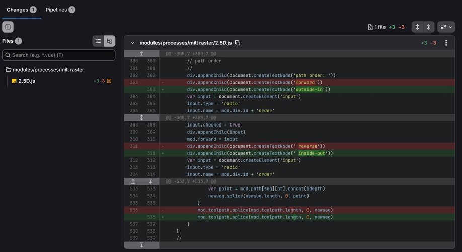
modules/processes/mill raster/2.5D.js. The character-level typo on mod.toolpath.legnth caused every completed layer to be prepended instead of appended — producing a bottom-up cut order in the rough pass. The same commit relabels the path-order radio buttons from forward / reverse to outside-in / inside-out.Worth documenting because it is a textbook example of a one-character typo with a fully functional consequence: not only was the UI confusing (forward / reverse told you nothing about what the mill would actually do), the bug it was hiding was reordering the cut layers in a way that could damage the stock or the tool. Fixing the typo and relabelling the UI in the same patch is the right move.
parameters in use.
| Parameter | Value | Note |
|---|---|---|
| Wax block | 146 × 90 × 34 mm | Ferris File-A-Wax Blue |
| Stock for this run | 69 × 89.976 × 16.974 mm | Half-thickness in Z — see note below |
| Tool | 3 mm flat end mill | Shared with Fab Lab León toolset |
| Cut speed | 4 mm/s | Conservative starting point for wax |
| Stepover | 0.2 (ratio) | = 0.6 mm between raster lines |
| Direction | xz (final run) | First finish attempt was xy — see fabrication notes |
| Passes | rough + finish | Both run, in that order |
| Estimated time (finish) | ~23 min | Mods reported 00:23:07 for the finish pass |
A note on the Z = 16.974 mm figure: the wax block is 34 mm thick in total, but the job was set up with stock Z at half that, the idea being that two masters could be milled from the same block — one master per half of the original two-half mould plan. In practice only the first master was machined; the second half was never started, so the bottom ~17 mm of the block stayed untouched and is still available for a future run.
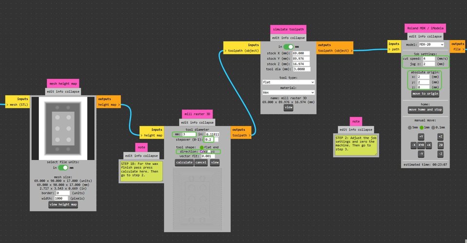
mesh height map → mill raster 3D (3 mm flat, stepover 0.2, direction xz) → simulate toolpath → Roland MDX-iModela on MDX-20. Estimated time 00:23:07.the curved-surface requirement.
Pablo reminded me on Monday that the part should have at least one tilted or curved surface, otherwise the milling collapses into a 2.5D job and the finishing pass with the ball-nose endmill has nothing to do.
The 2026 evaluation page for Moulding & Casting asks the student to “design a small object with at least a flat back side, where the front presents some details and a smooth surface finish that does not show production process”. The piece does not have to be primarily curved, but it does need detail on its front face that justifies the finishing pass with the ball-nose endmill — otherwise a flat endmill alone would close the work.
In my brick, the chamfers on the top edges of the 6 studs count as small inclined surfaces that the tapered ball-nose endmill will detail in the finishing pass. The rest of the brick uses sharp edges to preserve the LEGO visual language. I will verify with Nuria that this is enough; if not, I’ll add a slight fillet at the top of one stud or dome a single stud so the tapered ball-nose tool is more clearly justified.
why this brick is not too small for the available stock.
The wax stock is 146 × 90 × 34 mm. The strategy is to mill both halves of the mould side by side on the same wax block (David Fernández’s approach in his Week 14). With a 15 mm side margin and a 10 mm separation between moulds, the X requirement becomes:
2 × 48 + 10 + 2 × 15 = 136 mm — fits in the 146 mm of stock with 10 mm to spare.
32 + 2 × 15 = 62 mm in Y — fits in 90 mm with 28 mm to spare.
19.2 / 2 + 5 + 5 = 19.6 mm of milling depth — fits in the 34 mm of stock with 14 mm to spare.
This is why I dropped from scale = 2.5 to scale = 2: at 2.5 the X requirement was 160 mm, which did not fit in the 146 mm wax block. Lesson: measure the actual stock before locking the scale, the nominal inches ≠ the milled stock.
Note: this calculation belongs to the original two-half-mould plan that was later parked. With the master-in-wax pivot the actual milled layout is a single brick of 48 × 32 × 19.2 mm sitting on top of a half-thickness slab of wax — much more comfortable than the plan above. The reasoning is kept here because it explains why
scale = 2was the right call regardless of the route taken later.
individual assignment — fabrication.
The plan was originally split in two parallel tracks (Track A: wax-milled negative mould → silicone → plaster cast; Track B: PLA-printed master → silicone over PLA → plaster cast). Halfway through the week the lab track pivoted: instead of milling the two halves of the negative mould in wax, we milled the brick itself in wax as a master, and the silicone will be poured over that wax master to obtain the negative mould. Reasons for the pivot are explained in the mould modelling — pivot to Tinkercad subsection above.
The fabrication workflow this week becomes:
Track A — wax-milled master (lab):
- Brick STL exported from Fusion 360 (the same parametric brick documented above, with the inner cavity and tubes already removed).
- Toolpath generated in Mods with the Roland MDX-iModela module — see the toolpath generation in Mods subsection above for the parameters.
- CNC milling of the brick on the Roland MDX-20: rough pass, then finish pass.
- Silicone pour over the wax master — RPRO 30, 1:1 by weight, 40 min working time. (Pending.)
- Cast in Algaplay Michelangelo Casting Plaster (synthetic resin powder mixed with water at 1 kg : 0.30 l, 10–12 min working time, demould 20–40 min after pouring). (Pending.)
Track B — PLA-printed master (home):
- Print the brick in PLA on the Bambu Lab A1 at home, with fine layer height (0.08–0.12 mm) to minimise layer-line visibility from the start.
- Post-process the print: sanding, primer (filler primer if needed), paint or polish until the surface no longer shows the production process.
- Silicone pour over the post-processed PLA master.
- Cast in Algaplay Michelangelo — same material as Track A, so the comparison is between the two masters (wax-milled vs PLA-postprocessed) and the silicone moulds they produce, not between cast materials.
The comparison between Track A and Track B feeds the “compare printing vs milling” requirement of the group assignment, with the caveat that both tracks now produce a master rather than a negative mould — the comparison shifts accordingly.
Note on solid vs hollow cast (spiral approach): the LEGO geometry has an open cavity with two internal tubes on the bottom face. Reproducing those tubes faithfully would require, in the negative-mould route, a male plug machined from wax that the tapered R0.5 endmill cannot reach into a Ø9.6 mm internal tube space (the cone widens up to ~9.6 mm at the required 16 mm depth). For both routes (negative mould and master) spiral 1 keeps the simplified solid geometry — no inner cavity, no tubes. Spiral 2 (future): revisit this once Fab Lab León confirms the availability of a longer-reach R0.5 endmill or a thin straight endmill able to mill the inner geometry.
Note on mould wall geometry (Nuria, local class Apr 27): when the negative-mould route is eventually attempted, the side walls of the wax mould — the slope from the outer edge of the wax block down to the cavity contour — should not be vertical. They should be ramped/inclined for two reasons: (a) the tapered ball-nose endmill reaches the bottom of the mould without the cone-shaped shank colliding against vertical walls, which improves finish; (b) the cured silicone releases more cleanly from a ramped wax wall than from a sharp vertical edge. This is distinct from the draft angle on the master that I decided to skip (the master keeps LEGO-like vertical walls and demoulds fine in Shore 30 silicone). The 10° draft applied in Tinkercad to the 4 rectangular side walls of each negative-mould cavity is preserved in the saved Tinkercad file for whenever that route is reactivated.
tooling.
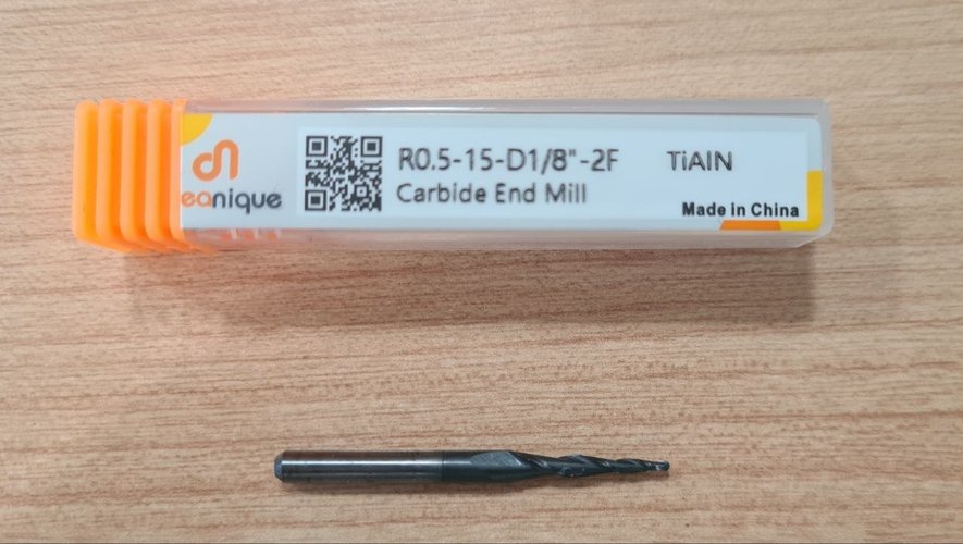
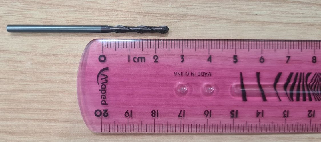
Two endmills available:
| Endmill | Code | Geometry | Use |
|---|---|---|---|
| Tapered ball-nose | R0.5-15-D1/8”-2F (Dreanique, TiAlN coated) | R0.5 mm tip, 15° taper, 1/8” shank, 2 flutes | Finishing — parallel pass on tilted surfaces and chamfers |
| Flat endmill | 3 mm Ø, 25 mm flute length | Cylindrical, 2 flutes | Roughing — adaptive clearing of the bulk material |
The R0.5 tapered ball-nose has a tip diameter of ~1 mm and the cone widens at 15° per side, which limits how deep it can plunge with a fine feature width. The flat 3 mm endmill is the workhorse for removing material; the tapered endmill only kicks in for the finishing pass on the tilted/curved surfaces.
wax milling — what actually happened.
Three milling runs in sequence on the Roland MDX-20: one rough, two finish attempts (XY first, then XZ). Each one taught me something different and each one left the master in a visibly different state, which is why the photos are split into stages instead of just showing the end result.
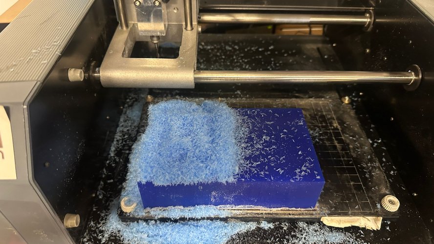
Rough pass (3 mm flat endmill, 3 mm layer height). The plan was a standard adaptive clearing: the mill descends 3 mm per layer and clears the bulk of material around the brick, contour by contour. While the rough was running the wax stock looked like this — the end mill working, blue chips piling up around it:
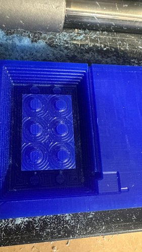
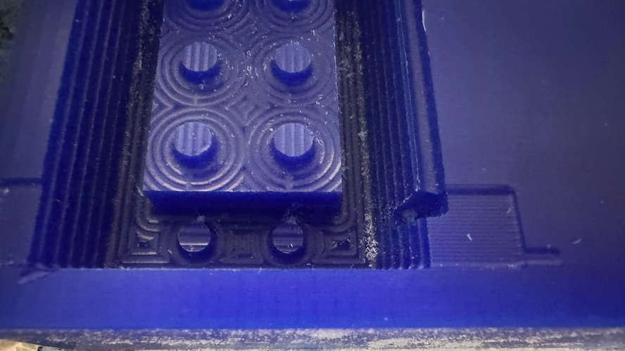
Two issues showed up during the rough pass:
- The brick was not sitting on the base of the wax stock. In Mods I had given the brick a small Z offset above the stock floor (the master needs a small flange of wax around the base, otherwise there is no surface to hold the silicone dam later on). At a certain point during the rough pass the mill ended up cutting at a Z above where any wax remained — cutting in mid-air, literally working in empty space. The toolpath was technically correct given the input, but the assumption “everything below the brick contour is solid wax” did not hold near the perimeter once the rough had already removed material there.
- The bug fixed by Francisco’s commit on
2.5D.js(see a real bug in the Mods source code above) was relevant here: the rough pass relies on the order in which completed layers are added to the toolpath, and a bottom-up cut order is exactly the kind of thing that turns a cutting-in-mid-air situation into a tool-collision situation in the wrong scenario.
Finish pass — first attempt (3 mm flat endmill, direction XY). With the rough done I ran the finish pass in the XY plane first. With direction XY, Mods generates raster lines in the horizontal plane and the mill descends to the depth of each contour. One thing caught me off-guard during the descent: the 3 mm flat endmill has 25 mm of flute length, and once the toolpath asks for a Z that puts the tip at the bottom of the part, the mill plunges all 25 mm in one go and proceeds from there. There was no actual collision — the wax is shallower than the flute — but the descent behaviour was alarming the first time and not what I had expected. The pass itself ran fine: the master came out with visible raster marks on the brick top and around the studs, a clear improvement over the rough state.
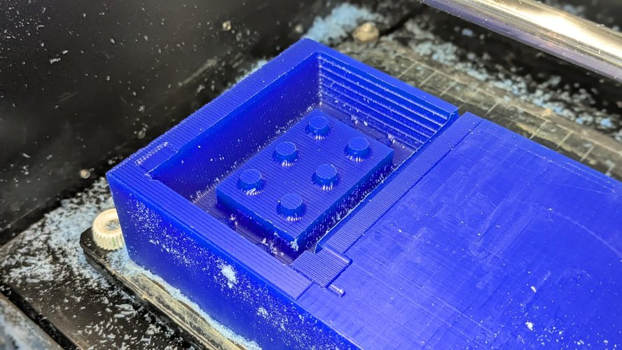
A note on stepover: I left it at 0.2 (= 0.6 mm between raster lines for the 3 mm endmill), which is what you can see on the master. Dropping to 0.1 (0.3 mm between lines) would have produced a more polished surface but would have roughly doubled the milling time. For a master that will be covered in silicone anyway — the silicone fills the raster valleys and the resulting mould reads as smooth — 0.2 is enough.
The Mods Simulate: mill raster 3D tab gives a useful preview of what the toolpath will do before running it. For this XY pass the simulation looked like this:
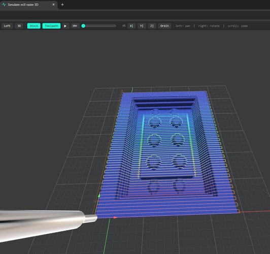
Simulate: mill raster 3D view of the finish pass in the XY plane. Raster lines wrap the brick contour and the six studs at successive heights, coloured from blue (lower Z) to red (upper Z). The 3 mm flat endmill is rendered in the foreground.Finish pass — second attempt (3 mm flat endmill, direction XZ). Switched the raster direction from XY to XZ. Now the raster lines run along X while Z varies, which is the right strategy for finishing the side walls of the part — the XY pass had concentrated on the horizontal surfaces (brick top and around the studs), and the XZ pass complements it by working the vertical ones. This is the run that gave the side walls of the master their final pass.
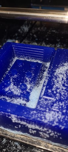
Studs not fully detailed. The 3 mm flat endmill cannot enter spaces where the gap between the stud and the surrounding wax wall is narrower than 3 mm. With my brick (stud_d = 6.4 mm, stud-to-brick-edge margin under 3 mm at the corner studs), the result is that the four corner studs were not fully detailed: the mill could not get all the way around their base. The two central studs came out cleaner. This is a tooling limitation, not a CAM error — a smaller-diameter endmill, or the tapered R0.5 ball-nose, would close the gap in a future spiral.
The final state of the master after rough + finish XY + finish XZ shows three clearly distinct surface zones: the stepped scallops of the rough pass on the side walls (3 mm layer height), the finer ridges of the finish XZ pass on the top face and around the studs, and the flat unmilled areas around the corner studs where neither pass reached:
preparing the master for the silicone pour.
Once the milling was done, the master needed three things before any silicone could be poured: removal from the machine, surface preparation, and manual finishing of the corners that the 3 mm endmill could not reach.
The wax block was attached to the MDX-20 bed with double-sided tape, so the first step was simply lifting it off the bed. The block came up clean, with the master intact on top of the unmilled stock around it.
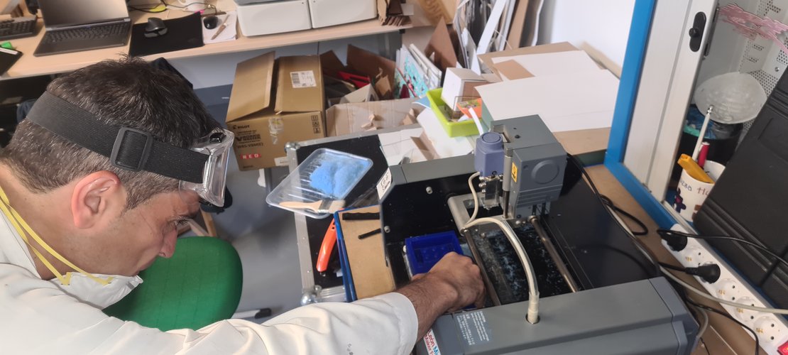
With the surface clean, Smooth-On Universal Mold Release went on next. The release agent serves two purposes here: it makes demoulding the cured silicone easier later, and — perhaps more importantly for the cutter step that follows — it lubricates the wax surface so the manual cleanup of the corner studs is less likely to tear out chunks of the master.
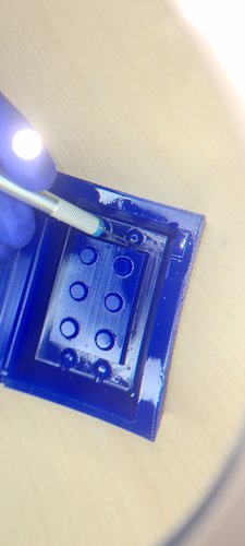
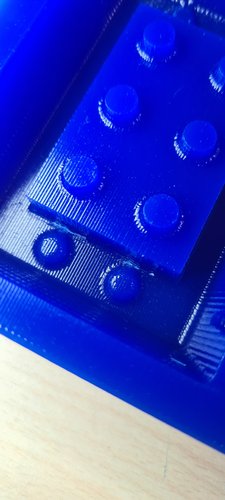
The corner studs were the part that needed manual finishing. As documented in the milling section, the 3 mm flat endmill cannot fit fully between the corner studs and the surrounding wax wall, so those studs were left partially undefined. Under a small LED lamp, I worked each corner stud with a precision cutter to bring its profile closer to the design.
measuring the cavity volume.
Before mixing any silicone, I needed to know how much was actually required to fill the cavity around the master. The simplest way to find this without trusting CAD numbers is to fill the cavity with water and weigh it — water is close to 1 g/ml, so the mass in grams is also the volume in millilitres.
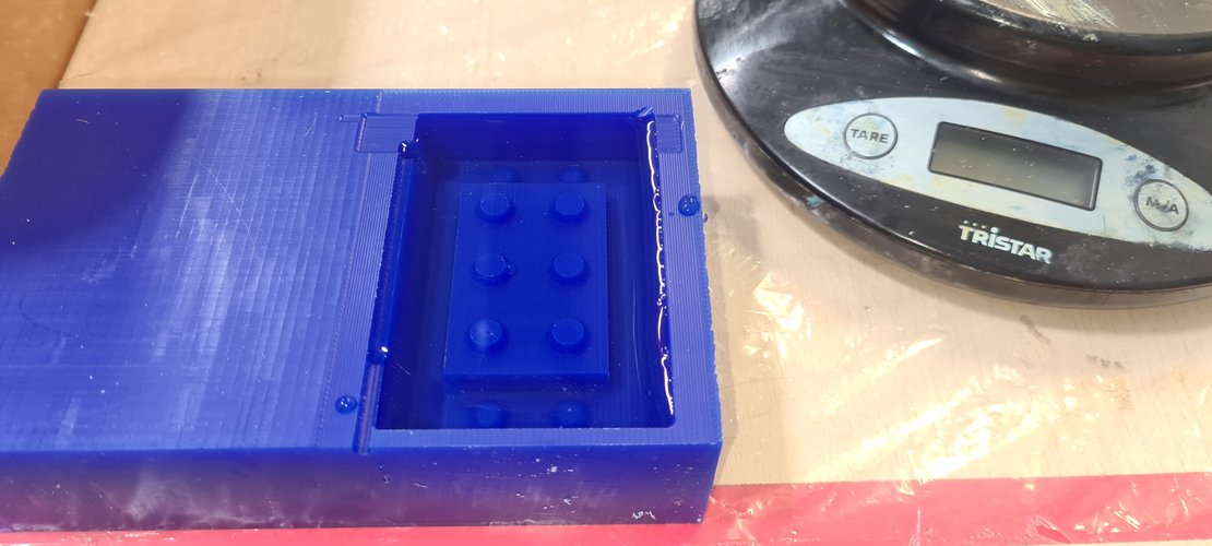
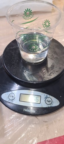
The cavity took ~56 g of water, which translates to ~56 ml of silicone needed. With the 1:1 mix ratio of RPRO 30 (Base A + Hardener B by weight), I rounded up to 30 g of A + 30 g of B = 60 g total, giving a small ~7% margin to ensure the cavity fills completely without running out mid-pour.
silicone test mix.
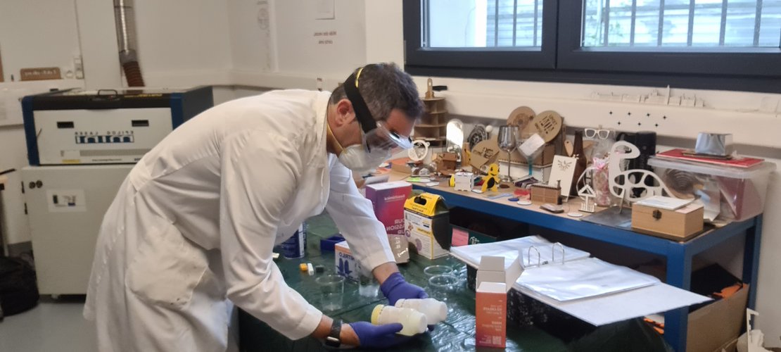
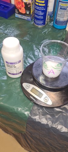
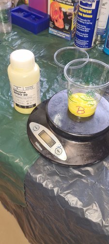
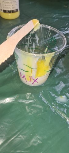
Before committing the real mix, Nuria recommended doing a small test mix to check that the catalysed silicone behaves as expected — sets in roughly the stated time, no obvious surface issues, no mismatched batches. The test was small (a few grams of each component) and went into a separate cup, marked MIX, away from the master.
plaster test mix.
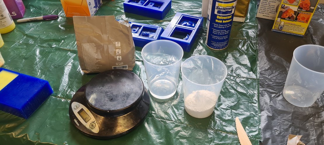
While the silicone test cured, I also did a test mix of the Algaplay Michelangelo plaster to verify the water-to-powder ratio and the working time before committing to the real cast. The bag specifies 1000 g of powder to 300 ml of water with a 15-minute setting time; for the test I scaled this down to roughly the proportions needed for a single brick cavity.
silicone pour over the wax master.
With both test mixes confirmed and the master prepared, I mixed the real silicone — 30 g of A + 30 g of B, by weight on the same Tristar kitchen scale — and stirred until the colour was uniform white-yellow, no streaks. The pour itself was a single slow motion from one corner of the cavity, letting the silicone find its own way around the master without trapping air against the studs.
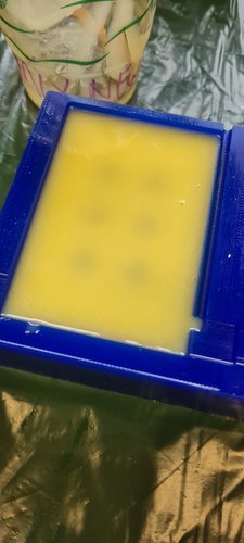
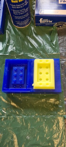
The silicone cured undisturbed for the full 3-hour setting time. Once cured, demoulding was straightforward — the release agent did its job and the wax master came out of the silicone cleanly, without tearing or sticking. The silicone mould came out with the cavity faithfully reproduced, including the six stud holes.
plaster cast in the silicone mould.
The plaster mix was scaled to one tenth of the bag instructions: 100 g of powder + 30 ml of water, mixed for ~2 minutes until smooth. With a 15-minute setting time the working window was tight but manageable, and the silicone mould — small and open-topped — was easy to fill in a single pour.
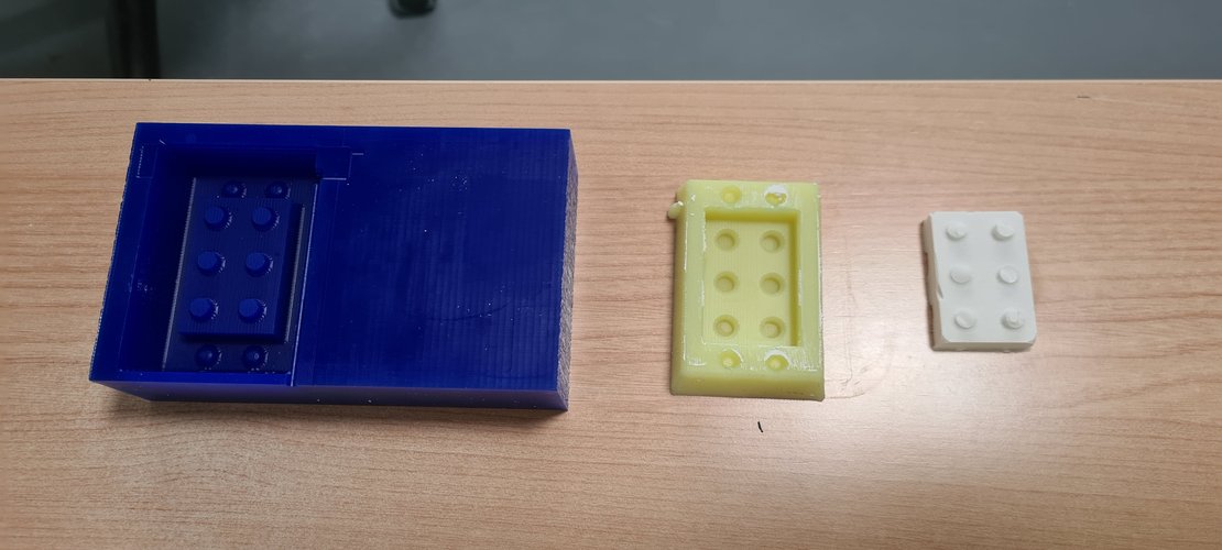
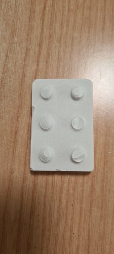
The cast came out dimensionally faithful to the master: the brick footprint, height and stud spacing all matched the wax original very closely. But the studs themselves came out with incomplete fill: a couple of them are noticeably shorter than they should be, and one or two are partially absent at the tip. The cause is almost certainly air trapped in the bottom of the cylindrical stud holes — the plaster runs down and seals the top of each hole before the air at the bottom can escape, leaving voids exactly where you don’t want them.
track B — FDM PLA route, parallel attempt.
In parallel with the wax route, I am running a second master through the same silicone-and-plaster pipeline, this time 3D-printed in PLA on the Bambu Lab A1. The goal is a direct side-by-side comparison of the two routes at the end of the assignment: the same brick geometry going into the same silicone, with only the master fabrication route changing.
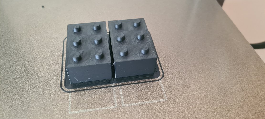
Initial print attempts. Before committing to the final master, I printed two copies of the brick to validate the geometry on the printer and check the visual quality of the FDM surface. These were standard-quality prints in black PLA — useful as a reference for what the layer texture looks like before any post-processing, and a clear motivation for why the master needs a coating step before the silicone pour.
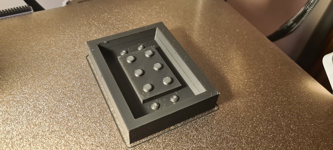
Final master print. The actual master used for Track B is a different print: a single half-brick master with the casting box built into the same part, in black PLA, optimised for surface quality. Slicer settings:
- Layer height: 0.2 mm.
- Top surface: ironing enabled, to flatten the brick’s top face.
- Walls: more wall loops than default, for a denser shell on the visible faces.
- Infill: higher than default, since dimensional stability matters for the master.
- Print time: 4 h 25 min, unattended on the Bambu A1.
Designing the casting box and the master as a single integrated print is a small process improvement over Track A. In Track A the cavity walls came from the unmilled wax surrounding the master — usable but ad-hoc. In Track B the box is part of the design itself, so its dimensions, wall thickness, and inner offset around the master are all controlled in CAD rather than left to chance.
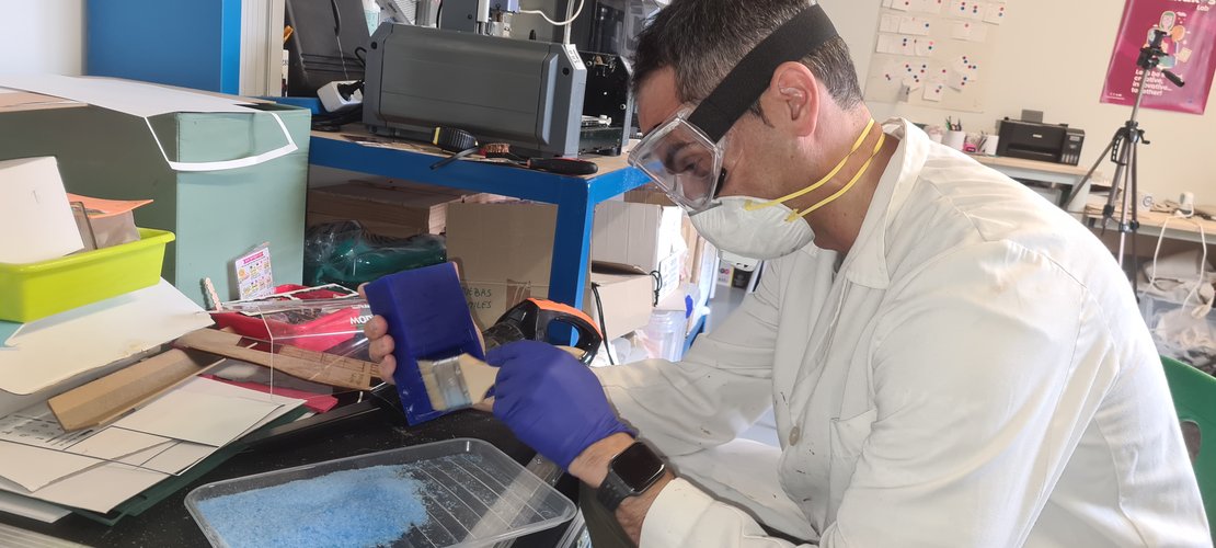
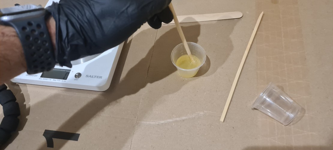
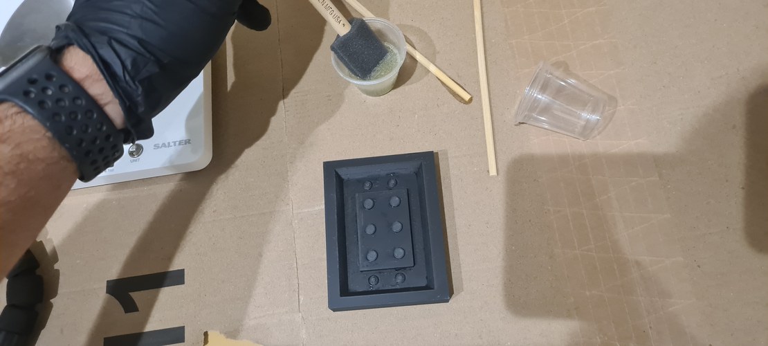
XTC-3D coating applied. With the master printed, I moved on to the surface coating. XTC-3D is a two-part epoxy, so the first step is weighing and mixing parts A and B — 2A : 1B by volume (100A : 42B by weight) — in a plastic cup on the kitchen scale and stirring for at least a minute until uniform. Nitrile gloves throughout, since this is the one sensitising material of the week. I then brushed the mixed epoxy onto the master with a foam brush, which lays down a thinner, more even film than a bristle brush and is cheap enough to discard after the short ~10 min pot life. The freshly coated master came out wet and glossy, the epoxy flowing into the layer striations — exactly the effect the coating is meant to produce. It is now curing (~2 h to tack-free, ~3.5 h for a full thin-layer cure) before the release agent and the silicone pour.
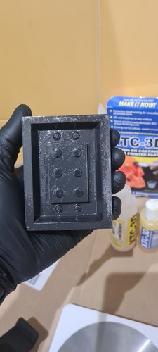
Wet-sanding the cured coating. After about a day of curing, I knocked the XTC-3D back with a light wet-sand — 400 grit first, then 600 — keeping both the paper and the part wet throughout so the slurry washes away and the abrasive does not clog. I worked the flat faces and stayed light over the studs and their chamfers so the detail would not round over. This is where the actual smoothing happens: the coating fills the layer valleys, and the sanding evens out the surface and any drips left by the brush. The wet-sand replaces the wet gloss of the coating step with a matte finish — that is fine here, because what the silicone needs is even geometry, not shine. The part is now dried completely, ready for the release agent.
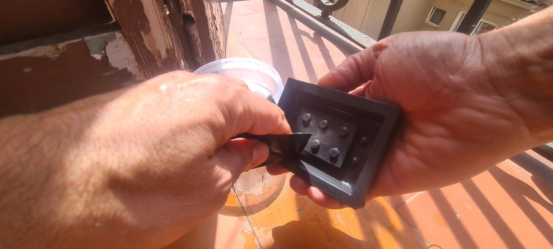
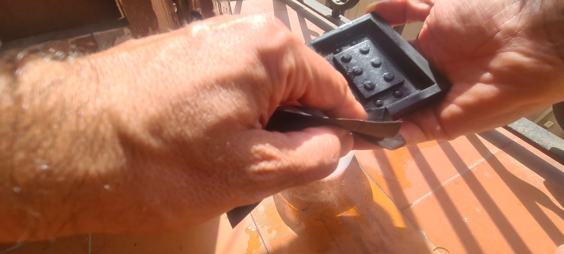
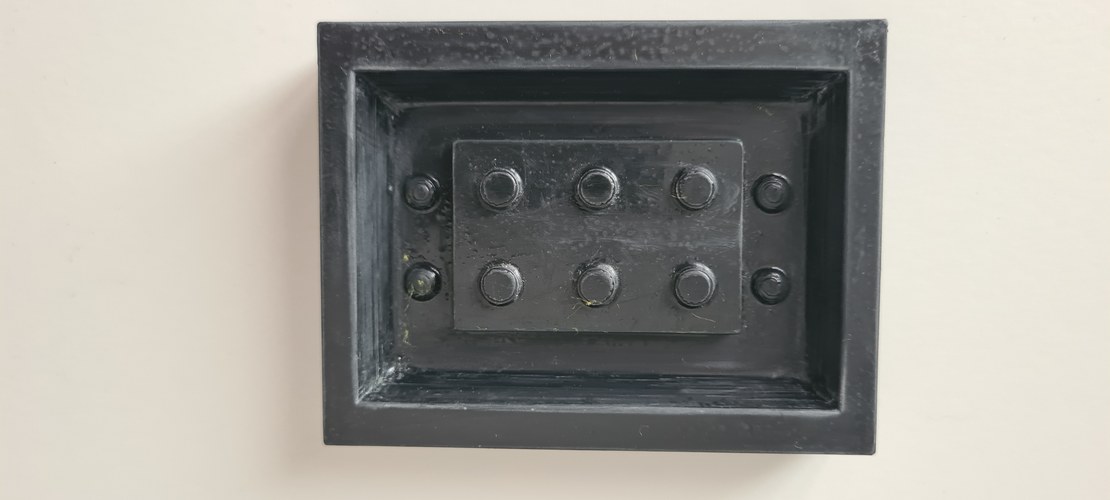
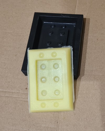
Silicone demoulded, plaster poured. The RPRO 30 cured and the silicone came away from the master cleanly — the brick cavity, the six stud holes and the corner witness studs all transferred sharply, so the XTC-3D coating and wet-sand prep paid off. I then cast the same Algaplay Michelangelo plaster as in Track A, with the same mix and procedure (no need to repeat it here), but this time taking Adrián’s and Pablo’s advice: first packing plaster into each stud hole with a wooden skewer, then filling the rest of the mould slowly with it slightly tilted, so air could escape instead of getting trapped in the upward stud cavities — the exact failure mode that left the Track A studs incomplete. The cast is setting now.
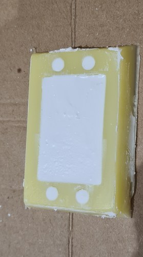
milling vs printing.
With both plaster casts in hand — one from the wax-milled master (Track A), one from the FDM-printed PLA master (Track B) — the side-by-side is the actual point of the week: comparing milling and 3D printing as two routes to the same cast.
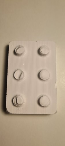
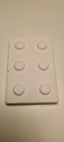
Surface finish. The clearest difference is the surface, and it goes the opposite way to what I expected. The Track B cast (print route) is cleaner: no visible lines on the flat face and none radiating around the studs. The Track A cast (wax route) carries the milling raster — fine parallel lines across the whole face and a sunburst of toolpath marks around each stud — reproduced faithfully from the wax master through the silicone into the plaster. The counterintuitive part is that FDM normally leaves coarser surface artefacts than milling, but here the XTC-3D coating plus the 400→600 wet-sand erased the layer lines on the printed master, while the milled wax kept its toolpath texture untouched. So the finishing step, not the base process, decided the surface quality.
Studs and trapped air. This is where the pour technique shows. The Track A studs came out incomplete — short, with torn or missing tips — the trapped-air failure mode from pouring into upward-pointing cavities with no pre-wet or tilt. The Track B studs filled cleanly: Adrián’s pre-wet (packing each stud hole with a skewer) and Pablo’s tilted slow pour worked, with none of the voids that spoiled Track A. The techniques that were only a plan last session are now confirmed in practice.
Depth / dimensional note. The Track B relief is visibly shallower than Track A. That is a depth slip in the printed master, not something the moulding process did — a dimension I got wrong in the Track B model. It does not change the finish comparison, but it is worth flagging as an honest fidelity difference between the two masters.
Effort, and what each route is good at. Both routes reached a usable silicone mould and plaster cast, with different kinds of work along the way. Milling (subtractive, in wax) is fast to a solid master and the wax is reusable, but the ball-end tool leaves a raster that needs finishing and small features hit the tool-diameter limit — the corner studs needed manual cutter cleanup. Printing (additive, in PLA) places small features without a tool-diameter constraint and let me build the casting box into the same part in CAD, but it needs the extra chain of coating, sanding and release agent to get a clean, silicone-ready surface. For this geometry — a small brick with deep, fine studs — the print route plus the improved pour gave the cleaner cast with complete studs, which is the result I would carry forward.
reflections.
The biggest lesson of the week, the one I want to put first: when spatial reasoning fails in CAD, go back to orthographic views on paper.
Halfway through the modeling I got stuck. I could not picture in my head what the mould geometry would look like in Fusion — the relationship between the brick, the cavity walls, the offsets, the stud heights inside a wax block — and the more I tried to model it directly, the more frustrated I got. That frustration is what eventually led to the pivot to Tinkercad with Nuria’s help: a workable but not satisfying outcome, because the model that finally worked was not the one I had set out to build.
When I got home that evening, I stopped trying to model and went back to the basics of technical drawing: top view, front view, side view, dimensioned by hand, on a dotted notebook page. The moment I started laying out the dimensions on paper — LEGO width + 2× safety + 2× recess + 2× wall = 32 + 2×6 + 2×5 + 2×3 + 2×5 = 70 mm, wax_z = 34 mm, block_z = 19.2 mm, 34 - 23.4 = 10.6 mm — my head clicked. I could see how the geometry would have lived in the Fusion sketches all along.
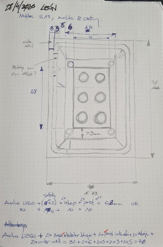
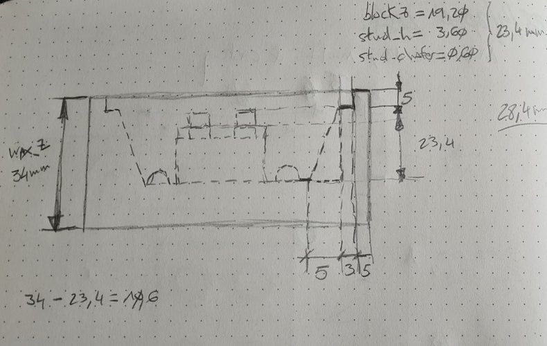
The lesson is concrete: had I drawn these views before sitting down with Fusion, the modeling session would have gone much better. When spatial visualisation is not your strongest skill, paper sketches with explicit dimensions are not a regression — they are the right tool for the job, and they save time rather than waste it.
The rest of the lessons, in roughly the order they occurred:
The second is that a parametric model rewards the time it takes to set up. I changed the global scale three times during the design (3, 2.5, 2) and once the scale changed, every other dimension followed automatically — including chamfers, stud and tube geometry, all through the scale chain. Without the parameters, each scale change would have meant rebuilding the model.
The third is that Fusion’s dimensioning tool is sensitive to how you click. When you dimension a point against another point, Fusion infers horizontal/vertical/diagonal from the position you place the dimension witness, not from the order of your clicks. I lost an hour to this with the studs and another half hour with the tubes. The fix was to project the X and Y axes into the sketch (with Selection Filter set to Specified entities) and dimension circle centres against the axes, not against the origin point.
The fourth is that the wax stock dimensions drive the design, not the other way around. The brick was originally designed at scale 2.5 (60 × 40 × 24 mm), which fit in the stock as a single piece but did not fit as two side-by-side mould halves — the X requirement (160 mm) exceeded the 146 mm of available wax. Bringing scale down to 2 solved it without redesigning anything. Always measure the stock first; nominal “1-1/2 inch” ≠ 38.1 mm in real wax. The block I have is 34 mm, four millimetres less.
The fifth, more honest: I almost picked the wrong piece. The original idea was a silicone foot for the standing desk leg, and only after talking to Nuria did I realize that the silicone in the lab is for moulds, not for products. If I had gone ahead I would have wasted material and time discovering that the cast wouldn’t release. Worth checking material compatibility with the local instructor before committing — even when you think you have it figured out from the SDS.
The sixth, also honest: the master-in-wax pivot was not in the original plan. I started the week intending to mill the two halves of the negative mould directly in wax. Halfway through the week, after working through the toolpath constraints with Nuria and seeing how the rough pass behaved on the Roland MDX-20, the simpler route — mill the brick itself in wax, pour silicone on top, cast plaster in the silicone — won out. Both routes satisfy the assignment (an object cast in plaster, with a discussion of milling vs printing as fabrication strategies), but they are not the same piece of work. The Tinkercad mould is parked, not abandoned: the file exists, the geometry is clean, and a future spiral can pick it up.
The seventh: the silicone mould came out cleanly, but the plaster cast did not. The cured silicone reproduced the master faithfully — six well-defined stud holes in the cavity floor — and the wax demoulded without sticking. But the plaster cast that came out of that mould has visibly incomplete studs: a couple are short, one or two are missing material at the tip. The cause is the geometry itself working against me: the stud holes are deep cylindrical cavities pointing upwards during the pour, and when liquid plaster runs over the top of each hole it traps an air pocket at the bottom that has nowhere to escape.
After the cast came out, both Adrián and Pablo gave me concrete suggestions for next time. Adrián recommended pre-wetting the deep stud holes with a thin layer of plaster applied with a small brush or cotton swab before the main pour — that way each cylindrical pocket already has plaster wetting its walls and any trapped air has been displaced point by point, before the bulk pour can seal the top. Pablo suggested a different angle of attack: tilt the silicone mould during the pour and feed the plaster in slowly from one side, letting gravity fill each cylindrical pocket from the bottom up while air escapes from the still-uncovered side. Either technique alone would probably have helped; both together — pre-wet first, then tilted slow pour — should solve the problem entirely. The failure mode to remember: pouring into upward-pointing pockets without any pre-wetting or tilt strategy is asking for trapped air. The Track B cast confirmed it: with the pre-wet and tilt applied, the studs filled cleanly — none of the trapped-air voids that left the Track A studs short.
The eighth, on tooling: read the source code of the tools you use, even when you do not need to. The bug in mill raster/2.5D.js was not blocking my work — Francisco had already fixed it upstream — but tracing the rough-pass behaviour to that one-character typo in mod.toolpath.legnth was the most instructive moment of the week. CAM is not magic; it is JavaScript loops over toolpath arrays, and when the array is built in the wrong order the mill behaves accordingly.
design files.
The CAD source and the 3D-print meshes for the brick and the Track B master (the MDX-20 toolpaths are left out):
w13-lego-block-solid.f3d— Fusion 360 native source (the parametric brick/block).w13-lego-block-solid.stl— STL export of the solid block.week13-ego-brick-v01.stl— the 2×3 EGO brick on its own.modelA_inigo_final_version_optimized.stl— the final, print-optimised STL of the Track B part (master with its integrated casting box).moldeA_inigo.3mf— the slicer project used to print it.- Earlier STL iterations kept in the folder for history:
moldeA_inigo.stl,moldeA_inigo_V1.stl,moldeA_inigo_final_version.stl.
Material datasheets and safety data sheets (SDS), collected here as well as in the material tabs above so the evaluator has every file in one place:
- Ferris File-A-Wax Blue SDS — milling wax.
- Reschimica RPRO 30 SDS — mould-making silicone (Italian).
- Smooth-On XTC-3D SDS — brush-on epoxy coating (Track B).
- Reschimica R-Wax Release SDS (APDIST01) — wax-based release agent (Track B).
references.
- David Fernández — Fab Lab León 2025, Week 14: Moulding & Casting. Same lab, same wax (Ferris green), same general workflow. Main reference for the two-halves-on-one-block layout and the CAM strategy in Fusion.
- Adrián Torres — Fab Lab León 2020, Week 15: Moulding & Casting. Older but useful for the local lab conventions — water-based volume calculation, perimeter step around the part for easier silicone release.
- Fab Academy 2026 — Moulding & Casting evaluation page. Current assignment requirements.
- Reschimica RPRO 30 product page. Manufacturer reference for the silicone.
- Algaplay Michelangelo Casting Plaster. Manufacturer reference for the synthetic resin powder used as the cast material.
- Ferris File-A-Wax product page. Manufacturer reference for the wax.