Machine Design
weekly schedule.
| Time block | Wed | Thu | Fri | Sat | Sun | Mon | Tue | Wed |
|---|---|---|---|---|---|---|---|---|
| Global class | 3 h | |||||||
| Local class | 1,5 h | 1,5 h | ||||||
| Research | 1 h | 2 h | 1 h | |||||
| Design | ||||||||
| Fabrication | 4 h | 8 h | ||||||
| Documentation | 2 h | 1 h | ||||||
| Review |
overview.
This week is a bit different from the others: it is mostly a group assignment. The bulk of the technical documentation lives on the group page, and my individual page focuses on what I contributed personally.
The brief was to design and build a machine that makes something — mechanics, actuation, automation and a working end-effector. Our group went for a small lathe inspired by the 2015 italian Fab Academy students (Gianluca Pugliese, Enrico Bassi, Daniele Ingrassia), which themselves borrow heavily from the MIT MTM project (Machines That Make). The fit is natural — simple frame, mostly 3D-printed, CNC-style motion control — and it meant we could lean on a well-documented design instead of starting from zero.
The main group documentation — mechanics, CAD, full BOM, assembly and the machine actually doing something — lives here:
- Group page (Fab Lab León, 2026): https://fabacademy.org/2026/labs/leon/mtm/index.html
My individual contributions, documented on this page, were:
- Print-time study for all the 3D-printed parts of the lathe, to plan the production pipeline across the group’s printers.
- Printing several of those parts on my Bambu Lab A1 at home.
- Fusion 360 modelling of an Arduino UNO + CNC Shield enclosure, forked from David Fernández’s 2025 design and adapted to our needs.
- Electronics: wiring, GRBL setup and first motion tests with the Arduino UNO + CNC Shield V3.0 + DRV8825 stack. This was a joint effort with Óscar Cela.
- Some consumables for the project — I took care of sourcing them (material for the first mechanical tests on the lathe, mostly).
learning objectives.
- Understand the difference between designing a machine and designing a product: tolerances, forces, repeatability.
- Plan a group build: split tasks without blocking each other.
- Estimate 3D printing times realistically and use them as a project-planning tool, not an afterthought.
- Set up GRBL on an Arduino UNO + CNC Shield V3.0 with DRV8825 drivers.
- Fork and adapt an existing Fusion 360 model instead of starting from scratch — respecting the original design intent.
assignments.
Group assignment
- Design and build a machine that makes something.
- Document the group project on the group page.
Individual assignment
- Document my individual contribution to the group’s machine.
- Link to the group page.
group work.
The full group documentation lives at https://fabacademy.org/2026/labs/leon/mtm/index.html. Everything about the machine as a whole — overall design, kinematics, full BOM, the “make something move, make something, measure something” milestones — is there. The rest of this page is just my slice.
3D printing time study.
Before splitting the parts across the group’s printers, I went through the full parts list (taken from the italian 2015 design, then refined with David Fernández’s 2025 iteration) and estimated the print time for each one. The goal was to decide:
- Which parts go in which printer (A1 at home, Ponferrada’s printers at the partner fab lab).
- Which parts print overnight vs. during the day.
- Whether we had to simplify any part to fit the week’s timeline.
The estimation was done directly in OrcaSlicer with our standard A1 profile (0.2 mm layer height, 3 walls, 20 % infill). Below: estimated vs. actual times, and who printed each part.
parts table — estimated vs. actual print time.
| Part | Infill | Walls | Estimated time | Assigned to | Printed? | Actual time |
|---|---|---|---|---|---|---|
| mandrel 1 | 20 % | 3 | 2 h 41 min | Ponferrada | Yes | 2 h 17 min |
| mandrel 2 | 20 % | 3 | 50 min | Íñigo | Yes | ~38 min (est.) |
| mandrel 3 | 20 % | 3 | 2 h 37 min | Ponferrada | Yes | 1 h 39 min |
| mandrel 4 | 20 % | 3 | 2 h 16 min | Ponferrada | Yes | 1 h 34 min |
| mandrel 5 | 20 % | 3 | 37 min | Ponferrada | Yes | 30 min |
| mandrel 6 | 20 % | 3 | 32 min 51 s | Íñigo | Yes | ~25 min (est.) |
| mandrel 7 | 20 % | 3 | 2 h 7 min | Ponferrada | Yes | 1 h 34 min |
| mandrel 8 | 20 % | 3 | 51 min 3 s | Ponferrada | Yes | 47 min |
| mandrel 9 | 20 % | 3 | 2 h 18 min | Ponferrada | Yes | 1 h 40 min |
| mandrel 10 | 20 % | 3 | 56 min 10 s | Íñigo | Yes | ~43 min (est.) |
| toolholder | 20 % | 3 | 48 min 3 s | Íñigo | Yes | ~37 min (est.) |
| Total | ~15 h 33 min | ~11 h 04 min |
Observations.
- The slicer’s estimate was consistently pessimistic — actual prints finished on average around 77 % of the estimated time (ratio derived from the seven parts where I had real measurements: 0.85, 0.63, 0.69, 0.81, 0.74, 0.92, 0.72).
- The values marked (est.) are the ones where I did not record the real end time; I back-filled them by applying the same 0.77 factor to the OrcaSlicer estimate. Good enough for planning purposes, not a measured figure.
- Splitting the load between my A1 at home and the Ponferrada partner fab lab was the right call: running both in parallel cut the wall-clock time of producing the full set of parts almost in half.
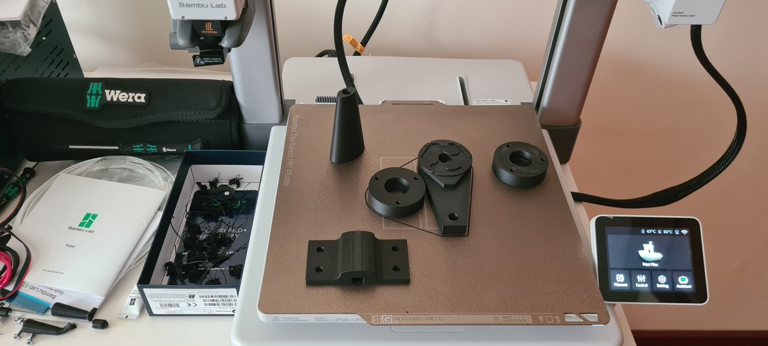
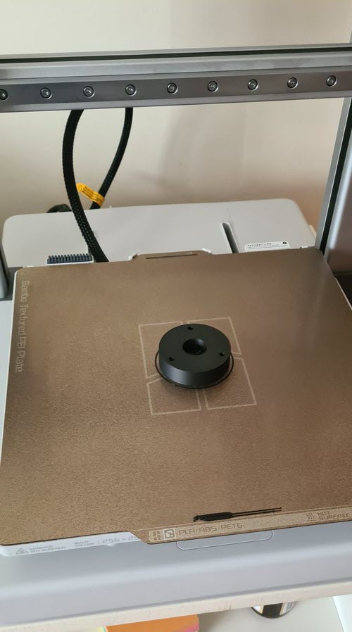
printed parts.
I printed most of the structural parts in black PLA on my Bambu Lab A1 at home. The Arduino UNO + CNC Shield enclosure was a separate job — I printed it on one of the A1 mini units at Fab Lab León in grey PLA, while I was still on site, so it made more sense to run it there than bring it home.
The gallery below also documents a small reprint loop: one of the circular brackets came out with surface defects on its first attempt, caused by the orientation of the part on the build plate. Flipping the support face in OrcaSlicer and reprinting fixed it cleanly.
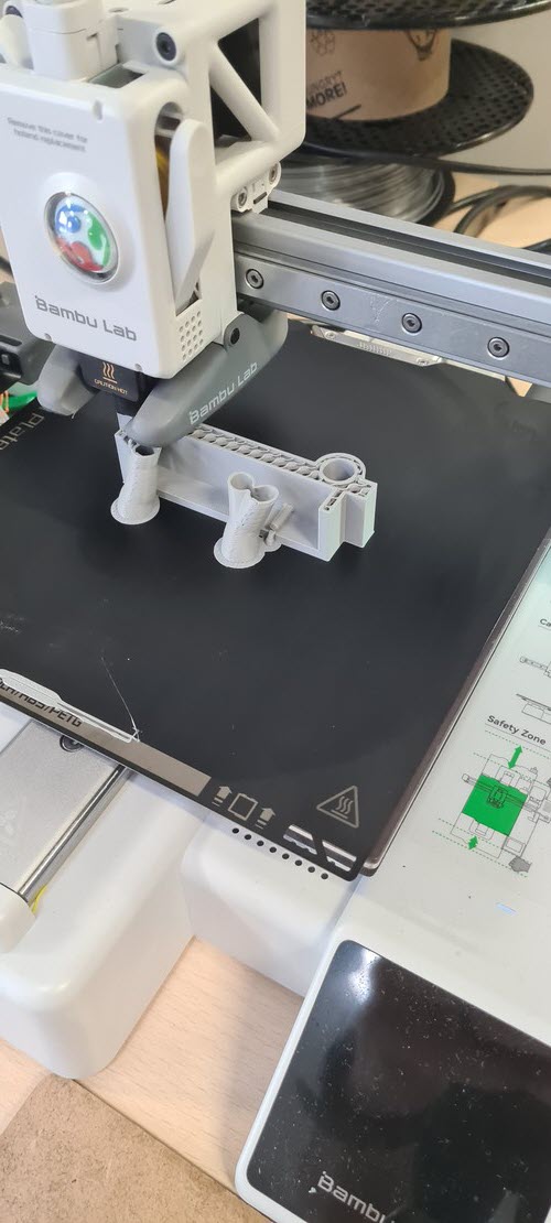
The Arduino UNO + CNC Shield enclosure design and Fusion 360 work is documented in the next section.
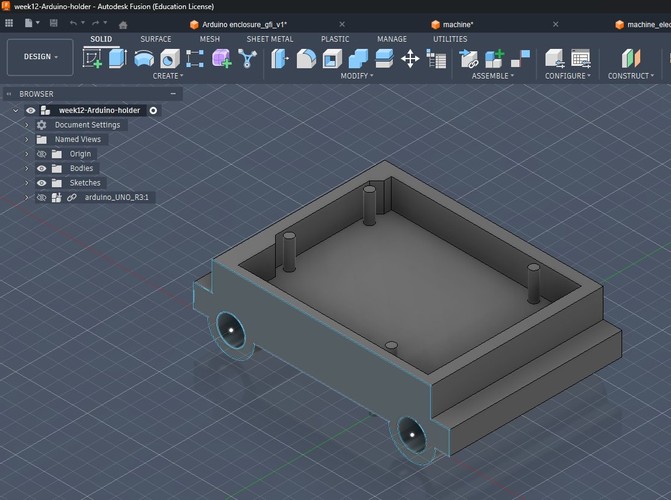
fusion 360 modelling — arduino + CNC shield enclosure.
We needed a clean way to mount the Arduino UNO + CNC Shield V3.0 on the lathe frame. Rather than designing an enclosure from scratch, I forked David Fernández’s 2025 enclosure (see links section) and adapted it to our mounting points and cable routing.
What I changed:
- Repositioned the mounting tabs to match the holes available on our lathe frame.
- Opened the cable-exit side to route the stepper wires and the USB cable cleanly.
- Tweaked the internal standoffs for the Arduino UNO R3 footprint (I dropped the Arduino UNO step file from GrabCAD into the browser tree just as a reference body, visible in the screenshot).
- Kept the overall form factor so the original lid — which I didn’t touch — still fits.
What I kept from David’s design:
- The general tray geometry and wall thickness (2.4 mm), which works well with PLA at 0.2 mm layer height.
- The corner reinforcements.
Credit where it’s due: the bulk of the design thinking was David’s. My work here was adaptation, not design from scratch.
electronics — arduino UNO + CNC shield v3.0 + DRV8825.
The electronics stack we settled on for the lathe is the classic GRBL-on-Arduino combo:
- Arduino UNO R3 running GRBL 1.1.
- CNC Shield V3.0 stacked on top.
- DRV8825 stepper drivers — one per axis (X, Y and Z). The shield has slots for four; we use three.
- NEMA 17 steppers: RB 17HDC1220-300N for X and Y, Stepperonline 17HE19-2004S (2 A, 55 N·cm) for Z.
- G-code sent from a laptop via Universal G-Code Sender (UGS).
Setup notes:
- DRV8825 current limit. The driver’s datasheet gives the relationship
I = Vref × 2with the common Rsense of 0.100 Ω. We used two different motors:- X and Y axes — RB 17HDC1220-300N. No official datasheet, so instead of sizing the current from a motor rating, we sized it from the driver’s safe upper limit: the DRV8825 can push up to 2.2 A but stays comfortable around ~1.84 A per phase with a heatsink. Target: Vref ≈ 0.92 V (since
1.84 / 2 = 0.92). Same approach Álvaro Macián documented in 2020. - Z axis — Stepperonline 17HE19-2004S, rated 2.0 A per phase. Theoretical target is Vref ≈ 1.0 V, but in practice we backed it off slightly to keep the driver within a safe thermal margin during continuous operation.
- X and Y axes — RB 17HDC1220-300N. No official datasheet, so instead of sizing the current from a motor rating, we sized it from the driver’s safe upper limit: the DRV8825 can push up to 2.2 A but stays comfortable around ~1.84 A per phase with a heatsink. Target: Vref ≈ 0.92 V (since
- Three microstep jumpers installed per driver slot → 1/32 microstepping. Overkill for the lathe’s force profile, but the quieter motion made testing much more pleasant.
- GRBL
$100/$101/$102(steps/mm for X, Y, Z) calibrated empirically with a caliper on a manual 50 mm jog.
Most of this is well-trodden ground; see the links section for the tutorials I followed. The bring-up itself was done jointly with Óscar Cela.
troubleshooting notes.
Two dead-ends from the electronics bring-up worth keeping around. Beni covers the whole sequence on the group page, so I only want to flag the bits that actually tripped us up.
Arduino Nano bootloader. First attempt was on an Arduino Nano. The Arduino IDE kept reporting “upload successful” and then the board just sat there, not responding on serial. Classic silent failure. Adrián dropped by, took one look at it and asked whether we had tried the old bootloader — turns out most of these cheap Nano clones ship with the old one but the IDE defaults to the new. Switch to Tools → Processor → ATmega328P (Old Bootloader), upload again, and done. If you ever see avrdude: stk500_recv(): programmer is not responding on a Nano clone, try this before anything else. We ended up moving to the UNO for other reasons (next point), but this is useful general-purpose knowledge.
The HW-702 shield that didn’t work. Our first shield was a HW-702 v0.0.0, sold as “CNC Shield V4”. With DRV8825 drivers on it, the motors were clearly alive — you could hear the coils being energised and the shafts locked in place with holding torque — but they just would not turn. No step response on any axis. We spent a good while on the current limit pots, reseating drivers, re-checking microstep jumpers, the usual things. Nothing.
The fix was to just switch to a plain CNC Shield V3.0, everything else the same. Motors moved on first try. To be sure the DRV8825s weren’t part of the problem, we then put the lab’s older A4988 drivers on the V3.0 shield — also fine. So the fault was specifically the HW-702 unit we had.
I’m not going to say the HW-702 is broken by design — ours may well have been a defective unit — but for the group’s sanity we froze the setup on the V3.0 shield and moved on. The one thing I’d keep from this: when two things change and something starts working, you don’t really know why yet. Change them back one at a time.
material for mechanical tests.
I picked up some soft white foam cylinders as first stock for the lathe. Logic: if the machine can’t turn foam cleanly, no point trying wood or plastic yet. Foam is also safe — nothing dramatic happens if something slips.
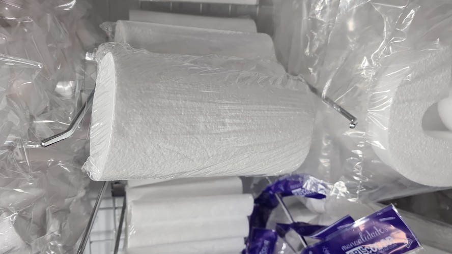
Once the kinematics hold up with foam we’ll move to soft wood (pine) and eventually machinable wax for the geometry-heavy tests.
reflections.
What worked. Forking David’s enclosure instead of designing one from scratch saved me at least a full day in Fusion 360, and gave us a mount that was already validated for PLA printing. The print-time study felt like busywork at first but ended up being the most useful planning artefact of the week — it forced us to agree on priorities before anyone kicked off a six-hour print.
What didn’t. The Z axis didn’t have enough force for what we were asking it to do. We first ran Z with a standard NEMA 17, and when the motor kept stalling under cutting load we swapped it for a larger, higher-torque NEMA 17 — same story, barely any improvement.
My initial reading of this was that a stepper was just the wrong motor type for a rotational axis. Neil corrected that framing during the global class — and he was right: the real trade-off is more nuanced than “stepper vs. everything else”. There are two independent axes of that trade-off:
- Sizing and reduction. A bare stepper loses torque fast at higher RPM, but a gearhead stepper (with an integrated planetary reducer, typical ratios 5:1 to 20:1) multiplies output torque by the reduction ratio at the cost of RPM. That alone could have solved our problem at the low-to-mid RPM range we actually need for cutting polystyrene.
- Open-loop vs. closed-loop. A stepper with an encoder and a closed-loop driver (e.g. Leadshine CL57) is functionally a servo — it detects and corrects lost steps in real time. From the outside, the distinction between “stepper with encoder” and “servo” becomes mostly about naming.
So our actual mistake wasn’t the motor category — it was running a bare, open-loop stepper sized only from holding torque, in an application where we needed torque at meaningful RPM under load. The 2015 italian team sidestepped all of this by using a hand drill (a geared DC motor) for this axis, which is another reasonable path.
Realistic upgrade paths for a second iteration, without ranking them:
- Gearhead stepper — same firmware (plain GRBL), smallest change to the existing stack.
- Closed-loop stepper — still compatible with GRBL at the step/dir level, adds robustness against lost steps.
- DC motor with a speed controller — matches the italian reference, cheap, smooth continuous rotation.
- BLDC motor with an ESC, or a BLDC servo with closed-loop driver — the industrial-style solution. Gets expensive, and plain GRBL doesn’t drive it natively; you’d need grblHAL or LinuxCNC.
The group page already leaves the door open to a DC motor for Z. After Neil’s comment I’d add the gearhead stepper option to that list — it’s the smallest jump, and on paper it directly addresses the torque-at-RPM problem we actually had.
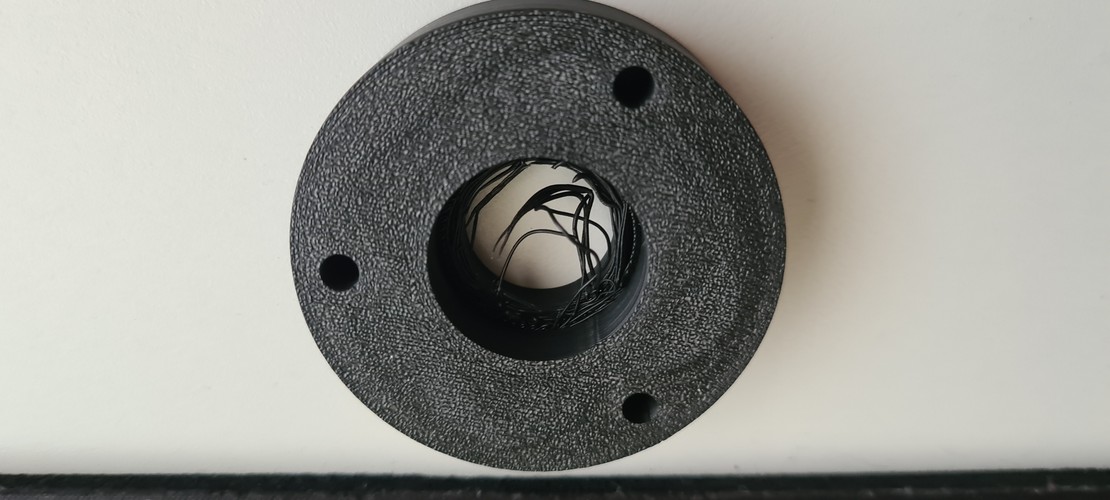
Minor aside: the stringing on some of the PLA circular brackets (visible in the close-up) is also ugly. Retraction/temperature issue on my A1 profile, not a design problem — parts are structurally fine for the lathe but I need a cleaner profile before the standing desk prints.
What I’d do differently. I underestimated how much of “machine design” is really about tolerances between 3D-printed parts and metal hardware (bearings, lead screws, rods). Next time: print the critical-interface parts first, check fits, then print the rest of the frame.
Connection to the final project. This week is a direct rehearsal for the standing desk: multi-node coordinated motion, 3D-printed structural parts, stepper drivers, a command protocol over a serial link. The lathe has three axes (X, Y, Z) driven independently; the desk has four legs that need to stay within ±2 mm of each other. Different scale of coordination problem, but same ingredients.
Next steps. Done — see the presentation video below.
presentation video.
Recording of the one-minute presentation of CYLINDRATOR during the global class with Neil on April 22, 2026. You can also see Beni and Óscar at Fab Lab León in the background.
Neil’s feedback during this exact moment is what drove the update to the reflections section above — specifically, the more nuanced framing about steppers, gearheads and closed-loop control.
files.
- Presentation video: week12_presentation_video_2026-04-22.mp4
- Fusion 360 source — forked Arduino enclosure: week12-Arduino-holder.f3z
- STL of the forked enclosure: week12-Arduino-holder.stl
links.
Group and reference designs
- Fab Lab León 2026 — group page: https://fabacademy.org/2026/labs/leon/mtm/index.html
- David Fernández — Fab Lab León 2025, Week 12 (primary reference for the enclosure fork): https://fabacademy.org/2025/labs/leon/students/david-fernandez/assignments/week12.html#files
- Adrián (local instructor) — Fab Lab León 2020 machine assignment: https://academany.fabcloud.io/fabacademy/2020/labs/leon/leon-group-assignments/machine/leonmachine2020.html
Italian 2015 reference group (main design inspiration for our lathe)
- Gianluca Pugliese — Exercise 16: https://fabacademy.org/archives/2015/eu/students/pugliese.gianluca/exercise16.html
- Enrico Bassi — Week 16 machine: https://fabacademy.org/archives/2015/eu/students/bassi.enrico/16machine.html
- Daniele Ingrassia — index: https://fabacademy.org/archives/2015/eu/students/ingrassia.daniele/index.html
MIT MTM (conceptual root)
- MIT CBA MTM, 2014 edition: https://mtm.cba.mit.edu/2014/2014_mmtm/index.html
Fab Academy class material
- Machine Design 2026 class page: https://fabacademy.org/2026/classes/machine_design/index.html
Electronics — GRBL + CNC Shield + DRV8825
- DIY Engineers — GRBL with Arduino CNC Shield, complete guide: https://www.diyengineers.com/2023/01/05/grbl-with-arduino-cnc-shield-complete-guide/
- HowToMechatronics — GRBL control CNC machine with Arduino: https://howtomechatronics.com/tutorials/how-to-setup-grbl-control-cnc-machine-with-arduino/
- Alhekmh — HW-702 v0.0.0 CNC Shield V4 notes: https://alhekmh.com/hw-702_v0-0-0-cnc-shield-v4/
- 38-3D — Cómo usar el Arduino CNC Shield V3.0 (ES): https://es.38-3d.co.uk/blogs/blog-38-3d/como-usar-el-arduino-cnc-shield-v3-0
- Universal G-Code Sender (UGS) releases: https://github.com/winder/Universal-G-Code-Sender/releases