Networking and communications
weekly schedule.
| Time block | Wed | Thu | Fri | Sat | Sun | Mon | Tue | Wed |
|---|---|---|---|---|---|---|---|---|
| Global class | 3 h | |||||||
| Local class | 1,5 h | 1,5 h | ||||||
| Research | 1 h | 2 h | ||||||
| Design | ||||||||
| Fabrication | ||||||||
| Documentation | 3 h | |||||||
| Review |
overview.
Week 11 covers the full communication stack: from chip-to-chip protocols like I2C, SPI, and UART, through device-to-device networking over Wi-Fi and Bluetooth, to long-range systems like LoRa. The practical focus in Fab Academy sits between OSI Layer 1 (the physical board) and Layer 3 (the local network). The session was taught by Eric Pan, Henk Buursen, Luc Hanneuse, and Saheen Palayi.
This week connects directly to my final project: the height-adjustable standing desk uses a UART bus with software addressing — one XIAO ESP32-S3 as master and one XIAO RP2040 per leg as slave. Understanding addressing, poll cycles, and message framing is not academic for me — it is a prerequisite for the actual build.
learning objectives.
- Demonstrate workflows used in network design.
- Implement and interpret networking protocols and/or communication protocols.
- Understand how software node addresses replicate the role of hardware bus addresses (I2C, CAN).
assignments.
- Group assignment: Send a message between two projects. Documented here and on the Fab Lab León 2026 Group Page.
- Individual assignment: Design, build, and connect a wired or wireless node with a network or bus address and a local input and/or output device.
research.
protocol overview.
The class structured communication into three layers of increasing scope:
Chip-to-chip (synchronous):
- I2C — two wires (SDA + SCL), multi-device bus, each peripheral has a 7-bit address. Needs pull-up resistors. Best for sensors and OLEDs when wire count matters more than speed.
- SPI — four wires (SCK, PICO, POCI, CS), one CS pin per device, up to 10 MHz+. Full-duplex. Best for SD cards, displays, or anything that needs high throughput.
Device-to-device (asynchronous):
- UART — two wires (TX, RX), no clock line, baud rate agreed in advance. The simplest protocol. Indispensable for debugging.
- RS-485 — differential signaling, high noise immunity, up to ~1.2 km. The industrial workhorse. My final project originally considered this before settling on CAN.
- CAN bus — differential, multi-master capable, hardware arbitration, 11-bit or 29-bit addresses. Designed for electrically noisy environments (automotive). The target protocol for my standing desk.
Wireless:
- BLE — 2.4 GHz, ~10–100 m, ultra-low power. GATT profile with services and characteristics. Native support on XIAO ESP32-S3.
- Wi-Fi — high throughput, gateway to the internet. The ESP32-S3 handles both BLE and Wi-Fi on the same chip.
- LoRa — sub-GHz (868 MHz in Europe), 2–15 km, years on a single battery. Luc Hanneuse mentioned up to 10,000 devices on a single LoRaWAN gateway. Óscar from Ayto Ponferrada had a 200 km link with a special antenna — that blew my mind.
protocol selection for the final project.
Before committing to a bus protocol, I researched what the standing desk industry actually uses. The answer was consistent across manufacturers: LIN bus (IKEA Bekant, LINAK actuators) or plain UART (Autonomous, the manufacturer of my reference desk). Both are single-master, polled architectures. Neither uses CAN. The RJ45 connectors visible in commercial desks are just a convenient multi-conductor housing — the protocol inside is UART or LIN at 9600–19200 baud, not Ethernet.
This matters because CAN was my initial assumption, inherited from the automotive framing of the problem. Re-examining it: a standing desk has one master, four slaves, low data rate (~10 bytes per poll), short distances (~2 m), no simultaneous transmission from multiple nodes, and no hard fault-tolerance requirement. CAN’s hardware arbitration and differential signaling solve problems this project does not have.
The table below compares the four realistic options for the final project bus:
| Criterion | UART point-to-point | UART + software addressing | LIN bus | CAN bus |
|---|---|---|---|---|
| Wires between nodes | 2 per leg (4 pairs total) | 2 shared + GND | 1 + GND | 2 differential + GND |
| Extra hardware per node | None | None | TJA1020 transceiver (~0.50 €) | MCP2515 + SN65HVD230 (~5 €) |
| XIAO RP2040 native support | Yes (UART) | Yes (UART) | Yes (UART + framing) | No (SPI adapter needed) |
| PCB complexity | Low | Low | Low | High |
| Addressing | Implicit (pin = leg) | Software, 1 byte in frame | Hardware (LIN ID field) | Hardware (11-bit CAN ID) |
| Multi-master | No | No | No | Yes (not needed) |
| Industry precedent for desks | No | Yes (Autonomous) | Yes (IKEA, LINAK) | No |
| Synchronization risk | High (no coordination) | Manageable (polled) | Manageable (polled) | Low |
| Fab Academy Week 11 scope | Simple | Simple | Medium | Complex |
Decision: UART with software addressing (Option B). It matches the industry approach, requires zero additional hardware beyond the XIAO RP2040 boards already designed, keeps PCB fabrication simple, and validates directly in Week 11.
What “software addressing” means. Standard UART is point-to-point — one transmitter, one receiver, no concept of addresses. Hardware protocols like I2C or CAN solve multi-device communication at the silicon level: the peripheral itself filters incoming frames and only interrupts the CPU when the address matches. UART has no such mechanism. Software addressing means building that filtering in firmware. Every frame starts with a DEST_NID byte. Every node receives every frame on the shared bus, but the firmware immediately checks whether DEST_NID matches its own node ID — if not, it discards the frame and returns to listening. The check happens in code, not in hardware. From the application layer the result is identical to I2C addressing; it just lives one layer up.
The analogy with I2C is intentional but has limits — and explains why I2C and SPI were discarded for this bus.
I2C requires pull-up resistors on both SDA and SCL, and more importantly it is a synchronous protocol: it needs a shared clock line (SCL) in addition to the data line. That means three wires between nodes instead of two. For a desk where the bus runs through moving telescopic columns, every additional wire is a potential failure point.
SPI was discarded even faster. SPI is point-to-point by design: to address N devices you need N separate chip-select (CS) lines from the master. Four leg nodes would require four CS pins on the ESP32-S3 master and four dedicated wires — a star topology that fights the physical layout of a desk. SPI is the right choice for high-speed peripherals on the same PCB; it does not scale to a multi-node bus over metre-long cables.
UART needs only two wires (TX + RX, with shared GND). No clock line, no chip-select, no pull-up requirements. The software address layer adds the multi-node capability that UART lacks natively, at zero hardware cost.
architecture: master–slave over UART. The structure remains master–slave. The XIAO ESP32-S3 is the single master; each XIAO RP2040 leg board is a slave with a fixed node ID (NID 1–4). The master polls each slave in sequence: it sends a request frame addressed to one leg, waits for the response (distance reading + motor status), then moves to the next. No slave transmits unsolicited.
Centralisation of information. All state lives on the master. The ESP32-S3 holds the current height of each leg (from the VL53L0X readings), the target height, and the synchronisation logic. The touchscreen display connects directly to the master via I2C or SPI — it never touches the UART bus. The display shows current height, preset buttons, and any leg that is out of sync.
Synchronisation between legs. This is the main risk. Four legs driven independently will drift apart if each runs open-loop (step count only). The mitigation is closed-loop position control per leg using the VL53L0X ToF sensor: the master reads each leg’s distance every poll cycle and adjusts the motor command (speed or enable/disable) to keep all four within a tolerance band (e.g., ±2 mm). This is the same approach used in commercial desks — the anti-collision and levelling logic runs in the control box, not in the motors.
Specific risks and mitigations:
| Risk | Cause | Mitigation |
|---|---|---|
| Legs drift apart during movement | Open-loop stepper control | Closed-loop: master reads VL53L0X per leg each cycle, halts fast legs |
| One leg stalls (obstacle, mechanical binding) | Motor stops but others continue | Master detects no encoder/ToF change → emergency stop all legs |
| UART frame lost (noise) | Electrical interference from motor drivers | Checksum per frame; master retries once before stopping |
| Poll latency too high at 4 legs | 4 × round-trip at 9600 baud | Use 115200 baud; at 6-byte frames, 4-leg cycle < 5 ms |
At 115200 baud, the bus transmits 115200 bits per second. With 10 bits per byte (1 start bit + 8 data bits + 1 stop bit), that is 11,520 bytes per second, or roughly 0.087 ms per byte.
One full exchange for a single leg is 12 bytes — 6 for the master’s request frame and 6 for the slave’s response:
12 bytes × 0.087 ms/byte ≈ 1.04 ms per leg
Four legs polled in sequence:
4 × 1.04 ms ≈ 4.2 ms per full cycle
During those 4.2 ms the desk moves at 31.75 mm/s. The maximum distance one leg can travel between two consecutive corrections is:
31.75 mm/s × 0.0042 s ≈ 0.133 mm
That is the worst-case inter-leg drift: one leg has just been corrected, the next one waits a full cycle before being read. In practice the drift is smaller because the master corrects each leg on every poll, not only at the end of the cycle.
With a ±2 mm inter-leg tolerance (a conservative threshold to avoid mechanical stress on the tabletop), the safety margin is ×15. The protocol has ample headroom even accounting for processing overhead or occasional checksum retransmissions.
group assignment.
The group assignment required sending a message between two projects. Fab Lab León 2026 Group Page.
I chose Bluetooth Low Energy (BLE): it demonstrates a complete wireless node with addressing (GATT service and characteristic UUIDs define the address space), uses hardware already on hand (XIAO ESP32-S3), and the second “project” is a smartphone running nRF Connect — which the FAQ explicitly allows as a valid node.
setup.
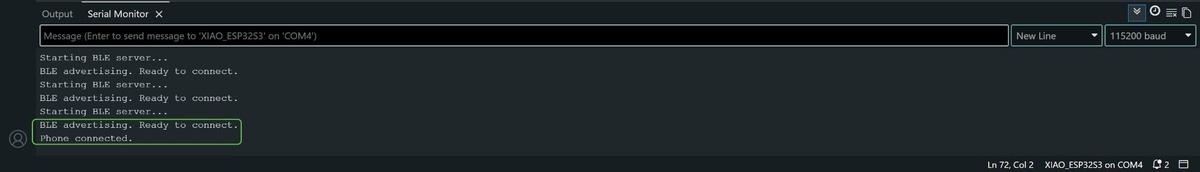
The XIAO ESP32-S3 runs as a BLE server. It advertises a GATT service with a single readable characteristic holding a text string. The smartphone connects as a GATT client and reads the characteristic value.
Hardware: Seeed Studio XIAO ESP32-S3
IDE: Arduino IDE 2.x with the Espressif esp32 board package
App: nRF Connect (Nordic Semiconductor)
Library: BLEDevice, BLEServer, BLEUtils — included in the Espressif Arduino core, no separate installation needed
server code.
tab: BLE server — XIAO ESP32-S3 | ble-server-esp32s3.ino
#include <BLEDevice.h>
#include <BLEUtils.h>
#include <BLEServer.h>

// UUIDs generated at https://www.uuidgenerator.net/
#define SERVICE_UUID        "4fafc201-1fb5-459e-8fcc-c5c9c331914b"
#define CHARACTERISTIC_UUID "beb5483e-36e1-4688-b7f5-ea07361b26a8"

void setup() {
  Serial.begin(115200);
  Serial.println("Starting BLE server...");

  BLEDevice::init("XIAO_ESP32S3_FAB");
  BLEServer *pServer = BLEDevice::createServer();
  BLEService *pService = pServer->createService(SERVICE_UUID);

  BLECharacteristic *pCharacteristic = pService->createCharacteristic(
    CHARACTERISTIC_UUID,
    BLECharacteristic::PROPERTY_READ | BLECharacteristic::PROPERTY_WRITE
  );

  pCharacteristic->setValue("Hello from Fab Lab Leon!");
  pService->start();

  BLEAdvertising *pAdvertising = BLEDevice::getAdvertising();
  pAdvertising->addServiceUUID(SERVICE_UUID);
  pAdvertising->setScanResponse(true);
  pAdvertising->setMinPreferred(0x06);
  pAdvertising->setMaxPreferred(0x12);
  BLEDevice::startAdvertising();

  Serial.println("BLE advertising. Connect with nRF Connect and read the characteristic.");
}

void loop() {
  delay(2000);
}
tab: end
procedure.
- Flash the sketch to the XIAO ESP32-S3. Open the Serial Monitor at 115200 baud and confirm the “BLE advertising” message.
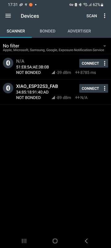
- On the smartphone, open nRF Connect → Scanner tab → Start scan.
- Locate
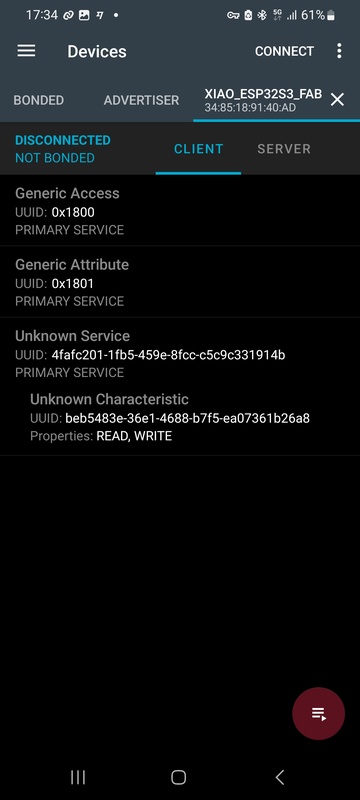
XIAO_ESP32S3_FABin the device list and tap Connect. - Expand the service with UUID
4fafc201-.... - Tap the read icon (down arrow ↓) on the characteristic
beb5483e-.... - The app displays the value in hex and decoded ASCII.
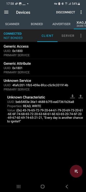
what I learned.
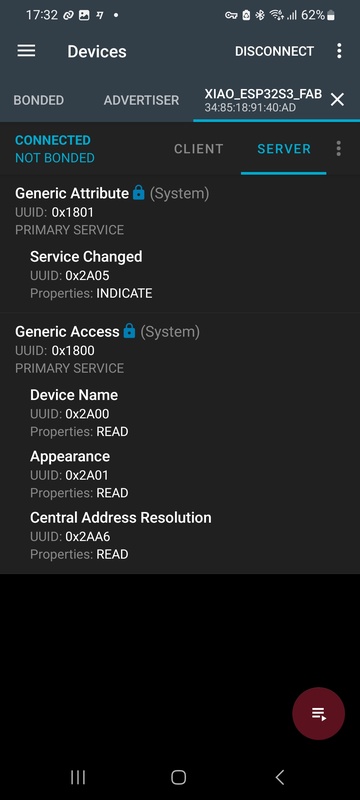
BLE addressing works at two levels: the MAC address of the device (handled automatically by the stack) and the GATT hierarchy of service UUID → characteristic UUID. The UUID is how the client selects exactly which data to read. When the assignment says “network or bus address,” in BLE this maps to the characteristic UUID.
The setMinPreferred(0x06) and setMaxPreferred(0x12) calls address a known compatibility issue with iPhone BLE connections. Without them, iOS sometimes fails to complete GATT discovery.
individual assignment.
plan and hardware.
The individual assignment requires a node with a network or bus address and a local input or output device. I am reusing boards I already had — the FAQ explicitly permits commercial boards, including Arduino. The master is a board of my own design and fabrication (designed in Week 06, milled in Week 08), which satisfies the commercial board policy: the Arduino UNO R3 and the XIAO ESP32-S3 are allowed as the other two nodes because at least one board on the bus is mine.
Three nodes share a single UART bus. Two nodes is enough to demonstrate request/response addressing, but not enough to prove the bus is truly shared — with two nodes it could just be point-to-point UART with address labels painted on. Three nodes make it unambiguous: each node must actively ignore frames addressed to the other two.
Nodes:
- Node 0 — Master (NID 0): XIAO RP2040 on my own milled board (Week 06 design, Week 08 fabrication). Drives the timing loop and sends LED commands to both slaves.
- Node 1 — Slave A (NID 1): Arduino UNO R3 (ATmega328P, 5 V). Listens on the bus with
SoftwareSerial, keeping its hardware UART (D0/D1) free for the USB monitor. Local output: red LED. - Node 2 — Slave B (NID 2): XIAO ESP32-S3 (from the group assignment). Local output: green LED.
Protocol: UART, 9600 baud
Addressing: 1-byte node ID (NID) in each frame header
I dropped the bus to 9600 baud for two reasons tied to the Arduino node: SoftwareSerial on the UNO is not reliable much above ~38400, and at 9600 the wide bit timing makes the 3.3 V (XIAO) → 5 V (Arduino) level difference a non-issue on the receive line. Six-byte frames every 2 s leave the bus almost idle, so the lower rate costs nothing here.
Demo — distributed traffic light. The master runs a fixed 2-second cycle. On the first half it sends a LED-ON frame to node 1 (red) and a LED-OFF frame to node 2 (green). On the second half it reverses: LED-OFF to node 1, LED-ON to node 2. The two LEDs are never on at the same time.
Both command frames travel on the same shared physical bus. Node 1 executes only the frame whose DEST_NID is 1 and ignores the one addressed to NID 2. Node 2 does the opposite. The Serial Monitor on the master prints the DEST_NID of every frame sent, making the selective addressing explicitly visible in software.
The demo requires no sensor — the timing logic lives entirely on the master. This keeps the hardware setup minimal and the bus behaviour easy to photograph and explain.
I chose UART because it is the simplest possible foundation for testing a request/response addressing scheme with software addressing — the same architecture the final project uses.
addressing scheme.
Every board has a fixed Node ID (NID) defined in firmware. I use decimal numbering and the NID label on purpose. This is an application-layer identifier that travels inside the UART frame and is filtered in software — it is not an I2C device address. I2C addresses are 7-bit hardware addresses written in hex by convention (the VL53L0X answers at 0x29), and the silicon itself does the filtering. Writing my UART node addresses in hex made reviewers read them as I2C addresses, so I switched the whole bus to decimal NIDs to keep the two concepts visually separate.
NID 0 — Master  (XIAO RP2040, my own milled board)
NID 1 — Slave A (Arduino UNO R3)        → red LED
NID 2 — Slave B (XIAO ESP32-S3)         → green LED
Each board declares its own identity as a named constant, so the addressing is explicit and self-documenting in every sketch:
#define NID_MASTER  0
#define NID_RED     1   // slave A, red LED
#define NID_GREEN   2   // slave B, green LED
Frame format (6 bytes):
Byte 0: START     — 0xFF (frame delimiter, never a valid NID)
Byte 1: DEST_NID  — destination node ID
Byte 2: SRC_NID   — source node ID
Byte 3: CMD       — command code
Byte 4: PAYLOAD   — data byte (0 if unused)
Byte 5: CHECKSUM  — XOR of bytes 1–4
The START byte stays in hex (0xFF) because it is a delimiter byte pattern, not an address — it is chosen precisely so it can never collide with a NID value.
Commands:
CMD 0x03 — LED command (payload: 0 = off, 1 = on)Every node reads every frame on the shared bus, but acts only when DEST_NID matches its own NID; otherwise it discards the frame and keeps listening — see the software addressing explanation in the research section above.
wiring.
In this demo the master only transmits and the two slaves only listen, so the bus is a single shared line: the master’s TX fans out to the RX of both slaves, with a common GND. No slave ever drives the line. This deliberately sidesteps the bus-contention problem of multi-drop UART — when two transmitters share one wire, the idle one must go to high impedance or both push-pull outputs fight each other. Here that never happens because the slaves do not transmit; if the final project needs slave responses, that is where half-duplex with a tri-stated TX comes in.
Node 0 — Master          Node 1 — Slave A         Node 2 — Slave B
XIAO RP2040              Arduino UNO R3            XIAO ESP32-S3
(my own milled board)    (5 V)                    (3.3 V)

GPIO0 / TX1  ───┬────────  D8 (SoftwareSerial RX)
                └────────  GPIO44 / RX  (ESP32-S3)

GND          ────────────  GND           ─────────  GND
The single shared line carries the master TX (3.3 V) to both slave RX pins. Driving the Arduino’s 5 V input from a 3.3 V output is safe in this direction, and the only place the levels meet is that RX pin — the master never receives, so the 5 V side never drives back into the 3.3 V XIAO. The Arduino listens on D8 via SoftwareSerial so its hardware UART (D0/D1) stays free for the USB monitor. The XIAO ESP32-S3 uses Serial1 mapped to GPIO43 (TX) / GPIO44 (RX) in the Espressif Arduino core; here only its RX (GPIO44) is wired. All three grounds are tied together — essential, since each board is powered from its own USB.
Red LED on slave A (NID 1): 220 Ω resistor to D7 on the Arduino. Green LED on slave B (NID 2): 220 Ω resistor to GPIO2 on the ESP32-S3.
I drew the bus topology in Excalidraw before wiring it on the bench:
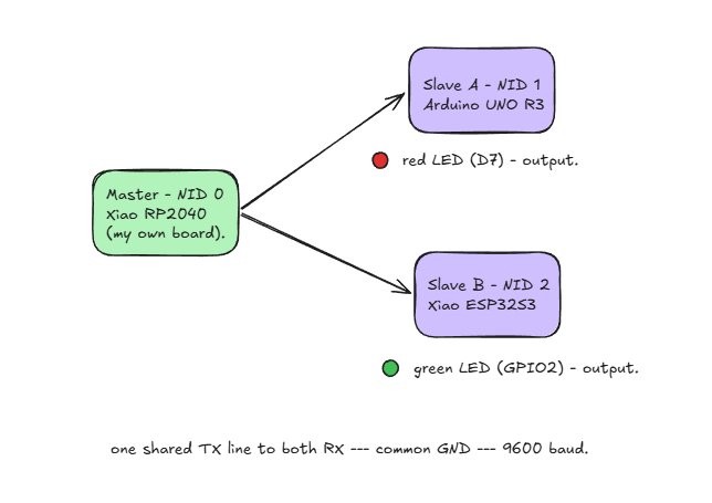
The hero shot at the top of this page is this exact bench, so it doubles as the wiring photo: the master TX line branches to both slave RX pins, the two LEDs sit on the breadboard, and all three grounds share the rail.
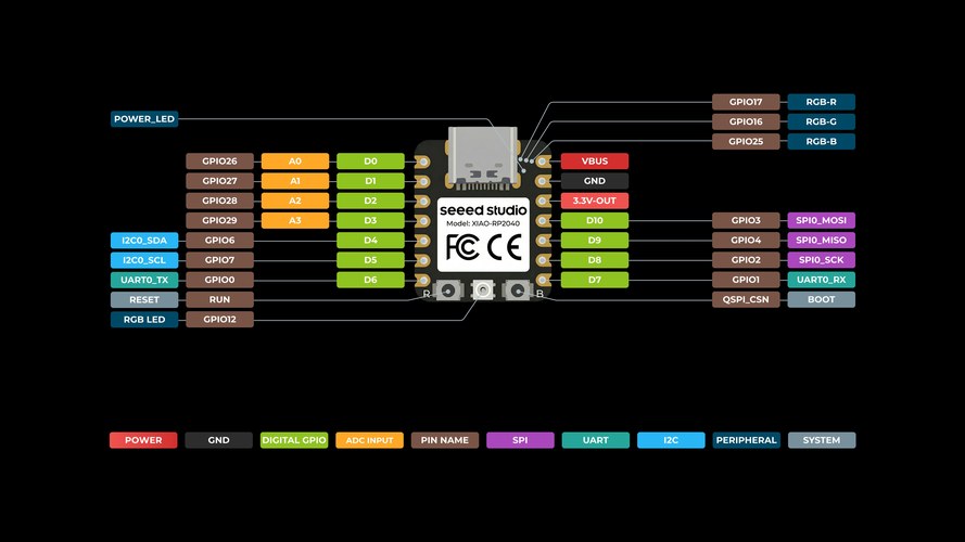
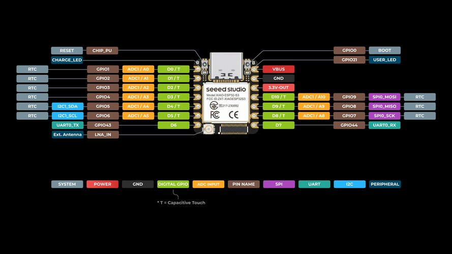
pinouts.
Every pin in the wiring above comes straight from these pinouts. On the master, D6 is GPIO0 = UART0 TX; on the ESP32-S3, D7 is GPIO44 = UART0 RX and the green LED sits on GPIO2 (D1). The Arduino UNO R3 pins (D8 for SoftwareSerial RX, D7 for the red LED) are on its own pinout, linked below for download.
The Arduino UNO R3 (red slave) pinout is the official Arduino sheet: A000066-full-pinout.pdf.
code.
The three sketches share the same 6-byte frame and the same NID constants. The master only writes; each slave reads every frame and acts only on the one whose DEST_NID is its own.
tab: Master — NID 0 | uart-master.ino
// uart-master.ino — Node 0 (master), XIAO RP2040 on my own milled board
// The master only transmits. Fixed 2 s traffic-light cycle, 6-byte frames.

#define NID_MASTER  0
#define NID_RED     1   // slave A, red LED
#define NID_GREEN   2   // slave B, green LED

#define FRAME_START 0xFF
#define CMD_LED     0x03

const unsigned long PHASE_MS = 2000;
unsigned long lastSwitch = 0;
bool phaseA = true;

void sendFrame(uint8_t dest, uint8_t cmd, uint8_t payload) {
  uint8_t checksum = dest ^ NID_MASTER ^ cmd ^ payload;
  Serial1.write(FRAME_START);
  Serial1.write(dest);
  Serial1.write((uint8_t)NID_MASTER);
  Serial1.write(cmd);
  Serial1.write(payload);
  Serial1.write(checksum);

  Serial.print("TX  DEST_NID=");
  Serial.print(dest);
  Serial.print("  CMD=0x");
  Serial.print(cmd, HEX);
  Serial.print("  PAYLOAD=");
  Serial.println(payload);
}

void setup() {
  Serial.begin(9600);    // USB, monitor
  Serial1.begin(9600);   // UART bus, TX = GP0 (D6)
  unsigned long t0 = millis();
  while (!Serial && millis() - t0 < 3000) {}
  Serial.println("Master (NID 0) ready.");
}

void loop() {
  unsigned long now = millis();
  if (now - lastSwitch >= PHASE_MS) {
    lastSwitch = now;
    if (phaseA) {
      Serial.println("-- phase A: RED on, GREEN off --");
      sendFrame(NID_RED,   CMD_LED, 1);
      sendFrame(NID_GREEN, CMD_LED, 0);
    } else {
      Serial.println("-- phase B: RED off, GREEN on --");
      sendFrame(NID_RED,   CMD_LED, 0);
      sendFrame(NID_GREEN, CMD_LED, 1);
    }
    phaseA = !phaseA;
  }
}
tab: Slave A — red, NID 1 | uart-slave-red.ino
// uart-slave-red.ino — Node 1 (slave A), Arduino UNO R3
// Receive-only node on the shared bus at 9600 baud. SoftwareSerial on D8
// keeps the hardware UART (D0/D1) free for the USB monitor.

#include <SoftwareSerial.h>

#define MY_NID      1
#define NID_MASTER  0

#define FRAME_START 0xFF
#define CMD_LED     0x03

#define RX_PIN      8     // bus RX (master TX -> here)
#define TX_PIN      9     // unused, required by SoftwareSerial
#define LED_PIN     7     // red LED via 220 ohm to GND

SoftwareSerial busSerial(RX_PIN, TX_PIN);

uint8_t buf[6];
uint8_t idx = 0;

void handleFrame() {
  uint8_t dest = buf[1], src = buf[2], cmd = buf[3], payload = buf[4], chk = buf[5];
  if ((uint8_t)(dest ^ src ^ cmd ^ payload) != chk) {
    Serial.println(F("RX  bad checksum, frame dropped"));
    return;
  }
  if (dest != MY_NID) {
    Serial.print(F("RX  frame for NID "));
    Serial.print(dest);
    Serial.println(F(" - not me, ignored"));
    return;
  }
  if (cmd == CMD_LED) {
    digitalWrite(LED_PIN, payload ? HIGH : LOW);
    Serial.print(F("RX  DEST_NID=1 (me)  LED="));
    Serial.println(payload ? "ON" : "OFF");
  }
}

void setup() {
  Serial.begin(9600);       // USB monitor
  busSerial.begin(9600);    // UART bus on D8
  pinMode(LED_PIN, OUTPUT);
  digitalWrite(LED_PIN, LOW);
  Serial.println(F("Slave A (NID 1, red LED) ready - Arduino UNO."));
}

void loop() {
  while (busSerial.available()) {
    uint8_t b = busSerial.read();
    if (idx == 0 && b != FRAME_START) continue;   // resync on START
    buf[idx++] = b;
    if (idx == 6) { idx = 0; handleFrame(); }
  }
}
tab: Slave B — green, NID 2 | uart-slave-green.ino
// uart-slave-green.ino — Node 2 (slave B), XIAO ESP32-S3
// Same logic as slave A, NID 2, green LED. Serial1 remapped: RX 44, TX 43.

#define MY_NID      2
#define NID_MASTER  0

#define FRAME_START 0xFF
#define CMD_LED     0x03
#define LED_PIN     2     // GPIO2 (D1), green LED via 220 ohm
#define UART_RX     44    // GPIO44 (D7)
#define UART_TX     43    // GPIO43 (D6)

uint8_t buf[6];
uint8_t idx = 0;

void handleFrame() {
  uint8_t dest = buf[1], src = buf[2], cmd = buf[3], payload = buf[4], chk = buf[5];
  if ((uint8_t)(dest ^ src ^ cmd ^ payload) != chk) {
    Serial.println("RX  bad checksum, frame dropped");
    return;
  }
  if (dest != MY_NID) {
    Serial.print("RX  frame for NID ");
    Serial.print(dest);
    Serial.println(" - not me, ignored");
    return;
  }
  if (cmd == CMD_LED) {
    digitalWrite(LED_PIN, payload ? HIGH : LOW);
    Serial.print("RX  DEST_NID=2 (me)  LED=");
    Serial.println(payload ? "ON" : "OFF");
  }
}

void setup() {
  Serial.begin(9600);
  Serial1.begin(9600, SERIAL_8N1, UART_RX, UART_TX);
  pinMode(LED_PIN, OUTPUT);
  digitalWrite(LED_PIN, LOW);
  Serial.println("Slave B (NID 2, green LED) ready.");
}

void loop() {
  while (Serial1.available()) {
    uint8_t b = Serial1.read();
    if (idx == 0 && b != FRAME_START) continue;   // resync on START
    buf[idx++] = b;
    if (idx == 6) { idx = 0; handleFrame(); }
  }
}
tab: end
testing.
The video below is the whole bus running. I had three Serial Monitors open at 9600 baud — master, Arduino slave (NID 1) and ESP32-S3 slave (NID 2) — next to the two LEDs. Every two seconds the master sends one frame to each node and the LEDs swap red ↔ green, like a small traffic light.
Before the video, here is a still of the full setup — the three boards that make up the network, easier to zoom into than a video frame:
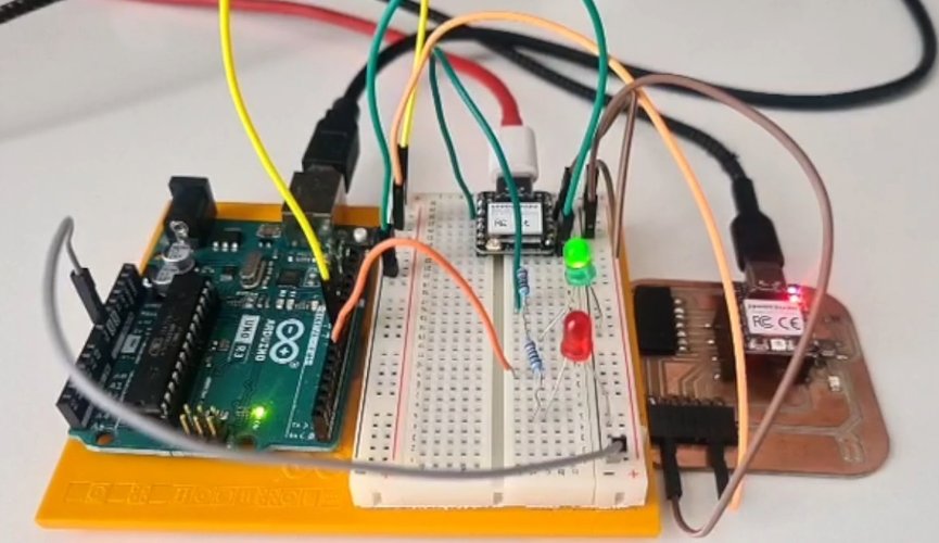
The addressing shows up clearly in the logs. Each slave prints RX frame for NID x - not me, ignored for the frames that aren’t for it, and RX DEST_NID=… (me) LED=ON/OFF for the ones that are. Both boards receive every byte on the shared line, but only the addressed node acts on it — which is the software addressing doing its job.
problems and solutions.
The QPAD wasn’t mine to modify. My first plan for slave A was the QPAD, but it belongs to the Fab Lab and I have to give it back, so soldering wires onto it was out. On top of that, its XIAO is soldered down with its pins tied to the touch pads, so there was no clean way to reach it from a breadboard either. I swapped slave A for an Arduino UNO R3 I already had. The FAQ only asks for one board of my own design and fabrication, and the master is my milled board, so two commercial boards next to it are fine.
115200 baud was too fast for the Arduino. I started the bus at 115200 like the BLE side, but the UNO has to listen with SoftwareSerial (its hardware UART is taken by USB), and SoftwareSerial gets unreliable above ~38400. I dropped the whole bus to 9600. Nice side effect: at 9600 the bit timing is relaxed enough that the 3.3 V (XIAO) vs 5 V (Arduino) difference on the RX line stops mattering. For six-byte frames every two seconds, 9600 is still basically an idle bus.
conclusions.
This week was more fun than I expected. Going from “two pins and a shared wire” to three boards that each know their own address and all talk on the same line made networking finally click for me in a way the theory never did. The software-addressing idea — every node hears everything, but only the one that is addressed acts on it — is simple and kind of beautiful.
It also matters for where my final project is heading. The standing desk already needs a small UART bus between the master and each leg, so this assignment was basically a rehearsal for that. In a future spiral I want to push it further: real slave responses (half-duplex with a tri-stated TX), a proper polling loop, and error handling beyond a single XOR checksum.
And this is where the rabbit holes start. LoRa alone — sub-GHz, kilometres of range, that 200 km link Óscar mentioned that blew my mind — is a whole world I want to dig into, and that is before getting anywhere near mesh networking, CAN or LIN. Communications turned out to be one of the topics I am most curious to keep exploring.
files and resources.
| File | Description |
|---|---|
| ble-server-esp32s3.ino | BLE server sketch for XIAO ESP32-S3 (group assignment) |
| uart-master.ino | Master sketch — traffic-light timing loop, sends LED frames to NID 1 and NID 2 |
| uart-slave-red.ino | Slave A sketch (NID 1, Arduino UNO R3) — SoftwareSerial on D8, filters by DEST_NID, drives red LED |
| uart-slave-green.ino | Slave B sketch (NID 2) — filters by DEST_NID, drives green LED |
| Master board design files (Week 06 / Week 08) | KiCad schematic, PCB and milling files for the self-fabricated master board |
| A000066-full-pinout.pdf | Official Arduino UNO R3 pinout sheet (red slave) |
References:
- Fab Academy 2026 — Networking and Communications
- Seeed Studio XIAO ESP32-S3 — Getting Started
- Seeed Studio XIAO RP2040 — Getting Started
- Arduino UNO R3 documentation (pinout source)
- Arduino SoftwareSerial library
- nRF Connect for Android
- Adrián Torres — Serial Bus example (Fab Academy 2020)
- Adrián Torres — I2C example (Fab Academy 2020)
- Fab Lab León 2026 Group Page