Week 10
Ouput devices
Contents
Starting Point
We are now taking one step further by adding output devices to our PCB. While last week focused on understanding how to read information from the environment, this week the focus shifts to how to respond to it.
We are surrounded by output devices all the time—LEDs, screens, speakers, and motors—but we rarely stop to think about how a simple signal from a microcontroller can be transformed into movement, light, or sound.
For someone like me, without a background in electronics, understanding how to control these devices and make them behave as expected is a significant challenge.
This week is about learning how to turn code into physical actions, connecting the digital world with real interaction.
Group assignment
We have decided that, as a group effort, each of us will specifically document some of the tests performed on our page.
Measure the power consumption of an output device
Power consumption of a DC Motor
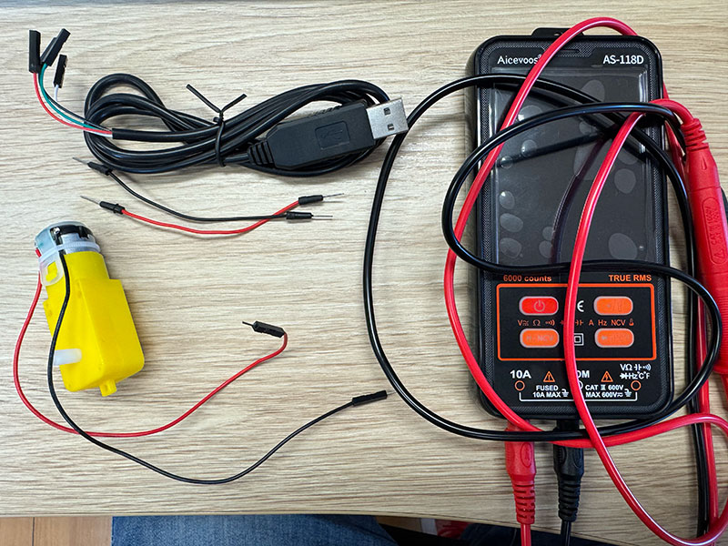
For the first task of the group assignment, the goal was to measure the power consumption of an output device. In our case, we decided to work with a DC motor taken from an Arduino robotics kit.
This motor includes a gear reduction box, which gives it low speed and high torque. Because of this, it is commonly used to drive wheels in small robot cars. According to its specifications, the motor can operate in a voltage range from 3V to 6V, so a 5V supply is suitable for testing it.
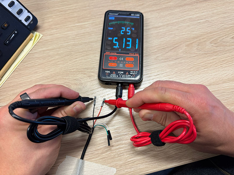
Before measuring the current consumption, the first step was to verify the output voltage of the power source. We used a USB cable as the supply and checked it with the multimeter in voltage mode. The measured value was 5.123V, confirming that the source was providing the expected 5V.
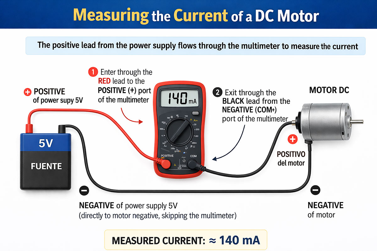
Once the supply voltage was confirmed, we moved on to measuring the current. To do this, it is important to remember that current must be measured in series, which means that the multimeter has to be inserted directly into the current path.
The circuit was connected as follows:
- The negative terminal of the 5V supply was connected directly to the negative terminal of the motor.
- The positive terminal of the 5V supply was connected to the positive input of the multimeter using the red probe.
- The negative terminal of the multimeter (COM) was then connected to the positive terminal of the motor using the black probe.
In this way, the positive current from the power supply passes through the multimeter before reaching the motor, allowing the current drawn by the motor to be measured correctly.
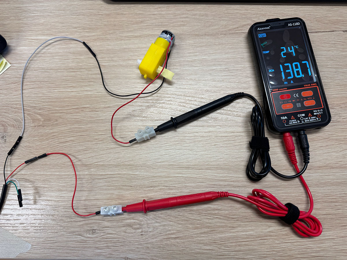
For safety, we first selected the highest current range on the multimeter, which was 10A. Since the reading was much lower than that, we were then able to switch to the 200 mA range in order to obtain a more precise measurement.
The measured current consumption was approximately 135 mA. This value represents the motor consumption under normal test conditions, without a significant mechanical load.
This small test was useful to better understand the behavior of the motor and to estimate the electrical requirements of the system. Measuring the consumption of an output device is especially important when planning a project, since it helps determine whether the chosen power supply and electronics are appropriate for reliable operation.
High quality video available on my YouTube channel ↗️.
Power calculation
P = V · I
- P (Power): The amount of electrical energy consumed by the device, measured in watts (W).
- V (Voltage): The electrical potential difference supplied to the device, measured in volts (V).
- I (Current): The flow of electric charge through the device, measured in amperes (A).
In simple terms, power is the result of how much voltage is applied and how much current the device draws.
To estimate the motor power consumption, the first measurement was taken under normal operating conditions, without mechanical load. In this case, the motor drew an approximate current of 135 mA with a supply voltage of 5.131 V. By applying the power formula P = V · I, the resulting power consumption is approximately 0.69 W, which represents the motor behavior under no-load conditions.
A second measurement was then taken while applying mechanical resistance to the motor shaft, simulating a more realistic load condition. In this case, the current increased to 211 mA. Repeating the same calculation, the power consumption rises to approximately 1.08 W. This increase is consistent with the typical behavior of DC motors, since a higher mechanical load requires more torque, which in turn increases the current draw and overall power consumption.
Power consumption of a RGB LED strip (WS2812)
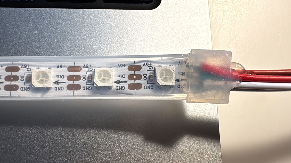
For this test, a WS2812B addressable LED strip with a total of 60 LEDs was used. Each LED integrates its own control circuitry together with the three color channels (red, green, and blue), making it possible to control both color and brightness individually through a single digital data line.
At the hardware level, each pixel includes small SMD components such as resistors and capacitors, which contribute to the overall stability of the system. In particular, these capacitors work as decoupling elements, helping to stabilize the power supply and prevent erratic behavior. As stated in the Adafruit NeoPixel documentation ↗️, in the case of LED strips these capacitors are already integrated, so it is not necessary to add extra components between each LED.
The connection is simple and only requires three signals: power (5V), ground (GND), and a digital data signal (DIN). In this case, the strip was connected directly to a Seeed XIAO RP2040, using pin D1 as the data output.
Although many guides recommend adding a series resistor between the microcontroller and the data input of the strip to improve signal integrity and protect the first LED, usually with values between 300Ω and 500Ω, in this setup it was not necessary to include it, since the strip worked reliably with short connections and without interference.
WS2812B LED Strip Pin Connection
| LED Strip Pin | Connected to XIAO RP2040 | Function |
|---|---|---|
| +5V | 5V | Power supply |
| DIN | D1 | Digital data signal input |
| GND | GND | Ground |
On the software side, a simple program was developed using the Adafruit NeoPixel library to control the strip. The code defines both the control pin (D1) and the total number of LEDs (60). In the setup() function, the strip is initialized, the brightness level is set, and all LEDs are turned on in red using a loop. Finally, the data is sent to the strip using the show() function, while the loop() function remains empty because this test only required a fixed state without animations.
This approach makes modifications very easy, since changing the number of active LEDs, the brightness level, or the RGB values only requires small adjustments in the code. This makes experimentation easier and allows multiple tests to be carried out, both visually and in terms of power consumption analysis.
Arduino code · 01ledstrip1.ino Show code
Several tests were carried out by varying the number of active LEDs, the brightness level, and the displayed color. The following table summarizes the obtained results:
Measurements
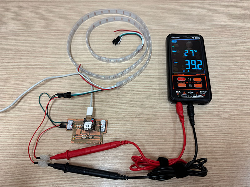
Base consumption (no LEDs ON)
| Condition | Current (mA) | Power (W) |
|---|---|---|
| Strip powered, LEDs OFF | 39.2 | 0.200 |
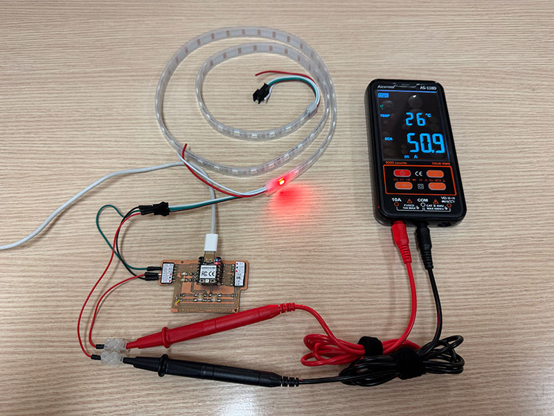
1 LED at full brightness (255)
| Color | Current (mA) | Power (W) |
|---|---|---|
| Red | 50.9 | 0.260 |
| Green | 51.3 | 0.262 |
| Blue | 51.2 | 0.261 |
| White | 74.5 | 0.380 |
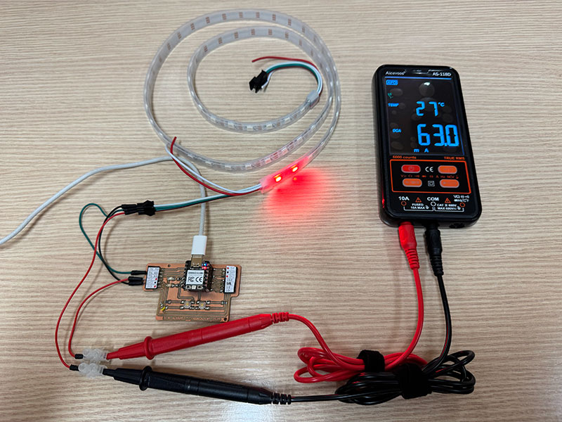
2 LEDs at full brightness (255)
| Color | Current (mA) | Power (W) |
|---|---|---|
| Red | 63.0 | 0.321 |
| Green | 63.4 | 0.323 |
| Blue | 63.3 | 0.323 |
| White | 110.5 | 0.564 |
60 LEDs at low brightness (25)
| Color | Current (mA) | Power (W) |
|---|---|---|
| Red | 108.4 | 0.553 |
| Green | 109.3 | 0.557 |
| Blue | 108.8 | 0.555 |
| White | 248.8 | 1.269 |
60 LEDs at medium brightness (100)
| Color | Current (mA) | Power (W) |
|---|---|---|
| Red | 310.6 | 1.584 |
| Green | 316.5 | 1.614 |
| Blue | 314.3 | 1.603 |
| White | 625.8 | 3.192 |
60 LEDs at high brightness (200)
| Color | Current (mA) | Power (W) |
|---|---|---|
| Red | 501.8 | 2.559 |
| Green | 505.8 | 2.579 |
| Blue | 504.9 | 2.575 |
| White | 851.3 | 4.342 |
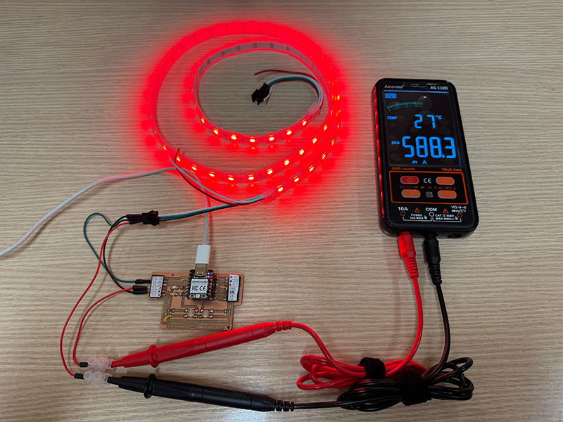
60 LEDs at maximum brightness (255)
| Color | Current (mA) | Power (W) |
|---|---|---|
| Red | 588.3 | 3.000 |
| Green | 576.5 | 2.940 |
| Blue | 570.9 | 2.911 |
| White | 935.7 | 4.772 |
These measurements show that the power consumption of the WS2812B LED strip depends not only on the number of active LEDs, but also on the selected color and the brightness level. As expected, the current increases progressively when more LEDs are turned on and when the brightness value is raised.
An important point is that even with 0 LEDs turned on, the system still shows a base current consumption of 39.2 mA. This happens because both the XIAO RP2040 and the LED strip remain powered, even if no light is being emitted.
Comparing colors, red, green, and blue show very similar values, since each of them activates only one internal channel of the LED. In contrast, white produces a much higher consumption because it combines the three RGB channels at the same time, resulting in the highest current and power values in all the tests.
Overall, the results make it clear that brightness has a strong impact on power consumption, especially when all 60 LEDs are active. This is particularly visible in the white tests, where the measured power reaches almost 4.8 W at full brightness.
Document your work on the group work page and reflect on your individual page what you learned.
This week I have learned not only how to control different output devices, but also how to better understand their electrical behavior in real conditions. Through the tests performed, I have understood how a signal generated by the microcontroller is translated into physical actions such as light or movement, and the importance of controlling these devices precisely through code.
In addition, I learned how to correctly measure power consumption by connecting the multimeter in series and selecting the appropriate range, which allowed me to observe how consumption varies depending on the device’s behavior. All of this helped me understand the importance of proper power supply and system dimensioning in an electronic project, bringing me closer to developing interactive systems for my final project.
Individual assignment
Add an output device to a microcontroller board you've designed and program it to do something
RGB LED strip (WS2812)
Following the code and tests carried out during the group assignment with the LED strip, and taking advantage of the fact that my PCB (designed in W06 ↗️ and made in W08 ↗️) includes two buttons, I developed a new program to interact with the strip and make it respond to these inputs.
In this case, I start from an initial state where all LEDs are turned off. From there, one of the buttons is used to change the lighting state in a cyclic way: when pressed once, all LEDs turn red; when pressed again, they change to green; and with a third press, they turn off again, repeating this behavior in a loop.
The second button is used to control the brightness of the strip. Each press increases the brightness level in several steps, from a low value up to the maximum (255), allowing an easy observation of how this parameter affects both the light intensity and the power consumption.
Pin connection
| Component / Pin | Connected to XIAO RP2040 | Function |
|---|---|---|
| WS2812B +5V | 5V | Power supply |
| WS2812B DIN | D1 (through 220Ω resistor) | Digital data signal input |
| WS2812B GND | GND | Ground |
| Button 1 | D4 | Change LED state: OFF → Red → Green → OFF |
| Button 2 | D6 | Change brightness level |
With this exercise, in addition to controlling an output device, I combine digital inputs (buttons) with state management and parameter control, creating a more dynamic interaction.
Arduino code · 01ledstrip2colorbright.ino Show code
High quality video available on my YouTube channel ↗️.
Micro SERVO 9g SG90
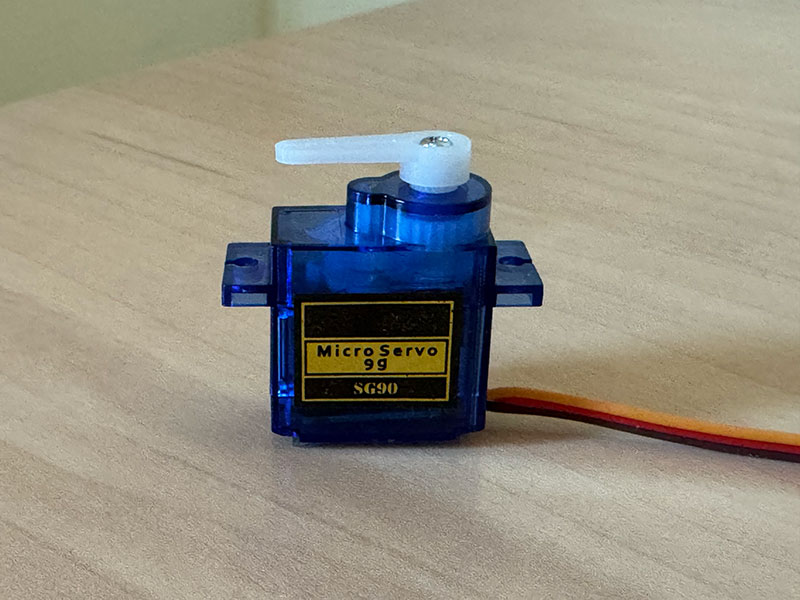
A servo motor is an actuator that allows precise control of the angular position of a shaft. Unlike a conventional motor, it does not rotate continuously, but instead moves to a specific angle depending on the signal it receives. This signal is based on PWM (Pulse Width Modulation), which is generated by the microcontroller.
In this case, an SG90 servo was used, a very common micro servo in electronics and prototyping. This type of servo has a theoretical motion range between 0° and 180°, although in practice this range may vary slightly depending on the model and its internal tolerances.
The servo has three wires: power, ground, and signal. The red wire is connected to 5V, the brown wire to GND, and the orange wire to the digital pin that generates the PWM signal. It is important that the ground of the servo is connected to the ground of the microcontroller so that the signal works correctly.
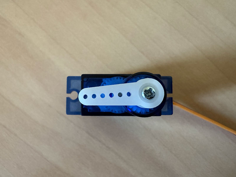
During the first tests, it was observed that the servo was not covering its full range of motion and only reached approximately 90°. This behavior was caused by the fact that the Servo library uses a default PWM signal range that does not always match the full range the servo can interpret. To solve this, the pulse range was adjusted using the attach(pin, 500, 2400) function, which made it possible to unlock almost the full movement range of the servo.
Automatic Servo Movement
In the first test, the servo was programmed to move automatically between three positions: 0°, 90°, and 180°, with a pause between each one. This made it possible to understand how the servo position is controlled using the write() function.
This example shows that the servo does not move continuously by default, but instead travels directly to the commanded angle and stays in that position until it receives a new instruction. It was a simple and effective way to verify the behavior of the actuator and confirm that the full range of movement was available after adjusting the PWM pulse range.
Arduino code · 02servoAuto.ino Show code
Pin connection
| Component / Pin | Connected to XIAO RP2040 | Function |
|---|---|---|
| Servo VCC (Red) | 5V | Power supply |
| Servo Signal (Orange) | D1 (GPIO27) | PWM signal for position control |
| Servo GND (Brown) | GND | Ground reference |
| Push Button | D4 (GPIO6) | Input signal (position control trigger) |
Servo Control Using a Button
In the second test, the servo movement was no longer automatic and instead responded to the interaction with a push button. Each time the button was pressed, the servo advanced to the next position in a sequence: 0° → 90° → 180° → 0°.
The button was connected to pin D4 (GPIO6) and configured using INPUT_PULLUP, so it worked with inverted logic, reading LOW when pressed. This setup made it possible to detect each button press and use it to change the servo position step by step.
This example introduced the concept of interactive control, where the movement of the servo depends on an external input rather than running automatically. It also allowed the use of state-based logic to manage different angular positions with a single user action, making the behavior more dynamic and easier to control.
Arduino code · 02servoButton.ino Show code
High quality video available on my YouTube channel ↗️.
High quality video available on my YouTube channel ↗️.
TM1637 Display
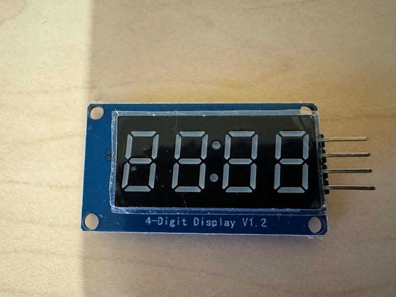
In my PCB design, the pins corresponding to I2C communication (SDA and SCL) are already occupied by other components (LEDs and buttons), which makes it difficult to test other displays that rely on this protocol, such as many OLED or LCD modules. This became a small limitation during this week’s work, since a large number of display modules are designed to communicate through I2C.
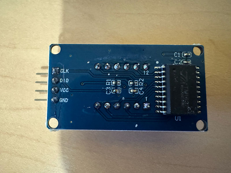
For that reason, I decided to work with a TM1637-based 4-digit 7-segment display, which does not require I2C and instead uses a simplified two-wire interface through CLK and DIO. This made it much easier to integrate into my existing board without having to redesign the PCB or reassign already occupied pins.
The display itself is a simple but very practical output device for showing numerical information clearly. It has 4 digits, and each digit is made up of 7 individual LED segments that combine to represent numbers from 0 to 9. One of the main advantages of this module is that the TM1637 driver handles the low-level control internally, so from the microcontroller side it is much easier to send data and manage what is shown on screen.
The 4-digit 7-segment display module uses the TM1637 driver, which simplifies control using a 2-wire interface (CLK and DIO). The module was powered at 3.3V to ensure compatibility with the Seeed XIAO RP2040 logic levels.
Pin connection
| Display Pin | Connected To (XIAO RP2040) | Function |
|---|---|---|
| GND | GND | Ground |
| VCC | 3V3 | Power supply |
| DIO | D1 | Data signal |
| CLK | D0 | Clock signal |
To test the display, I wrote a simple example program that shows numbers made of the same repeated digit: 0000, 1111, 2222, and so on up to 9999, changing once every second and then starting again from the beginning. The code works by running a loop from 0 to 9 and multiplying each value by 1111, which creates the repeated pattern across the four digits.
This was a very useful first test because it allowed me to confirm that all the segments were working correctly and also helped me understand more clearly how to send data to the display from the microcontroller.
Arduino code · 02TMdisplay1.ino Show code
High quality video available on my YouTube channel ↗️.
Output devices testing for my final project
Building on the input device tests from the previous week, where I validated the goal detection using the IR sensor, I have now started integrating output devices to generate a visible response in the system.
In this iteration, I added a WS2812B LED strip and a TM1637 display, so that when a goal is detected, the system not only reacts with a light animation but also updates and shows the score. This transforms the system from simple detection into a more interactive and meaningful experience.
Final project development - Week10 sectionOriginal code files for this documentation
Files for download
- LED strip arduino code testing (01ledstrip1.ino) INO · 0,6 Kb
- LED strip arduino code testing (01ledstrip2colorbright.ino) INO · 2 Kb
- Servo Automatic movement (02servoAuto.ino) INO · 0,3 Kb
- Servo Automatic movement (02servoButton.ino) INO · 0,9 Kb
- TM display test (02TMdisplay1.ino) INO · 0,3 Kb
Week questions/tasks
Final reflection
This has been a very interesting week, especially because I was able to take a step further in my final project, moving from simply reading information to generating a physical response in the system. Understanding how a microcontroller can control devices such as LEDs, servos, and displays, and transform code into real actions, has been a significant challenge for me due to my lack of background in electronics.
One of the most valuable aspects has been understanding the electrical behavior of output devices, especially current consumption and its relationship with parameters such as brightness, the number of active elements, or mechanical load. This has helped me realize the importance of proper power supply dimensioning and designing more stable and realistic systems.
In addition, I have improved the way I program these systems, moving from simple solutions based on delay() to more advanced approaches using millis(), which allows managing multiple events simultaneously. I also worked with state-based logic and edge detection, making the interaction much more precise and controlled.
Overall, this week has allowed me to evolve from isolated tests to more complete and interactive systems, bringing me much closer to the real development of my final project.
Credits
I would like to thank to Javier ↗️ (FabLab Ponferrada Manager) for facilitating our access to the fablab and lend us material.
And to my wife, for her help in recording the videos.
All texts were written in Spanish and translated into English using Google Translate and ChatGPT.