Final project
Development by weeks
Week 01: baby sketches
Dates: 21/01/2026 - 27/01/2026
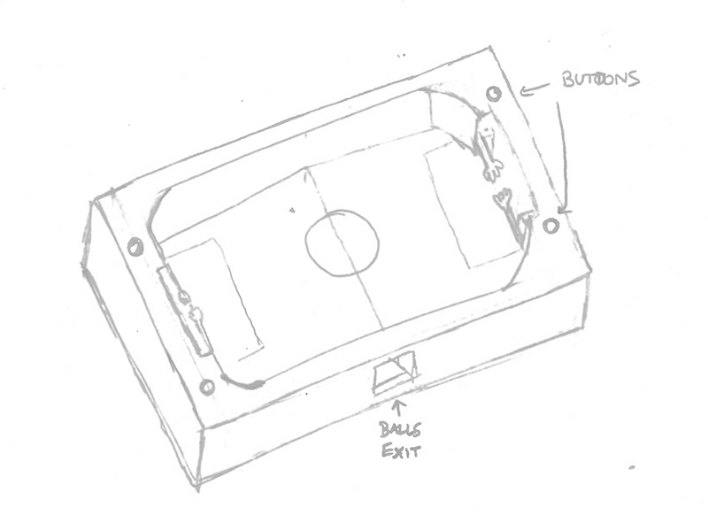
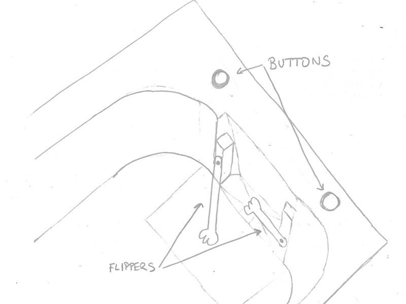
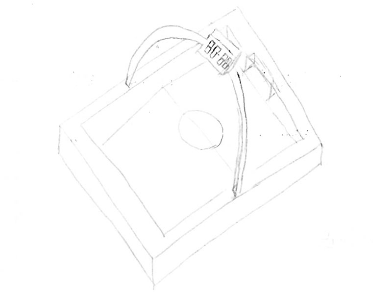
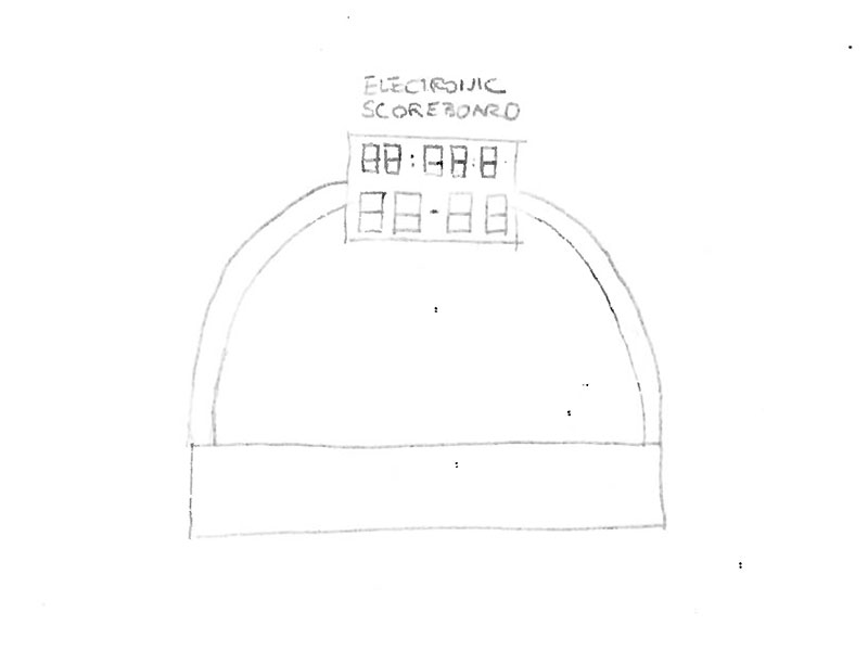
During this week, I created several hand sketches to explore the layout, proportions, and main elements of the game. This work helped me clarify the concept and set a clear starting point for the future development of the project.
Week 02: 3D sketch
Dates: 28/01/2026 - 3/02/2026
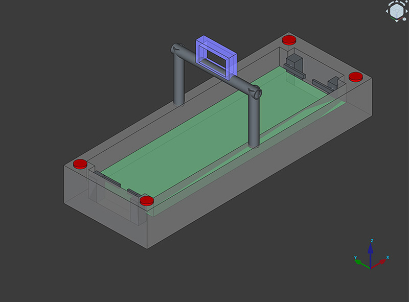
I started shaping my final project by defining its main idea and visual structure. I created several 2D sketches to explore the layout and key components, and from there I began translating those ideas into 3D for the first time. I modeled the overall concept and focused on designing one of the main elements of the project, a hand-shaped flipper, first in 2D and then as a functional 3D part. This process helped me understand how the project could actually be built and how its parts might move and interact, turning an initial idea into something much more concrete
Week 04: Embedded Programming
Dates: 11/02/2026 - 17/02/2026
PinSocc Ball match display
The main objective was to develop a functional scoreboard system for my final project PinSocc Ball, simulating the behavior of a real football match display.
I started from the example sketches provided in the QPAD-XIAO repository: the RGB LED control example and the six capacitive touch buttons example. First, I made sure we fully understood how they worked. Using the Serial Monitor, I verified which touch pad corresponded to each GPIO pin, and confirmed that the RGB LED logic was active LOW.
Once inputs and outputs were clear, I began extending the code. The first step was implementing a 3-minute countdown timer. The timer starts when touching one control pad, pauses if touched again, and can be reset using another pad — but only when it is stopped.
After the timer was stable, I added the scoreboard logic. Each time the corresponding touch control is pressed, the score increases by one goal for that team — as long as the timer is running. In my project, this simulates that the goal sensor inside the football goal has detected a goal. This prevents goals from being counted while the game is paused.
Touch controls
| Button | Function |
|---|---|
| 0 | Start / Pause the timer |
| 1 | Reset the timer (only if paused) |
| 3 | Add one goal to the Home team (only if timer is running) |
| 4 | Add one goal to the Away team (only if timer is running) |
The development process was incremental. I began with simple hardware examples and gradually added logic and state control until we achieved a complete and stable scoreboard system for PinSocc Ball.
Full time & High quality video available on my YouTube channel ↗️.
Arduino code · timer-score.ino Show code
// Code generated with the help of AI from the prompt described in the documentation; manually reviewed and adapted.

#include
#include
#include

// ------------------------- Display / Pantalla -------------------------
#define SCREEN_WIDTH 128
#define SCREEN_HEIGHT 64
#define OLED_RESET    -1
#define OLED_ADDR     0x3C

Adafruit_SSD1306 display(SCREEN_WIDTH, SCREEN_HEIGHT, &Wire, OLED_RESET);

// ------------------------- Fast IO fallback -------------------------
#ifndef digitalReadFast
  #define digitalReadFast digitalRead
#endif
#ifndef digitalWriteFast
  #define digitalWriteFast digitalWrite
#endif
#ifndef pinModeFast
  #define pinModeFast pinMode
#endif

// ------------------------- RGB LED (active LOW) / LED RGB (activo LOW) -------------------------
const uint8_t LED_R = 17;
const uint8_t LED_G = 16;
const uint8_t LED_B = 25;

inline void ledOn(uint8_t pin)  { digitalWriteFast(pin, LOW);  } // active LOW
inline void ledOff(uint8_t pin) { digitalWriteFast(pin, HIGH); }

void ledsAllOff() {
  ledOff(LED_R);
  ledOff(LED_G);
  ledOff(LED_B);
}

// ------------------------- Touch pins / Pines táctiles -------------------------
const uint8_t TOUCH_PINS[6] = { 3, 4, 2, 27, 1, 26 };

const uint16_t THRESHOLD = 6;
const uint16_t TOUCH_MAX_COUNT = 2000;
const uint32_t TOUCH_LOCKOUT_MS = 180;
uint32_t lastTouchTriggerMs[6] = {0,0,0,0,0,0};

uint16_t readTouchCount(uint8_t pin) {
  // Discharge / Descargar
  pinModeFast(pin, OUTPUT);
  digitalWriteFast(pin, LOW);
  delayMicroseconds(5);

  // Measure rise / Medir subida
  pinModeFast(pin, INPUT_PULLUP);

  uint16_t count = 0;
  while (digitalReadFast(pin) == LOW && count < TOUCH_MAX_COUNT) {
    count++;
  }
  return count;
}

bool touchPressed(uint8_t idx) {
  uint16_t v = readTouchCount(TOUCH_PINS[idx]);
  if (v <= THRESHOLD) return false;

  uint32_t now = millis();
  if (now - lastTouchTriggerMs[idx] < TOUCH_LOCKOUT_MS) return false;

  lastTouchTriggerMs[idx] = now;
  return true;
}

// ------------------------- Timer logic / Lógica temporizador -------------------------
const uint32_t START_TIME_MS = 10UL * 1000UL; // 10 seconds / 10 segundos
// const uint32_t START_TIME_MS = 1UL * 60UL * 1000UL; // 1 minute / 1 minuto

uint32_t remainingMs = START_TIME_MS;
bool isRunning = false;
bool isGameOver = false;
uint32_t lastUpdateMs = 0;

// ------------------------- Scoreboard / Marcador -------------------------
uint16_t goalsHome = 0; // Local
uint16_t goalsAway = 0; // Visitante

// Button mapping (indices in TOUCH_PINS)
// Button 3 -> index 3 (pin 27)  -> Home
// Button 4 -> index 4 (pin 1)   -> Away
const uint8_t BTN_HOME_SCORE = 3;
const uint8_t BTN_AWAY_SCORE = 4;

// ------------------------- Game Over strobe / Estrobo -------------------------
uint32_t strobeLastMs = 0;
uint8_t strobeStep = 0;
const uint32_t STROBE_STEP_MS = 90;

// ------------------------- Render -------------------------
void renderMainScreen() {
  display.clearDisplay();

  // IMPORTANT: force white text every frame / Forzar texto blanco cada frame
  display.setTextColor(SSD1306_WHITE);
  display.setTextWrap(false);

  // Title
  display.setTextSize(1);
  display.setCursor(0, 0);
  display.print("Timer + Score");

  // Timer (fixed position)
  uint32_t totalSeconds = remainingMs / 1000UL;
  uint32_t minutes = totalSeconds / 60UL;
  uint32_t seconds = totalSeconds % 60UL;

  char timeBuf[8];
  snprintf(timeBuf, sizeof(timeBuf), "%lu:%02lu",
           (unsigned long)minutes, (unsigned long)seconds);

  display.setTextSize(2);
  display.setCursor(28, 16);   // fixed
  display.print(timeBuf);

  // Score (fixed position)
  char scoreBuf[12];
  snprintf(scoreBuf, sizeof(scoreBuf), "%u-%u", goalsHome, goalsAway);

  display.setTextSize(2);
  display.setCursor(36, 36);   // fixed
  display.print(scoreBuf);

  // Footer
  display.setTextSize(1);
  display.setCursor(0, 56);
  if (isRunning) display.print("B0:Pause B3:+L B4:+V");
  else          display.print("B0:Start  B1:Reset");

  display.display();
}

void renderGameOverScreen() {
  display.clearDisplay();

  display.setTextColor(SSD1306_WHITE);
  display.setTextWrap(false);

  display.setTextSize(2);
  display.setCursor(10, 8);
  display.print("GAME OVER");

  char scoreBuf[12];
  snprintf(scoreBuf, sizeof(scoreBuf), "%u-%u", goalsHome, goalsAway);

  display.setTextSize(2);
  display.setCursor(36, 30);
  display.print(scoreBuf);

  display.setTextSize(1);
  display.setCursor(12, 56);
  display.print("Press BTN1 to reset");

  display.display();
}

// ------------------------- Setup -------------------------
void setup() {
  Serial.begin(115200);
  delay(80);

  // LEDs
  pinModeFast(LED_R, OUTPUT);
  pinModeFast(LED_G, OUTPUT);
  pinModeFast(LED_B, OUTPUT);
  ledsAllOff();

  // Touch pins
  for (uint8_t i = 0; i < 6; i++) {
    pinModeFast(TOUCH_PINS[i], INPUT_PULLUP);
  }

  // OLED
  Wire.begin();
  if (!display.begin(SSD1306_SWITCHCAPVCC, OLED_ADDR)) {
    Serial.println("SSD1306 init failed (addr 0x3C?) / Fallo init SSD1306");
    while (1) { delay(10); }
  }

  // Optional: set contrast / opcional
  display.ssd1306_command(SSD1306_SETCONTRAST);
  display.ssd1306_command(0xFF);

  remainingMs = START_TIME_MS;
  isRunning = false;
  isGameOver = false;
  goalsHome = 0;
  goalsAway = 0;
  lastUpdateMs = millis();

  Serial.println("Ready / Listo");
  renderMainScreen();
}

// ------------------------- Loop -------------------------
void loop() {
  uint32_t now = millis();

  bool btn0 = touchPressed(0);
  bool btn1 = touchPressed(1);
  bool btnHome = touchPressed(BTN_HOME_SCORE);
  bool btnAway = touchPressed(BTN_AWAY_SCORE);

  // GAME OVER state
  if (isGameOver) {
    if (btn1) {
      isGameOver = false;
      isRunning = false;
      remainingMs = START_TIME_MS;
      goalsHome = 0;
      goalsAway = 0;
      ledsAllOff();
      renderMainScreen();
    } else {
      if (now - strobeLastMs >= STROBE_STEP_MS) {
        strobeLastMs = now;
        ledsAllOff();
        if (strobeStep == 0) ledOn(LED_R);
        if (strobeStep == 1) ledOn(LED_G);
        if (strobeStep == 2) ledOn(LED_B);
        strobeStep = (strobeStep + 1) % 3;
      }
    }
    return;
  }

  // BTN0 toggle
  if (btn0) {
    isRunning = !isRunning;
    lastUpdateMs = now;
    renderMainScreen();
  }

  // BTN1 reset only if paused
  if (btn1 && !isRunning) {
    remainingMs = START_TIME_MS;
    goalsHome = 0;
    goalsAway = 0;
    renderMainScreen();
  }

  // Scoring only while running
  if (isRunning) {
    if (btnHome) { goalsHome++; renderMainScreen(); }
    if (btnAway) { goalsAway++; renderMainScreen(); }
  }

  // Timer update
  if (isRunning) {
    uint32_t dt = now - lastUpdateMs;
    lastUpdateMs = now;
    if (dt > 1000UL) dt = 1000UL;

    if (remainingMs > dt) remainingMs -= dt;
    else remainingMs = 0;

    static uint32_t lastRefresh = 0;
    if (now - lastRefresh >= 150) {
      lastRefresh = now;
      renderMainScreen();
    }

    if (remainingMs == 0) {
      isRunning = false;
      isGameOver = true;
      strobeLastMs = now;
      strobeStep = 0;
      ledsAllOff();
      renderGameOverScreen();
    }
  } else {
    lastUpdateMs = now;
  }
}
Files for download
- Time & Score arduino code (timer-score.ino) INO · 7 Kb
Week 05: 3D Scanning and Printing
Dates: 18/02/2026 - 24/02/2026
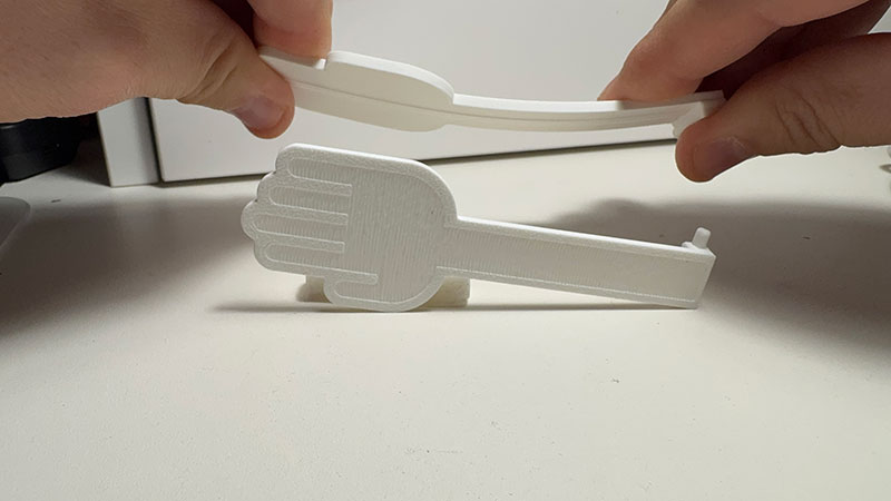
Taking advantage of 3D printing, this week I decided to print a part for my final project. In this case, it's the handflipper that will push the ball when activated by a button.
Since this part, besides moving quickly, will have direct impact with the ball, 3D printing has been very useful for starting to consider the dimensions, hardness, and elasticity needed for proper functioning.
The design was the one I created in week 2. After printing it, I realized that it might need more thickness and rigidity, but until I know what material the ball will be made of, no further testing will be necessary.
Files for download
- HandFlipper (04FreeCAD_hand.FCStd) FCStd · 165 Kb
- HandFlipper (04FreeCAD_hand2.stl) STL· 441 Kb
- HandFlipper (04FreeCAD_hand.dxf) DXF · 476 Kb
Week 06
Dates: 25/02/2026 - 3/03/2026
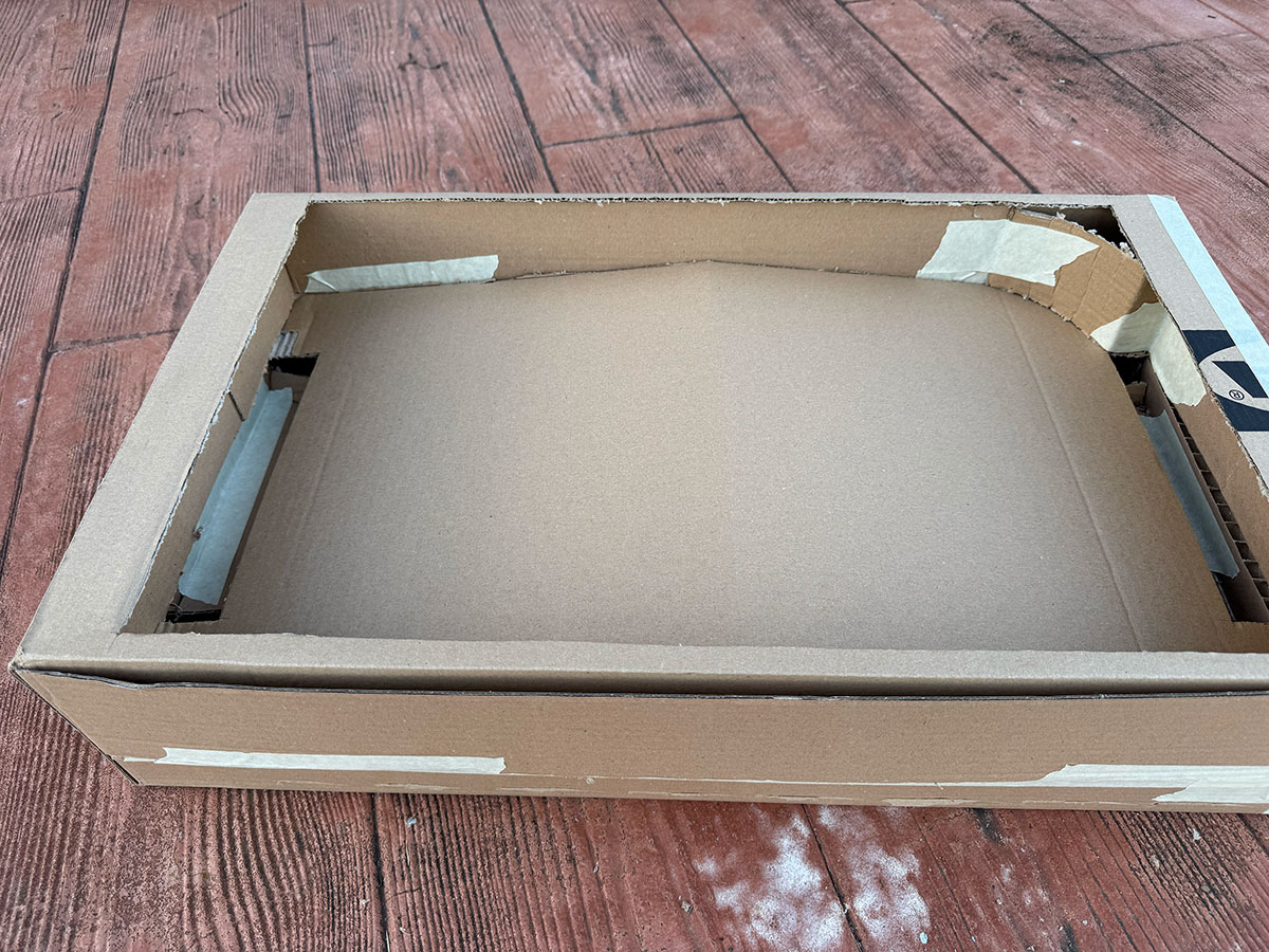
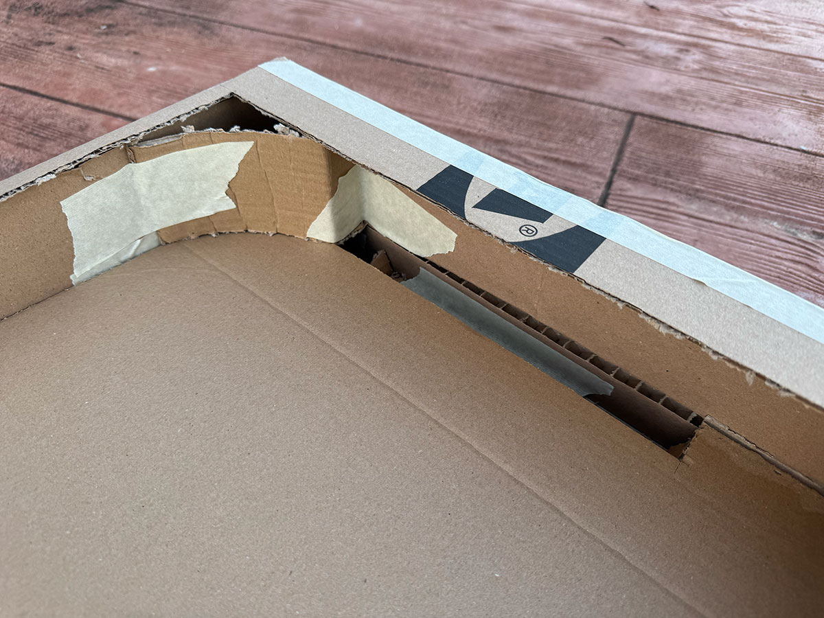
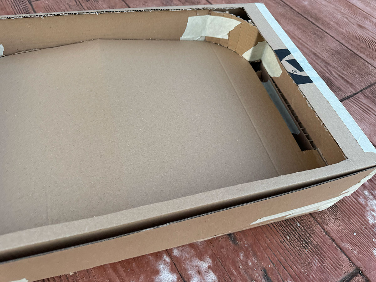
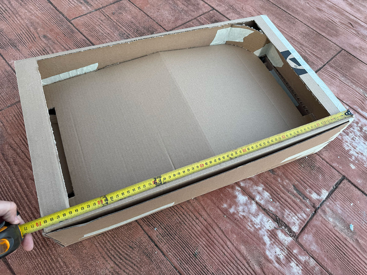
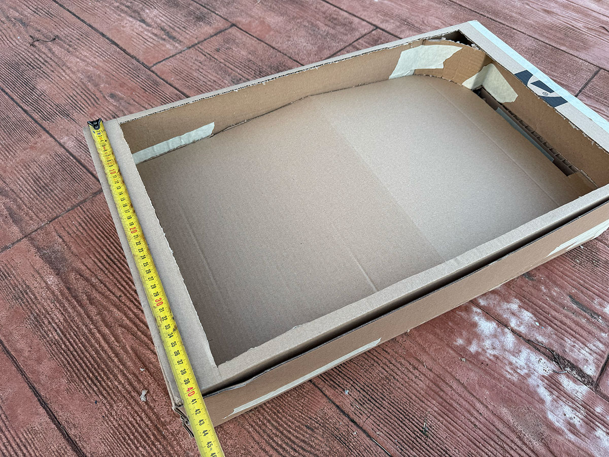
Although it has nothing to do with this week's theme (electronic design), this week I made a first cardboard model in order to start analyzing possible measurements, problems and solutions when carrying out my final project.
One of the things I did was divide it into two parts: the top part will be the playing area, and the bottom part will house the ball routing system so it can return to the starting position. There's also plenty of space to accommodate all the electronics.
Size: 70x40 cm
High quality video available on my YouTube channel ↗️.
Week 07
Dates: 4/03/2026 - 19/03/2026
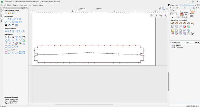
This week's Computer-Controlled Machining class, specifically the use of a CNC machine, is perfect for designing and milling wooden pieces, like the cardboard model I made last week. Although I haven't had time to actually do it, it's given me time to think about how to make both the top and bottom parts, as well as the playing surface.
I hope to be able to do it soon, although I know it won't be finalized until I know what input and output devices I'll need. It's essential to consider these when assembling everything, ensuring each component is in its correct place and properly secured.
Week 08
Dates: 11/03/2026 - 17/03/2026
This week, Electronics Production is going the same way as last week. I can't make any progress in manufacturing the PCBs I need because I still don't know which input and output devices I'll require. It has, however, been useful for manufacturing a basic PCB to run tests for the final project in the coming weeks.
Week 09
Dates: 18/03/2026 - 24/03/2026
RCWL-0516 microwave sensor
Taking advantage of the input devices tested during Week 09, specifically the RCWL-0516 microwave sensor and the IR road tracking sensor, I decided to run some experiments related to my final project. The goal was to simulate a goalpost and test whether the sensor could detect when a ball enters the goal.
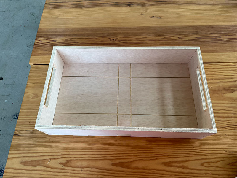
To do this, I built a simple setup using a small cardboard box to represent the goal. I placed the sensor inside the box and started testing how it reacted when introducing a ball.
I began by testing the RCWL-0516 microwave sensor. I made a small modification to the Arduino code so that instead of printing “1” in the Serial Monitor when motion is detected, it displays the message “GOAL!”.
After running the code, I noticed that even with the sensor placed inside the box, it was still sensitive to movements outside. For example, every time I moved my hand to place the ball into the goal, the sensor detected that motion. Once I stayed still and confirmed that the sensor output was zero, I dropped the ball into the goal and the sensor correctly triggered the “GOAL!” message. However, when I tried to pick up the ball to repeat the test, the sensor detected movement again.
Although the sensor is able to detect the ball successfully, it turns out to be too sensitive for this application. In my “PinSocc Ball” project, the sensor would be placed inside the goal, below the playing field. Even if it is not directly visible or exposed, it would still detect any nearby movement, since that is exactly what it is designed to do.
High quality video available on my YouTube channel ↗️.
Arduino code · 05RCWL2.ino Show code
// Code generated with the help of AI from the prompt described in the documentation; manually reviewed and adapted.
const int sensorPin = D1;

void setup() {
  Serial.begin(115200);
  pinMode(sensorPin, INPUT);
  delay(1000);
  Serial.println("RCWL test start");
}

void loop() {
  int state = digitalRead(sensorPin);

  if (state == HIGH) {
    Serial.println("GOAL!");
  } else {
    Serial.println("0");
  }

  delay(500);
}
For this reason, I concluded that this sensor is not suitable for use in my Final Project.
IR road tracking sensor
Next, I moved on to testing the IR road tracking sensor, repeating the same setup as in the previous experiment.
I modified the Arduino code I had used before. In this case, I only read the digital output of the sensor so that it displays the message “GOAL!! ⚽” whenever a detection is triggered.
After several tests, I realized that due to the speed at which the ball falls, I needed to significantly reduce the delay value. I finally set it to 50 ms, which provided a reliable response.
High quality video available on my YouTube channel ↗️.
Arduino code · 04IR2.ino Show code
// Code generated with the help of AI from the prompt described in the documentation; manually reviewed and adapted.
// Pin definition
const int digitalPin = D1;  // Sensor D0 -> XIAO D1 (P27)

int lastState = 1; // Initial state (no detection)

void setup() {
  Serial.begin(115200);
  pinMode(digitalPin, INPUT);

  Serial.println("IR Goal Detection System");
}

void loop() {
  int currentState = digitalRead(digitalPin);

  // Detect transition (object passing)
  if (lastState == 1 && currentState == 0) {
    Serial.println("GOAL!! ⚽");
  } else {
    // No detection
    Serial.println("0");
  }

  // Update previous state
  lastState = currentState;

  delay(50);
}
Based on these tests, I confirmed that an IR-based sensor is the right approach to detect goals in each goalpost. In this case, the sensor will be placed under the playing field, at the point where the ball drops into the rails that return it back into play.
This specific module may not be the optimal final solution, but it clearly shows that I need an IR barrier-type sensor for my Final Project.
Files for download
- RCWL test code (05RCWL2.ino) INO · 0.5 Kb
- IR test code (04IR2.ino) INO · 0.5 Kb
Week 10
Dates: 25/03/2026 - 31/03/2026
Goal detection + output devices integration
After validating in Week 09 that the IR sensor was a reliable solution to detect when the ball enters the goal, the next step during Week 10 was to start working with output devices and transform that detection into a visible and meaningful response.
Taking advantage of the tests I carried out this week with different output devices, especially the WS2812B RGB LED strip and the TM1637 4-digit display, I began integrating them into my final project.
Version 1 – Sensor + LED strip
In the first iteration, the goal was simple: create an immediate visual feedback when a goal is detected.
Using the same IR sensor logic developed in Week 09, I connected a WS2812B RGB LED strip and programmed a basic animation:
- Green color (associated with a goal)
- Fast blinking effect
- Duration of around 2 seconds
To detect the goal, I used a state change (edge detection), which prevents multiple triggers while the ball remains inside the goal area.
At this point, I also started replacing delay() with millis(), allowing me to control timing without blocking the system. This is important because the final project will need to manage multiple events at the same time.
With this setup, the system already behaves as a reactive goal indicator, providing immediate feedback to the player.
Pin Connection
| Component | Pin | Connected to XIAO RP2040 | Function |
|---|---|---|---|
| IR Sensor | OUT | D2 | Goal detection |
| IR Sensor | VCC | 3.3V | Power |
| IR Sensor | GND | GND | Ground |
| WS2812B LED strip | DIN | D1 | LED control |
| LED strip | 5V | 5V | Power |
| LED strip | GND | GND | Ground |
High quality video available on my YouTube channel ↗️.
Arduino code · 03LEDgoal.ino Show code
Version 2 – Sensor + LED strip + display
Once the visual feedback was working properly, I moved to the next step: adding information to the system.
Using the TM1637 display tested during Week 10, I implemented a simple scoring system. Now, every time a goal is detected:
- The score increases by one
- The value is displayed on the screen
- The LED animation is triggered
- The display briefly shows "GOAL" before returning to the score
I also added a reset button to bring the score back to zero, introducing a basic level of user interaction.
With this update, the system evolves from a simple reactive output to a state-based interactive system, capable of remembering and displaying what has happened during the game.
During this integration, I encountered a practical limitation: my PCB only provides two GND pins, which is not enough for the sensor, LED strip, and display at the same time.
To solve this, I used a breadboard as a common ground distribution point, which allowed me to:
- Share GND between all components
- Integrate the LED resistor more cleanly
- Keep the wiring organized and flexible
This kind of workaround reflects a real prototyping situation, where the initial PCB design still needs adjustments before reaching the final version.
Pin Connection
| Component | Pin | Connected to XIAO RP2040 | Function |
|---|---|---|---|
| IR Sensor | OUT | D2 | Goal detection |
| IR Sensor | VCC | 3.3V | Power |
| IR Sensor | GND | GND | Ground |
| WS2812B LED strip | DIN | D1 | LED control |
| WS2812B LED strip | 5V | 5V | Power |
| WS2812B LED strip | GND | GND | Ground |
| TM1637 Display | CLK | D0 | Clock signal |
| TM1637 Display | DIO | D7 | Data signal |
| TM1637 Display | VCC | 5V | Power |
| TM1637 Display | GND | GND | Ground |
| Reset button | Pin | D4 | Reset score |
High quality video available on my YouTube channel ↗️.
Arduino code · 03LEDgoalDisplay.ino Show code
With these two iterations, I moved from simply detecting a goal to building a complete interactive system that reacts, displays information, and keeps track of the game state — a key step towards the final integration of my project.
Hand-Flippers. Dual servo control
After the initial tests carried out during Week 10, where I explored the behavior of the SG90 servo both in automatic mode and controlled by a button, the next step in my final project development was to move towards a more realistic interaction.
In my project PinSocc Ball, the flippers are one of the most important elements, as they are responsible for directly interacting with the ball. For this reason, I needed to evolve from a simple single-servo test to a system capable of controlling two independent servos, simulating the behavior of the left and right flippers of a real pinball machine.
To achieve this, I designed a simple system based on two push buttons, where each one controls its own servo. Every time a button is pressed, the servo performs a fast movement to the hit position and then returns automatically to its resting position, recreating the typical flipper action.
To ensure reliable interaction, I implemented a edge detection logic (HIGH → LOW) instead of continuously reading the button state. This allowed me to detect each press more precisely and avoid repeated triggers while the button remains pressed, significantly improving the stability of the system.
During testing, one of the most interesting findings was that the servo did not always behave as expected when using intermediate values such as 90°. After several experiments, I realized that the actual physical range of the servo in my setup did not perfectly match the theoretical values, so I decided to work with the full range (0–180) to achieve a wider and more suitable movement for the flipper effect.
Another key aspect was the need to invert the movement of one of the servos. In a pinball system, the flippers move in opposite directions, so I configured the second servo in an inverted way by swapping its rest and hit positions. This results in a symmetrical and much more realistic behavior within the game.
Pin Connection
| Component / Pin | Connected to XIAO RP2040 | Function |
|---|---|---|
| Servo 1 (Signal) | D2 (GPIO28) | Controls left flipper movement |
| Servo 1 VCC | 5V | Power supply |
| Servo 1 GND | GND | Ground reference |
| Servo 2 (Signal) | D1 (GPIO27) | Controls right flipper movement (inverted) |
| Servo 2 VCC | 5V | Power supply |
| Servo 2 GND | GND | Ground reference |
| Button 1 | D4 (GPIO6) | Trigger Servo 1 (left flipper) |
| Button 2 | D6 (GPIO0) | Trigger Servo 2 (right flipper) |
With this iteration, the system evolves from a basic servo control test into a more complete interactive system, where the user can independently trigger each flipper. This represents an important step towards the full integration of the mechanical and electronic components in the final project.
High quality video available on my YouTube channel ↗️.
Arduino code · 03_2servos_2buttons.ino Show code
After validating the basic behavior of both flippers, I identified an important limitation in the initial implementation: the use of delay() was blocking the system. This meant that when both buttons were pressed at the same time, one of the servos responded later than the other, breaking the feeling of a real pinball interaction.
High quality video available on my YouTube channel ↗️.
To solve this, I replaced the blocking logic with a non-blocking approach using millis(). Instead of stopping the program while the servo was moving, each flipper now manages its own timing independently. This allows both servos to react simultaneously and smoothly, even when the two buttons are pressed at the same time.
With this improvement, the system becomes much more responsive and closer to a real interactive device, laying a stronger foundation for future features where multiple inputs and outputs need to work in parallel.
High quality video available on my YouTube channel ↗️.
Arduino code · 03_2servos_2buttons_v2.ino Show code
These servos might not be the best for my final project, but they've been useful for testing and giving me a clear starting point for what I might need. I'll probably need faster servos.
Files for download
- IR Goal sensor + LED (03LEDgoal.ino) INO · 2 Kb
- IR Goal sensor + LED + Display (03LEDgoalDisplay.ino) INO · 3 Kb
- Double handflipper (03_2servos_2buttons.ino) INO · 1 Kb
- Double handflipper v2 (03_2servos_2buttons_v2.ino) INO · 3 Kb
Week 11
Dates: 1/04/2026 - 7/04/2026
Networking and Communications scoring screen testing
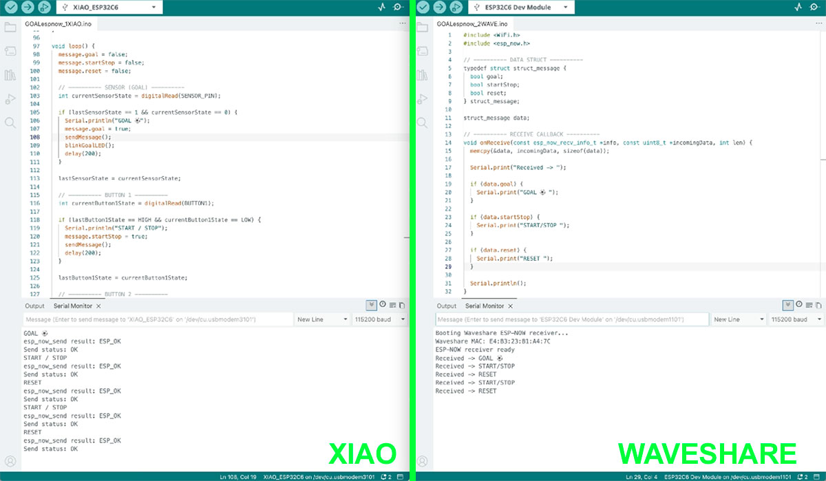
At this stage, I brought the networking work much closer to the final project by developing a complete wireless scoreboard system with two goals.
To achieve this, I used a XIAO ESP32 as the input node, connected to two IR sensors, one on each goal. In this way, the system is able to detect which team has scored at any moment. In addition, two physical buttons were integrated to control the match: one to start or pause the timer, and another one to reset the scoreboard when the game is stopped or finished.
All these events are sent wirelessly through ESP-NOW to a Waveshare ESP32-C6, which acts as the central node. This board receives the information and manages the system logic, updating both the match time and the score in real time.
A 30-second timer was implemented for testing, making sure that goals are only counted while the timer is running, and that reset is only allowed in valid states. On the display, the system shows the remaining time, the message “GOAL” whenever a goal is detected, and the updated score for both teams.
As a visual reinforcement, a 120-LED WS2812B strip was added and divided into two segments, one for each team. Every goal triggers a green blinking effect on the corresponding segment, while during the last 10 seconds all LEDs blink in red. When time runs out, the strip stays solid red until a reset is performed, and at the start of the match a short green start effect indicates that the game has begun.
With this development, I was able to build a fully functional distributed system, where different nodes communicate wirelessly to create a coherent real-time experience, very much aligned with the final goal of the project.
Arduino code XIAO · GOALespnow_1XIAO.ino Show code
Arduino code WAVESHARE · GOALespnow_2WAVE_LCD_LED.ino Show code
High quality video available on my YouTube channel ↗️.
High quality video available on my YouTube channel ↗️.
System wiring and connections
| Element | Type | Connection / Pin | Function |
|---|---|---|---|
| IR Sensor (Visitor goal) | Input | D9 (XIAO ESP32-C6) | Detects goals scored by the visitor team |
| IR Sensor (Local goal) | Input | D2 (XIAO ESP32-C6) | Detects goals scored by the local team |
| Button 1 | Input | D4 (XIAO ESP32-C6) | Start / Stop timer |
| Button 2 | Input | D6 (XIAO ESP32-C6) | Reset match (only when stopped) |
| LED (Local) | Output | D3 (XIAO ESP32-C6) | Visual feedback when local team scores |
| LED (Visitor) | Output | D5 (XIAO ESP32-C6) | Visual feedback when visitor team scores |
| XIAO ESP32-C6 | Node | ESP-NOW (wireless) | Sends events (goals, buttons) to display node |
| Waveshare ESP32-C6 | Node / Output | ESP-NOW (wireless) | Receives data and manages scoreboard logic |
| WS2812B LED Strip (120 LEDs) | Output | GP0 (Waveshare) |
Visual effects: - 0–59 → Local team - 60–119 → Visitor team |
| Powerbank (5V) | Power | Shared supply | Provides power to XIAO and Waveshare boards |
System architecture (Input → Network → Output)
| Stage | Component | Description |
|---|---|---|
| Input | IR Sensors (2 goals) |
Two IR sensors detect goals in each goal area: - Visitor goal → local team scores - Local goal → visitor team scores |
| Input | Push Buttons |
User interaction controls the match: - Start / Stop timer - Reset match (only when stopped or finished) |
| Processing | XIAO ESP32-C6 |
Reads sensor and button inputs, processes events, and generates structured messages (goal, start/stop, reset) |
| Network | ESP-NOW |
Wireless communication protocol used to send data between nodes without requiring Wi-Fi infrastructure |
| Processing | Waveshare ESP32-C6 |
Receives data, manages match logic (timer and score), and controls all outputs in real time |
| Output | Display (Waveshare) |
Shows match information: - Remaining time - Goal notification - Score (local vs visitor) |
| Output | LED Strip (WS2812B) |
Provides visual feedback: - Green blink on goal (per team segment) - Red blinking during last 10 seconds - Solid red at end of match - Green start effect |
| Power | Powerbank (5V) |
Shared power supply for all system components, ensuring portability and independence from external sources |
Files for download
Week 13
Dates: 16/04/2026 - 21/04/2026
Midterm review
Project system diagram
The system diagram gives an overview of how the final project is structured and how all the parts are connected. It is based on a distributed architecture with three ESP32 boards: one central unit and two remote units, one integrated in each goal. The remote boards handle local inputs such as buttons and goal sensors, and control the servos, while the central board receives the data wirelessly using ESP-NOW and updates the display and LED strips to provide visual feedback.
Poster version
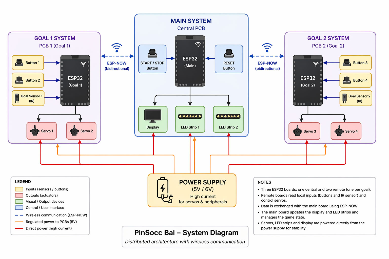
Diagram version
Mermaid CDN by jsDelivr - A CDN for npm and GitHub
Final project tasks
The task list defines all the work required to complete the final project. It is organized into different development phases such as planning, design, fabrication, integration, programming, and finalization. Each phase includes smaller subtasks that help break the project into manageable and trackable steps, making it easier to monitor progress and stay organized.
Schedule
The schedule is presented as a Gantt diagram that shows how the project will be developed over time. Tasks are distributed across the remaining weeks until the final deadline, allowing a clear view of the timeline and workload. This planning helps to track progress, prioritize tasks, and ensure that the project is completed on time.
Mermaid CDN by jsDelivr - A CDN for npm and GitHub
Together, the diagram, task list, and schedule provide a complete overview of the system, the work ahead, and the strategy to successfully complete the project.
Week 14
Dates: 22/04/2026 - 28/04/2026
Although the main topic of this week was different (Moulding and casting), I also took the opportunity to test some new interaction and actuation options for my final project.
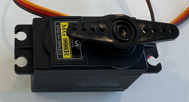
For this test, I temporarily replaced the SG90 micro servos with MG996R servos to check whether I could achieve a faster and stronger movement for the lever system of the project.
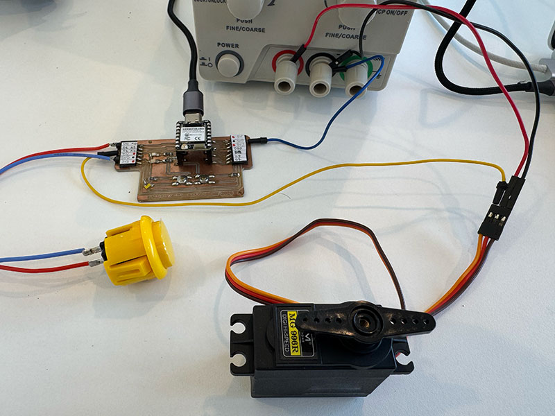
In addition to the buttons integrated into the PCB, I also added an external arcade button to test different interaction options and evaluate which one felt more comfortable and robust for the game.
The system was tested using a XIAO ESP32C6, as this will be the final microcontroller used in the definitive version of the PCB.
During the first tests, the servo worked correctly when powered directly from the 5V line of the PCB. Even so, I wanted to check whether an external power supply could improve the behaviour of the MG996R, especially because this type of servo requires much more current than an SG90.
For this reason, I carried out another test using an external 5V power supply connected directly to the servo. The connection was made by sharing the GND between the external power supply, the servo and the PCB/XIAO, while keeping only the control signal connected to the microcontroller.
However, during the tests I did not notice a significant improvement compared with powering it directly from the PCB. The servo worked correctly in both cases, and the movement speed and general response felt very similar.
This seems to indicate that, in this specific setup and working at 5V, the main limitation does not depend only on the power supply, but also on the characteristics of the MG996R itself, the mechanical load applied and the movement range used in the test. Although the MG996R provides much more torque than an SG90, it does not necessarily provide a much faster movement.
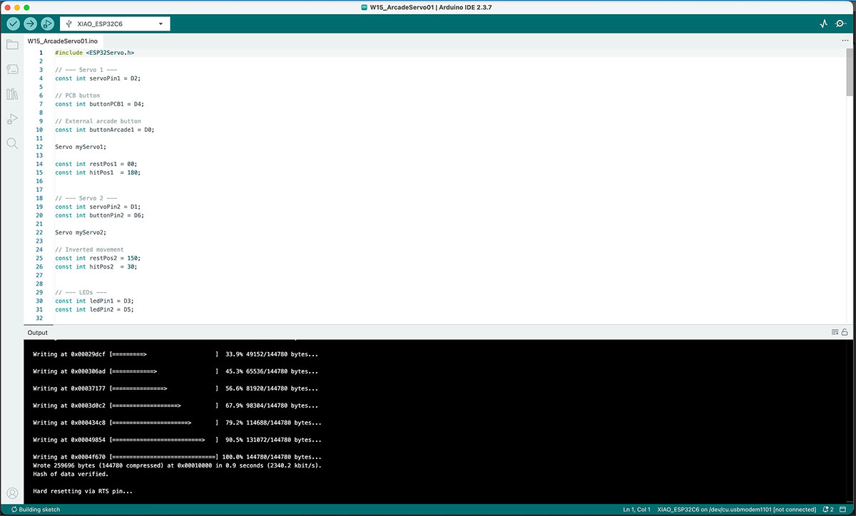
On the programming side, the code was adapted for the XIAO ESP32C6 using the ESP32Servo.h library. I also adjusted the movement angles and timing to reduce vibrations and mechanical bouncing at the ends of the movement.
Finally, servo 1 was configured so that it could be activated both from the button integrated into the PCB and from the external arcade button, allowing me to test both options at the same time.
Pin Connection
| Component | Pin | Connected to XIAO ESP32C6 | Function |
|---|---|---|---|
| MG996R Servo 1 | Signal | D2 | Servo control |
| MG996R Servo 1 | VCC | External 5V power supply | Power |
| MG996R Servo 1 | GND | Shared GND with PCB/XIAO | Ground reference |
| PCB Button 1 | Signal | D4 | Servo 1 trigger |
| External Arcade Button | Signal | D0 | Servo 1 trigger |
| LED 1 | Signal | D3 | Status indication |
| LED 2 | Signal | D5 | Status indication |
| Buttons | GND | GND | Ground connection |
Full time & High quality video available on my YouTube channel ↗️.
Arduino code W15_ArcadeServo01 Show code
Files for download
Week 16
Dates: 6/05/2026 - 12/05/2026
System integration
On holidays from 1st to 17th of May -Out off FabLab-
This is an excerpt from the documentation for the week 16 assignment. To complete this section, please visit Week 16 Assigment
User Experience Flow Diagram
I decided to represent it as an image (generated by AI)
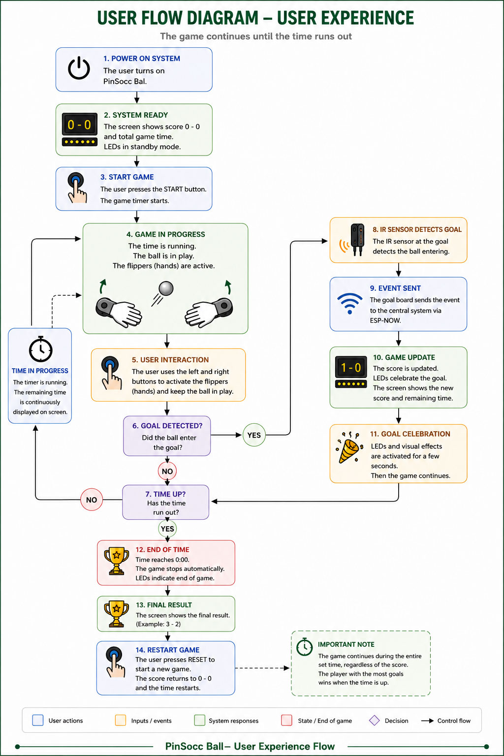
User Experience text Flow
PinSocc Ball is an interactive game inspired by pinball mechanics, where the match takes place during a fixed amount of time.
When the system is powered on, the main display shows the initial score and the total game time. Once the user presses the START button, the countdown begins and the game enters its active state.
During gameplay:
- the hand-shaped flippers remain active,
- players interact using physical buttons,
- the remaining time is continuously updated on the display,
- and the IR sensors monitor when the ball enters the goal areas.
When a goal is detected:
- the IR sensor detects the ball entering the goal,
- the event is transmitted to the central system using ESP-NOW,
- the score is updated,
- and visual LED effects are activated.
After the goal celebration animation, the game automatically continues as long as there is remaining time available.
The match does not end when a specific score is reached. The game continues until the timer reaches zero.
Once the time is over:
- the system stops the game,
- disables the flippers,
- shows the final result,
- and allows the user to start a new match using the RESET button.
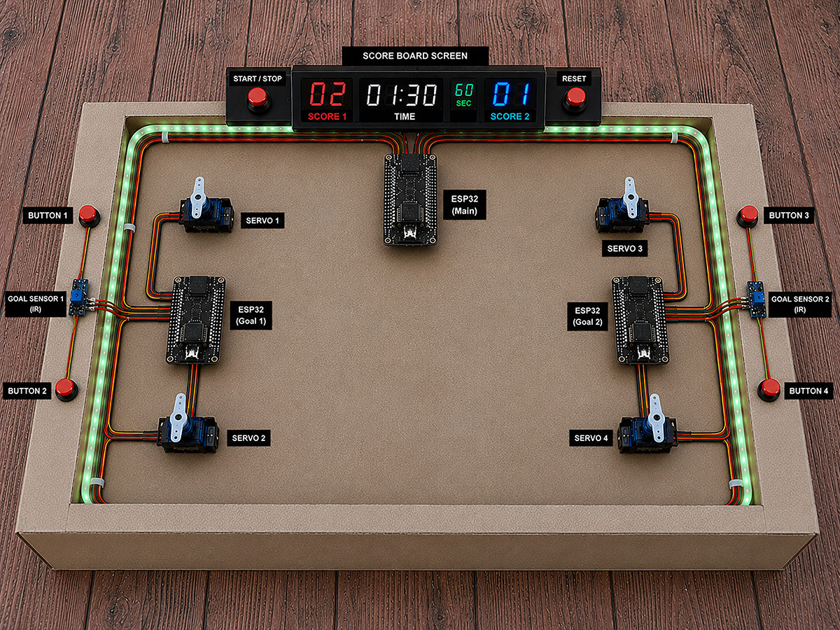
Project system diagram
One of the most important parts of developing PinSocc Ball is integrating all the electronic and mechanical systems that allow the project to work as a single interactive experience.
Although from the outside the game feels simple and fluid, internally it is based on a distributed architecture where different boards, sensors, actuators, and visual output devices work together in real time.
To organize this communication, the project is divided into several subsystems connected through ESP-NOW. Each goal has its own ESP32 board, which reads the local buttons and IR sensor, while also controlling the servos that move the hand-shaped flippers.
At the same time, the central system manages the overall game state, updates the score, controls the LED lighting, and keeps the whole experience synchronized during the match.
The following diagram shows the general architecture of the project, including how the electronic modules, power distribution, and wireless communication are integrated inside PinSocc Ball.
ChatGPT user Experience Flow Diagram Prompt Show prompt
Integration of the elements
Creating the cardboard model has allowed me to consider, on a physical scale, how to integrate the elements, as well as the overall dimensions.
ChatGPT Skeetch over carboard model Prompt Show prompt
Week 17
Dates: 13/05/2026 - 19/05/2026
On holidays from 1st to 17th of May -Out off FabLab-
Week 18
Dates: 20/05/2026 - 26/05/2026
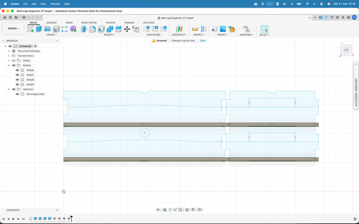
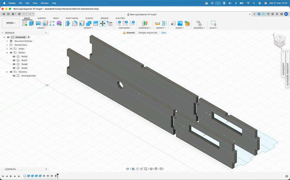
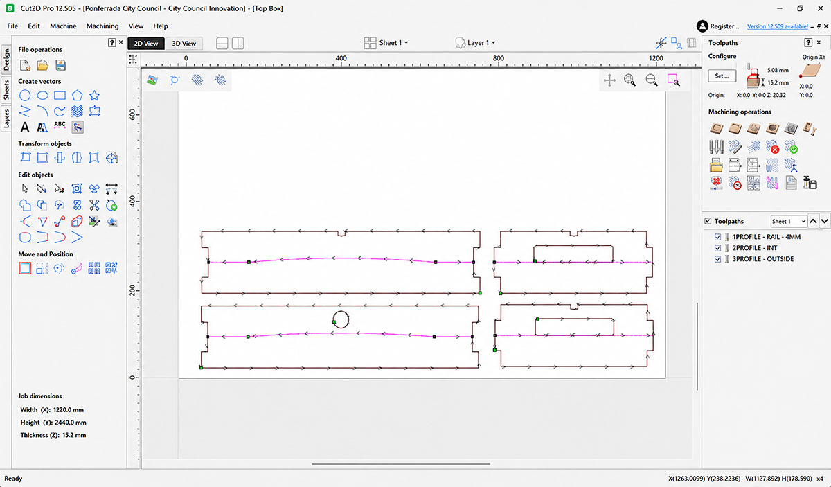
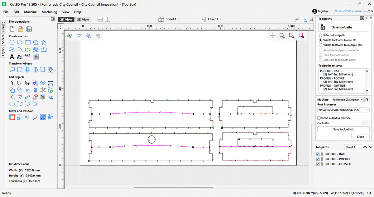
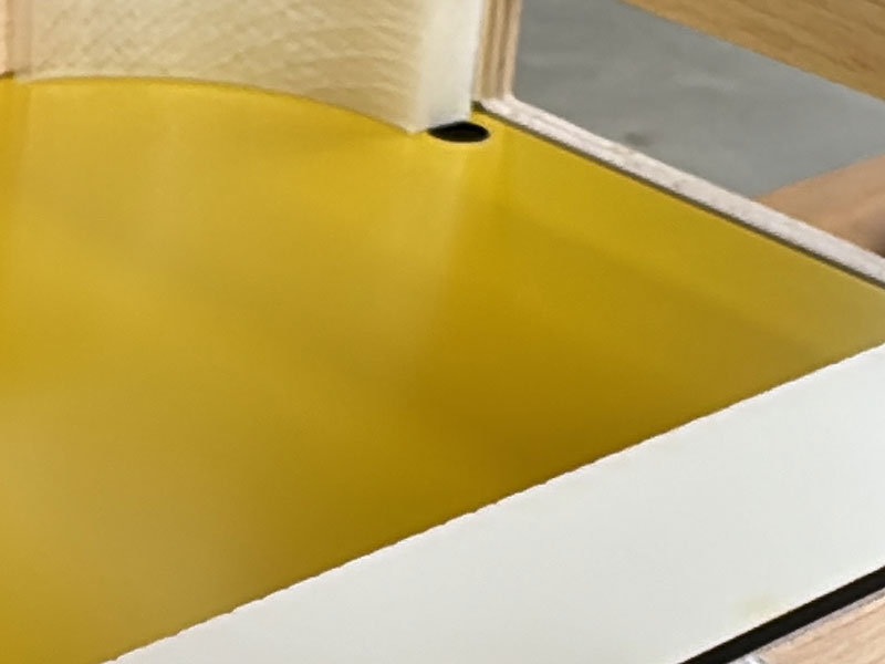
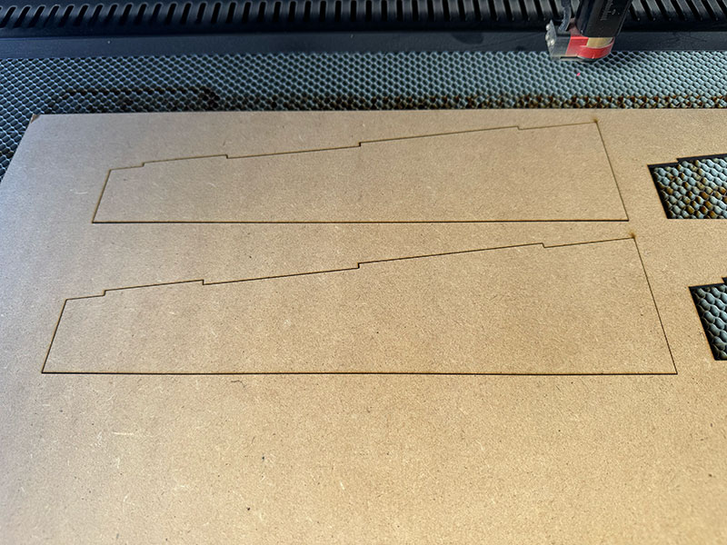
Specifically, I designed one of the side pieces with a longitudinal groove that is 4 mm deep and 4 mm wide, matching the diameter of the milling bit used. The idea is to fit the two-layer acrylic into this groove, as it will be used as the base of the playing field.
The goal of this design is to create a slight slope from the center towards both goals. This should help the ball naturally move towards one of the goals and make the game more dynamic and fluid.
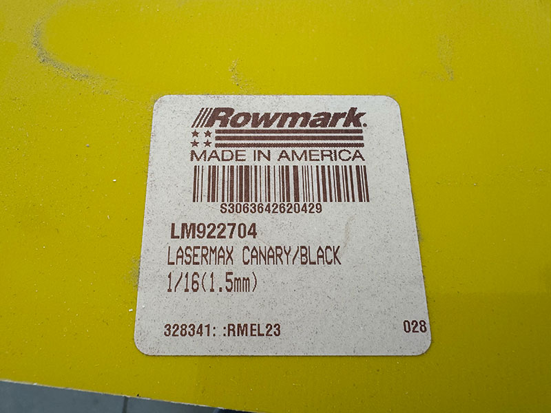
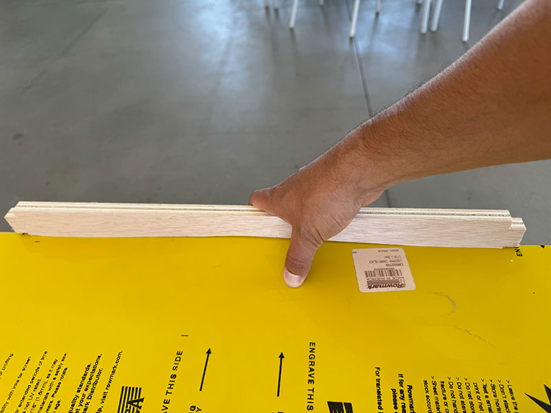
To check if the material was suitable, I made a first test using one of the two-layer acrylic sheets (1/16" engraving plastic) available in the Fab Lab, specifically the 1/16” Canary/Black acrylic.
The test was positive, as I was able to confirm that the material bends properly without any problems. This also gives me the possibility of making the channel with an even narrower milling bit in future versions.
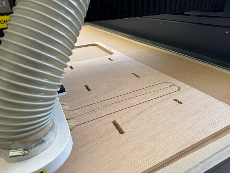
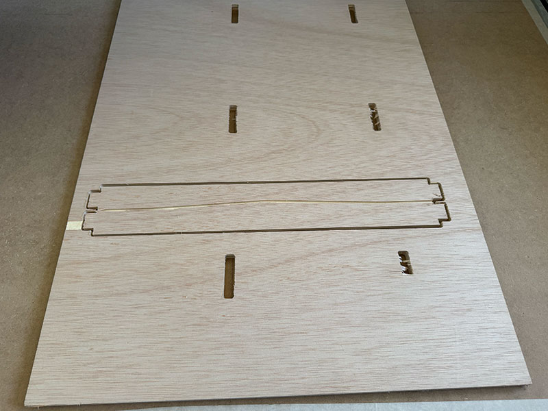
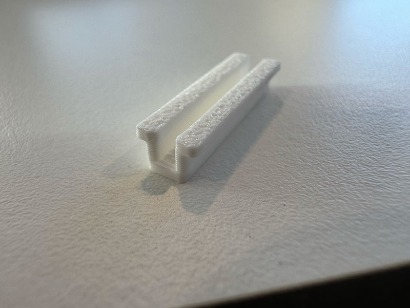
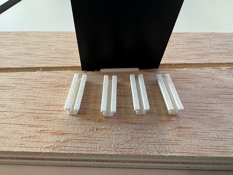
Although the longitudinal groove is 4mm wide and the two-layer is 1.5mm wide, making the material easy to mold, I've designed some 3D-printed pieces to make the fit more precise, which I'll place where needed.
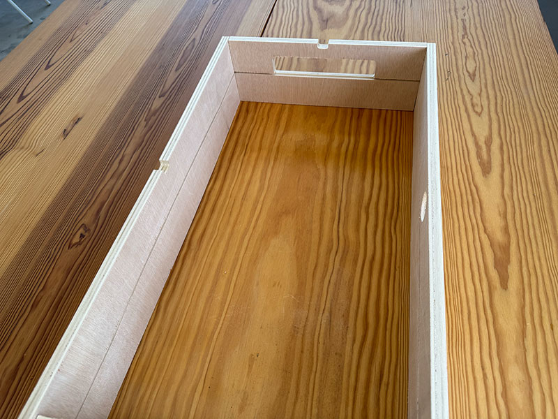
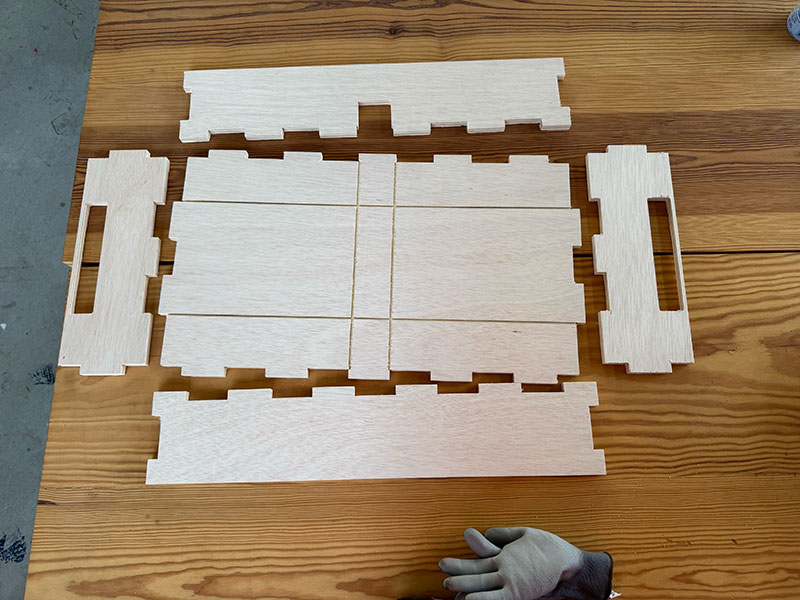
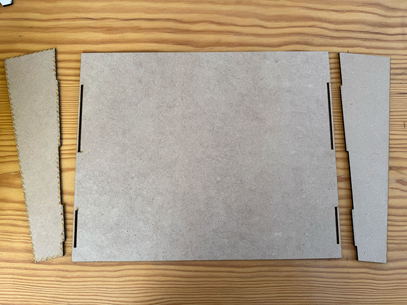
Once the fit test was completed, we moved on to designing the top part of the box, which includes the playing surface.
High quality video available on my YouTube channel ↗️.
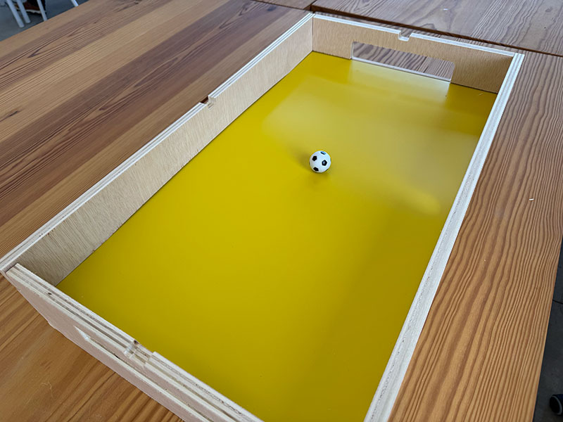
Now that I have all four pieces for the top part, I'll proceed to assemble them.
Using the laser cutter, I make a two-layer piece of the required size and insert it.
Files for download
- CNC soccer field Test (W14CNCsoccerTest.dxf) DXF · 8 Kb
- CNC soccer field Test (W14CNCsoccerTest.crv) CRV · 228 Kb
- CNC soccer field Test (W14CNCsoccerTest.nc) NC · 82 Kb
- Longitudinal groove fit (Railway.stl) STL · 2 Kb
- UpperCase (UpperCase.f3d) F3D · 151 Kb
- UpperCase (UpperCase.svg) SVG · 6 Kb
Week 19
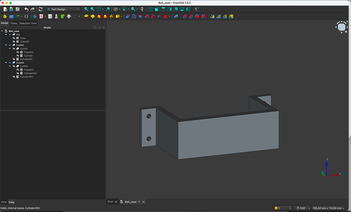
During this week I continued integrating all the different elements of the project. One of the first tasks was designing the lower box, which will contain the ball return system every time a goal is scored.
The idea is that, from each goal and outside the upper box, a 3D-printed part will connect both boxes together. This component will guide the ball from the goal area to the beginning of the return system located inside the lower box.
Once the lower box was assembled, I started designing the ramps that will form the ball return system. My initial idea was to manufacture them using 3 mm MDF with a press-fit construction, but at this point I decided to pause this development. I considered it more important to focus first on making the upper part of the game fully functional and leave the return mechanism for another design spiral.
With that decision made, I moved on to one of the most important parts of the project: the electronics.
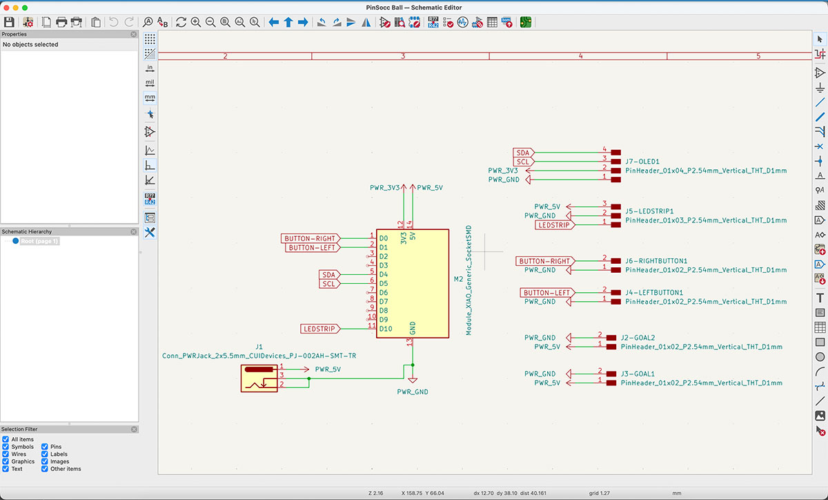
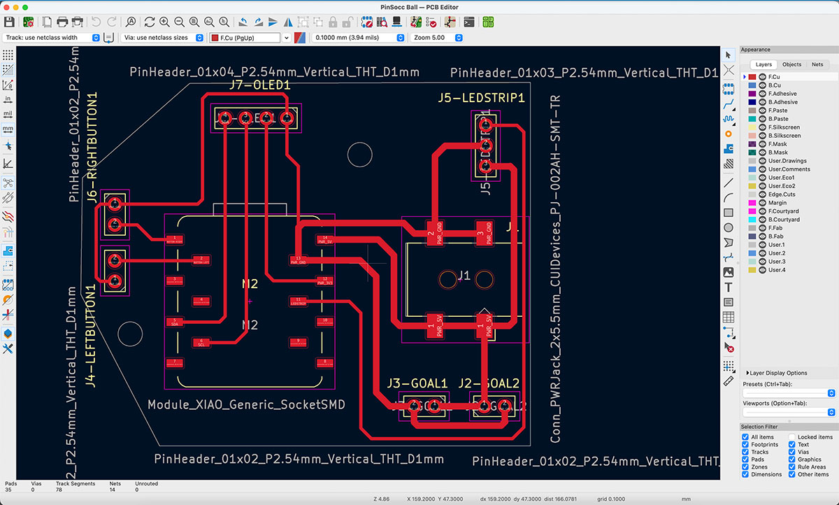
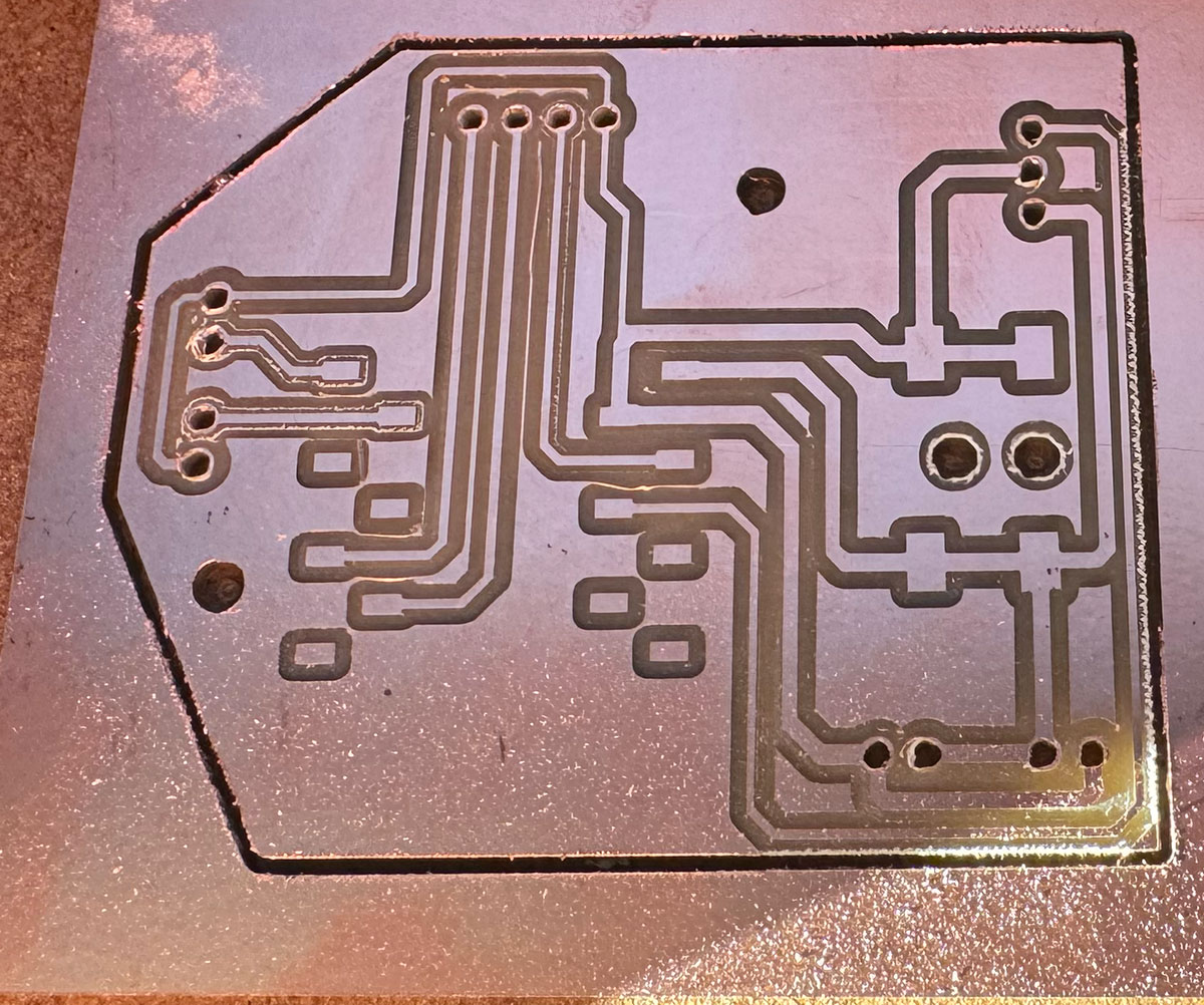
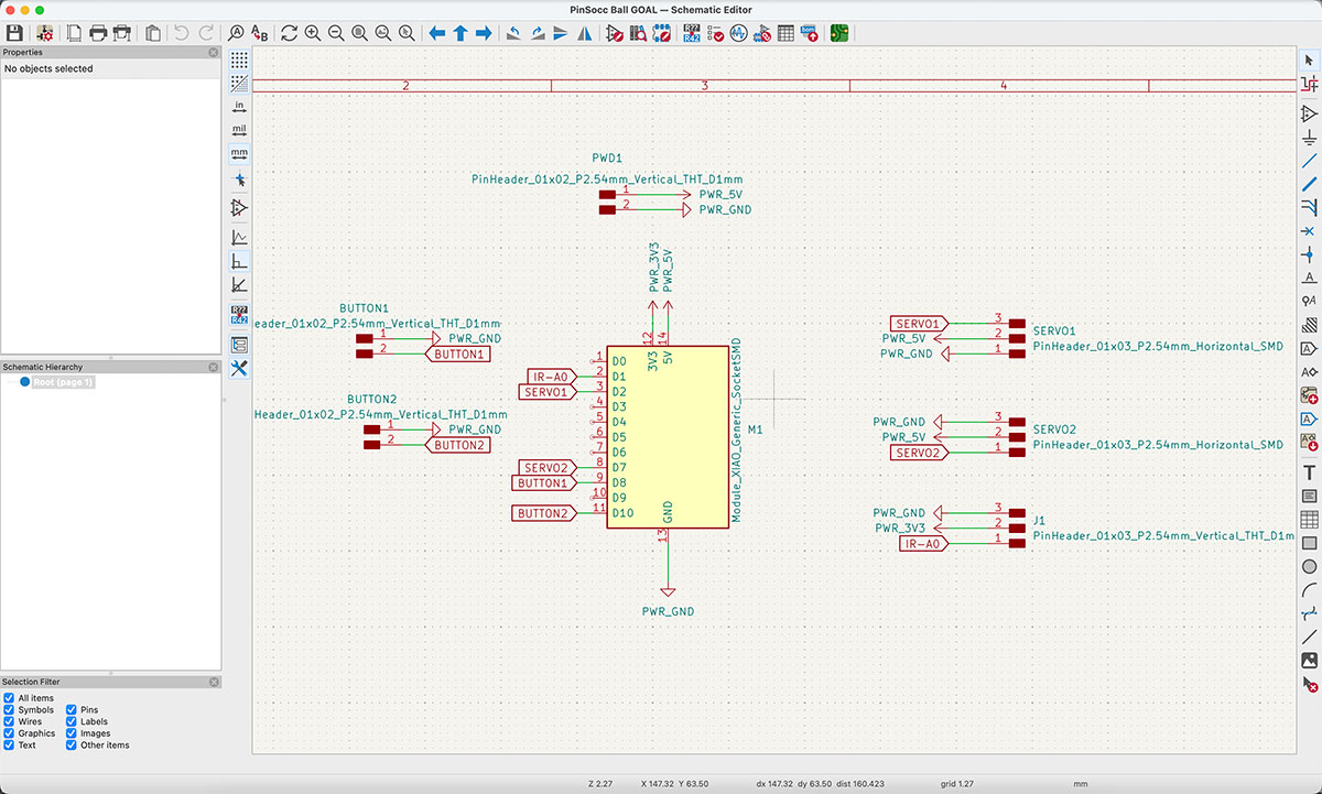
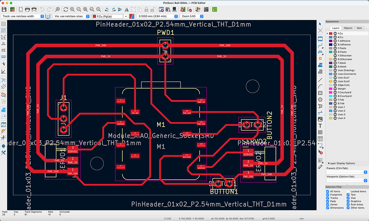
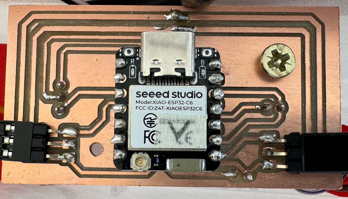
I designed a total of three PCBs: one main board responsible for coordinating the entire game and two secondary boards, one for each goal.
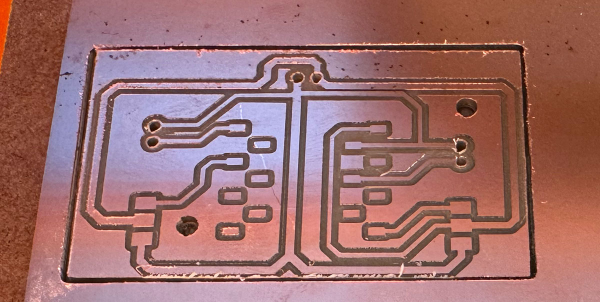
Following the same workflow used during Week 8, Electronics Production, I designed the schematics and PCB layouts in KiCad and then fabricated the boards using FR1 material and the Roland SRM-20 milling machine.
Main PCB
Goal PCB (2 units)
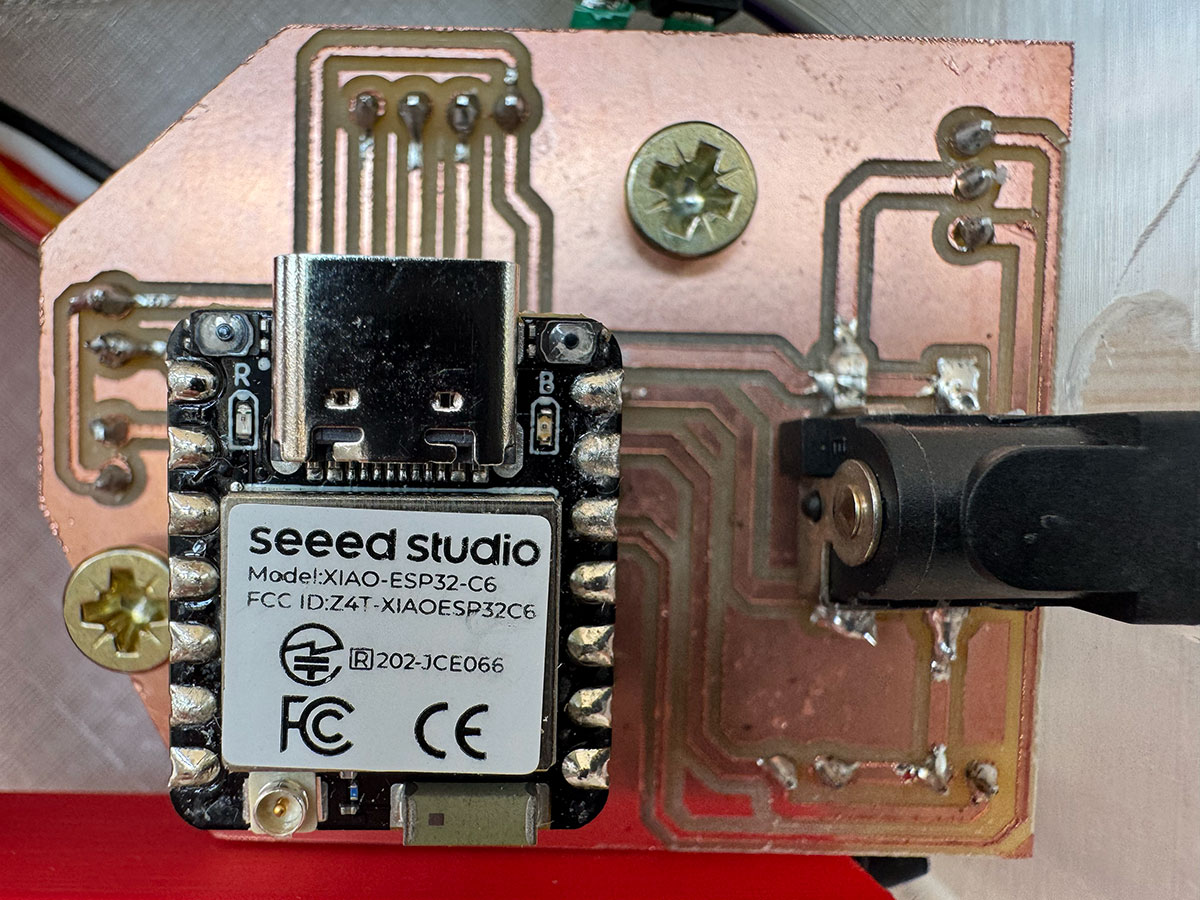
Soldering the Electronics
This stage turned out to be one of the biggest challenges of the entire project. Soldering is definitely not one of my strongest skills, and I encountered several issues along the way.
In fact, I had to remake some of the PCBs because while soldering components I accidentally created shorts between traces that I was unable to repair.
Fortunately, with patience and a lot of careful inspection, I eventually managed to solder all three boards and get them working 100% reliably.
With the electronics mostly completed, I shifted my attention back to the upper playfield.
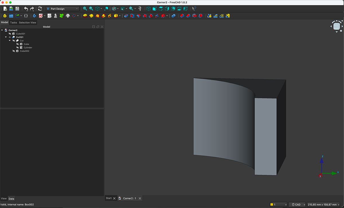
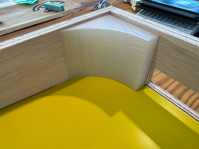
One aspect I wanted to improve was the behavior of the ball when it reached the corners of the field. To solve this, I designed rounded corner pieces that help redirect the ball back towards the hand flippers instead of letting it get trapped.
These parts were designed and printed using transparent filament. Besides their mechanical function, I thought they could create interesting lighting effects since the LED strip runs around the entire perimeter and passes directly above all four corners.
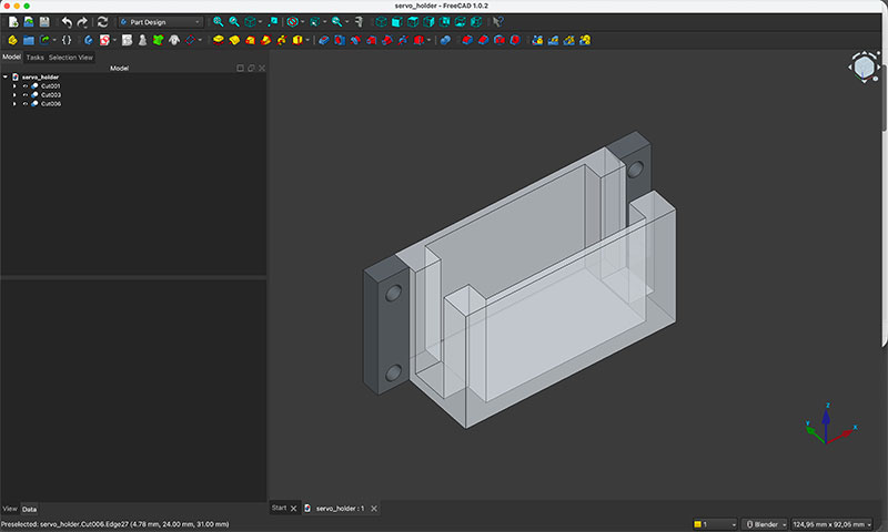
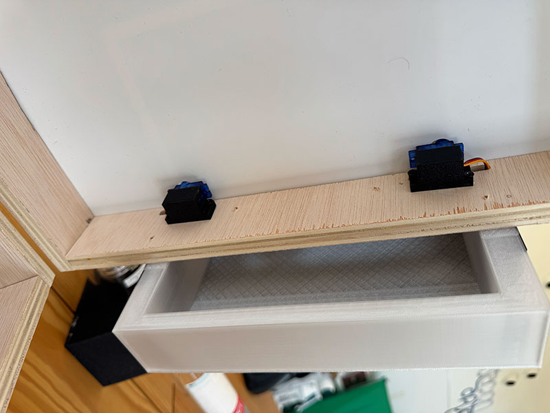
The previous week I had laser-cut the two-layer playfield panel. At this point I needed to determine the exact servo positions and mounting holes.
To do this, I first designed and printed a dedicated servo holder that allows the servos to be mounted securely onto the structure. After testing the positioning and taking precise measurements, I reused the already-cut playfield and brought it back to the laser cutter to create only the required holes.
This allowed me to save material while validating the dimensions before producing the final version. After reassembling everything and confirming the measurements, I was ready to manufacture the definitive playfield in its final color.
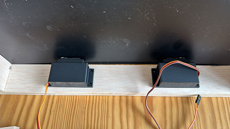
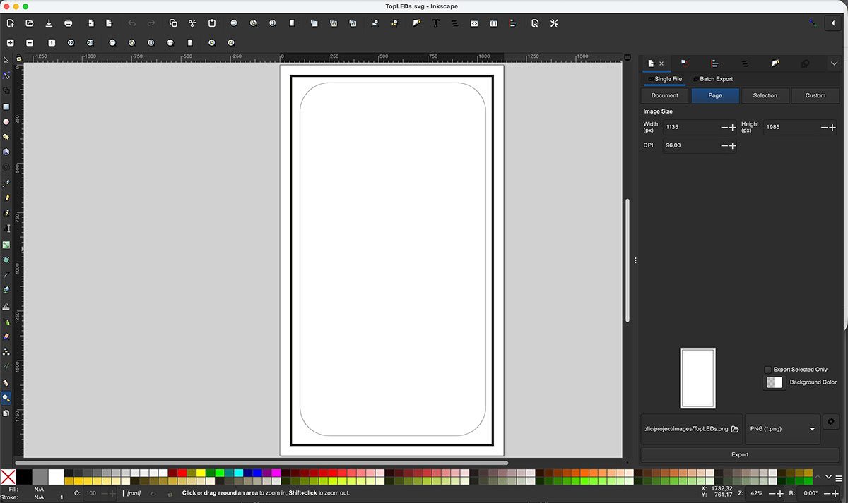
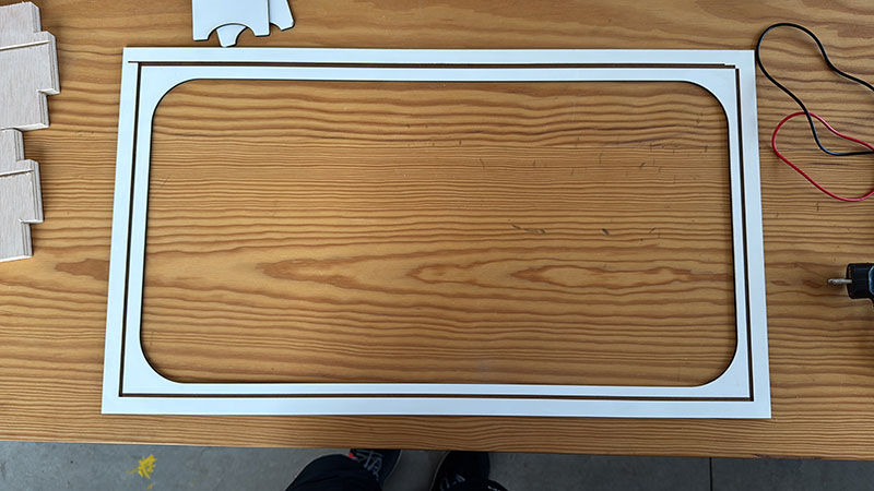
The next step was designing the top cover. This component serves two purposes: housing the perimeter LED strip and hiding the power cables running from the main PCB to the goal PCBs.
Although there was enough room underneath the playfield to route these cables, I felt that the upper solution was cleaner and easier to implement. It also avoided machining channels in the wooden structure and eliminated any possibility of interfering with the ball movement.
The cover was manufactured from 3 mm white-coated MDF and cut using the laser cutter. I also engraved a small guide channel so the cable could be glued perfectly straight during assembly.
While working on other parts of the project, I eventually returned to the design of the ball return ramps for the lower box.
These ramps, also made from 3 mm MDF, are responsible for guiding the ball from the goal area to the exit point where it can be manually reintroduced into the game.
Their design directly affects the goal-side modules because these components must simultaneously house the local PCB, contain the player buttons, detect the ball passing through the goal and guide it toward the return mechanism below.
To understand it better, this video
As the final part of the return system, I also designed a 3D-printed component that acts as a waiting area where the ball rests before being put back into play.
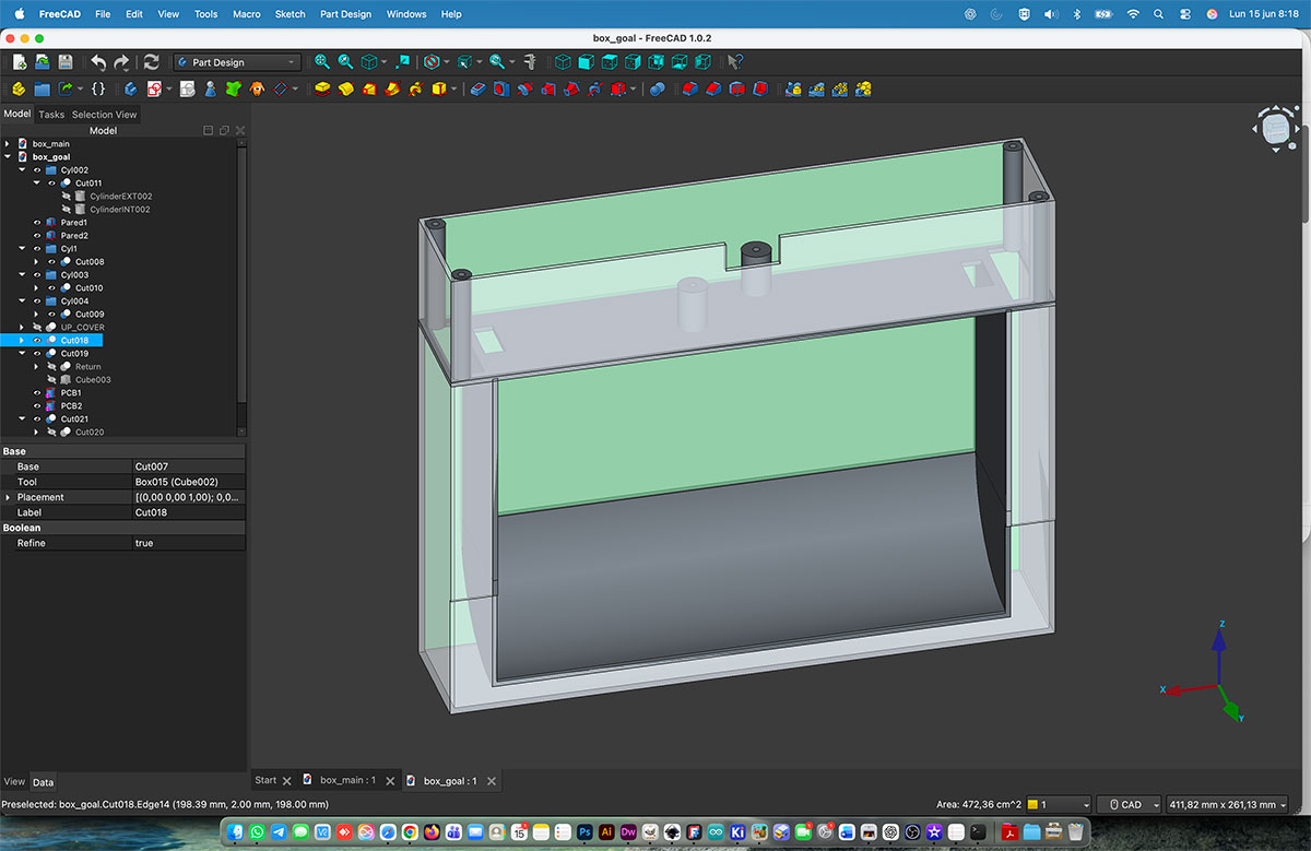
Week 20
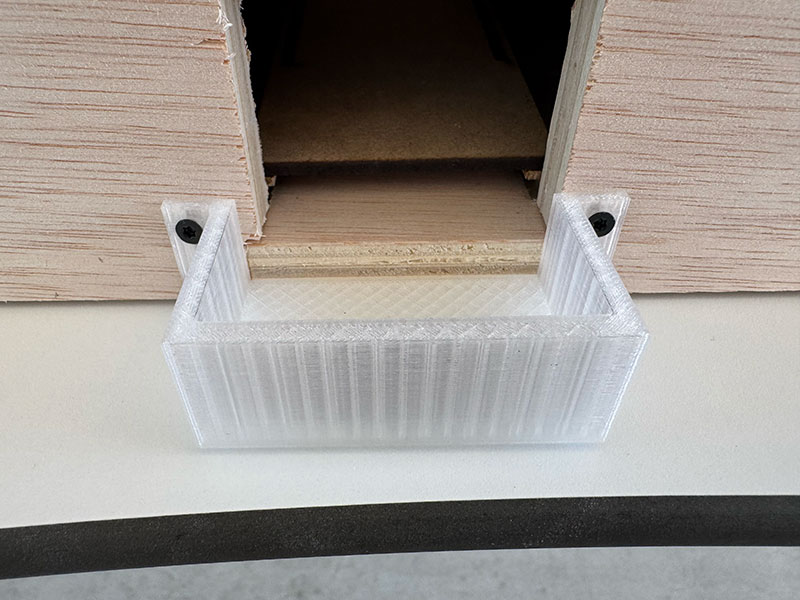
This week started with the design of one of the most important printed parts of the project: the component that connects the upper game box with the lower ball return box.
This part performs multiple functions. Besides allowing the ball to travel between both boxes, it houses the infrared sensor used to detect goals, contains the local PCB and integrates the player control buttons.
During the design process I also had to consider cable routing. Enough internal space was required to route the servo wires up to the PCB as well as the wiring for the infrared goal sensor.
Because of its size, this component introduced an additional manufacturing constraint. I had to design it while considering the maximum build volume of the largest printer available in the Fab Lab, the Bambu Lab X1 Carbon, which offers a print area of approximately 25 cm in each axis.
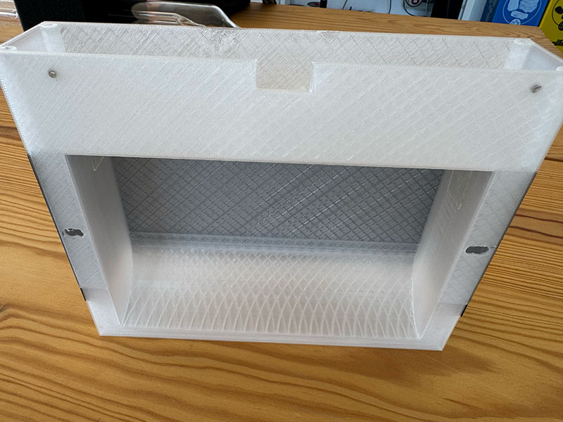
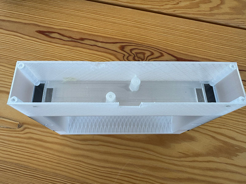
Once the design was completed, I scheduled the prints overnight. Each part requires around ten hours to print, so using nighttime printing maximized machine availability during the day for other Fab Lab activities.
Since I needed two units, I also used the opportunity to compare different aesthetic options. One version was printed using transparent filament and the other using black filament so I could evaluate which one integrated better into the final project.
While the prints were running, I continued developing other parts of the system.
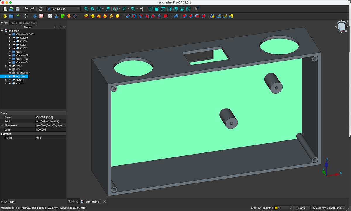
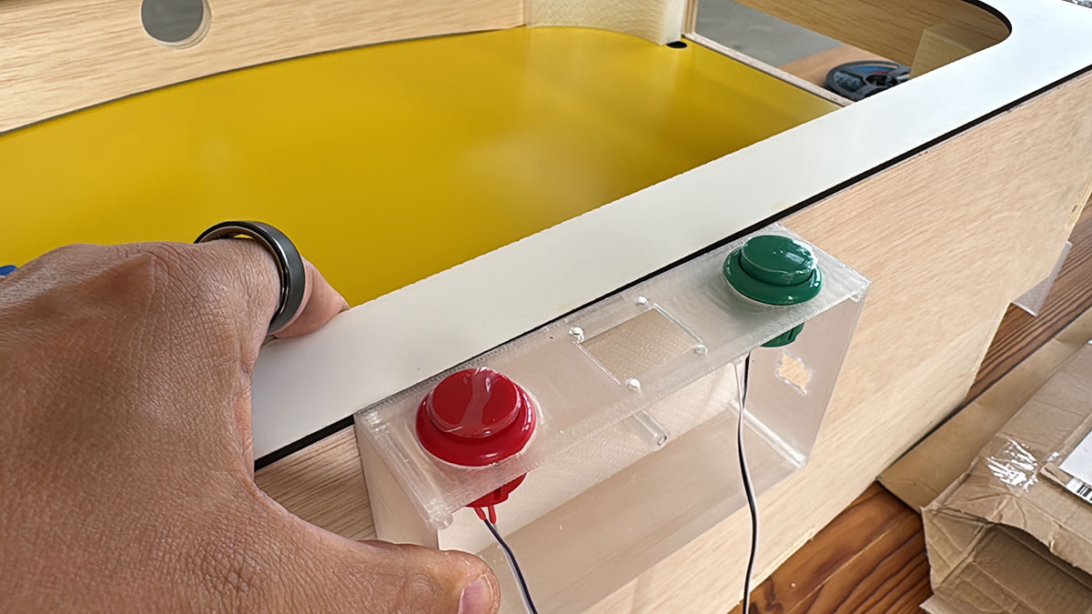
I designed the enclosure that will house the main PCB, the OLED display and the game start and reset buttons.
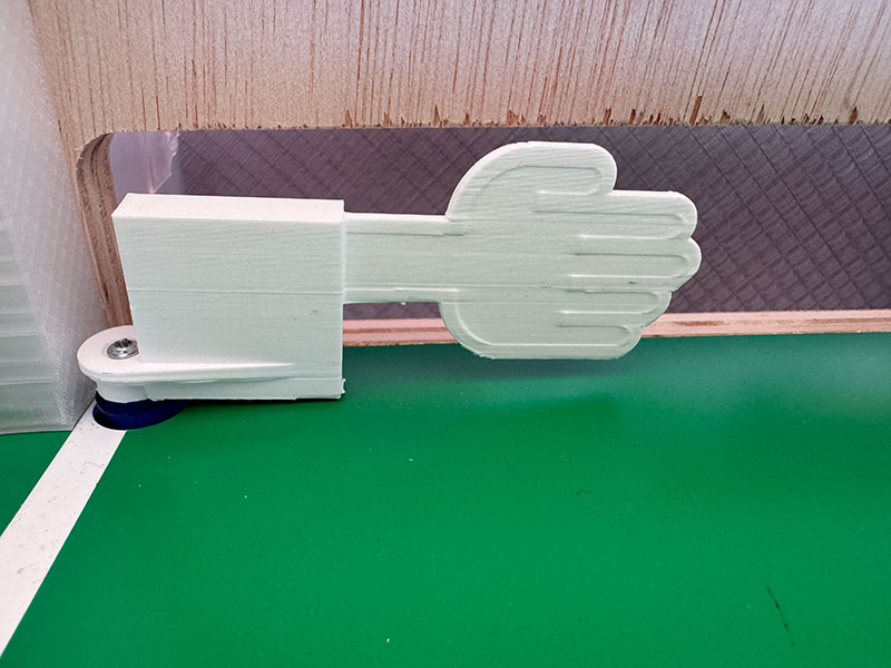
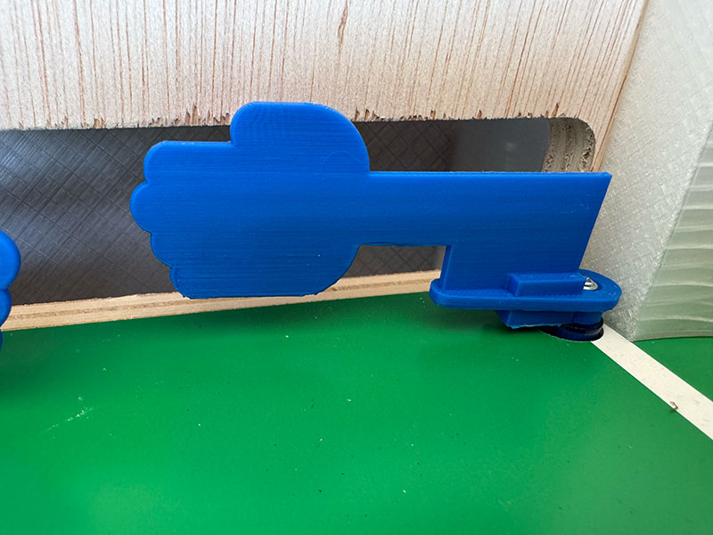
I also updated the hand flipper design originally created during Week 3. The main modification was adapting the connection geometry to match the final servo model selected for the project, ensuring proper integration with the servo horn. I also took the opportunity to make a reinforced version for testing (the white one).
With all the components manufactured and ready, I finally started the full assembly process.
Programming and System Integration
Another important part of the development process was programming the three XIAO ESP32-C6 boards that control the different subsystems of the game.
Following the architecture defined in the User Experience Flow Diagram, I developed the Arduino code for each board according to its specific role within the system. The main PCB is responsible for coordinating the game logic, score management, OLED display updates, lighting effects and communication with the goal boards. Meanwhile, each goal PCB manages the local inputs and outputs, including the hand flippers, goal detection sensors and player buttons.
The implementation required programming the communication between boards, defining the different game states, handling user interactions and synchronizing events across the entire system. Throughout this process, I performed multiple tests and iterations to ensure reliable operation and a responsive gameplay experience.
This software development stage was fundamental to transforming a collection of independent components into a fully integrated and functional game system.
At this stage, electronics, mechanics, digital fabrication and programming finally came together into a single working system, making this one of the most significant integration milestones of the entire project. Seeing all the individual elements interact correctly for the first time was a major step forward and confirmed that the overall design decisions made throughout the development process were working as intended.
Since this phase is especially valuable for anyone interested in replicating the project, I decided to document the complete assembly process in the final project page, where it will serve as a step-by-step guide for future builders.