WEEK 07
Computer-Controlled Machining
How the week started
I was intrigued to start this week as this was something I wanted to try out for a long time, to make something out of wood or plywood. Though my agenda was to design a laptop stand which could be moved around with ease and rotated. I didn’t make it cause it would need other components to do it and I wasn’t ready to design within a short period of time. So that is gonna continue as my dream project.
How the week ended
This week was hectic, I spent a lot of time designing, editing, redrawing, despite burning the midnight oil, I am somewhat unhappy with my workflow. the fun part of the week was being taught about CNC machines, materials, workflow by, Mufeed Mohamed and Revisankar S . I did a mistake of forgetting to turn on the exhaust of the laser cutting machine and it started to fume up immediately. I stopped the machine immediately.
Week 07’s Assignment
Group assignment:
- Complete your lab’s safety training.
- Test runout, alignment, fixturing, speeds, feeds, materials, and toolpaths for your machine.
- Document your work on the group work page and reflect on your individual page what you learned.
Individual project:
- Make (design + mill + assemble) something big.
Workflow
CAD (Fusion) → Scaled Model Test by Laser Cut → Assemble Model
↓
CAM (Set Tool Path) → Cut → Sand → Assemble Model
Brainstroming designs
Initially I wanted to design something for my cats, a kerf bend cat perch. Something that could be removed and disassembled with ease. Then I stuck to a simple shape without any kerf bends. As I started to design in unfamiliar software Fusion, we were shared a few Fusion tutorial videos (1, 2, 3) so we could get a better hold of the software. It definitely helped me a lot. I chose another project that felt simple initially.
Brain stroming
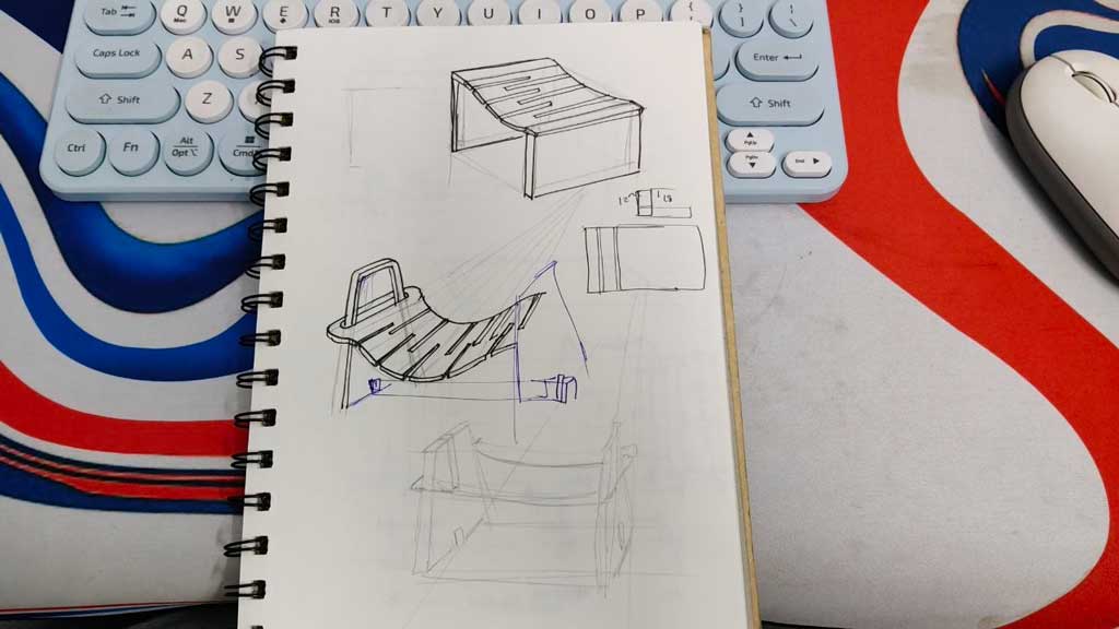
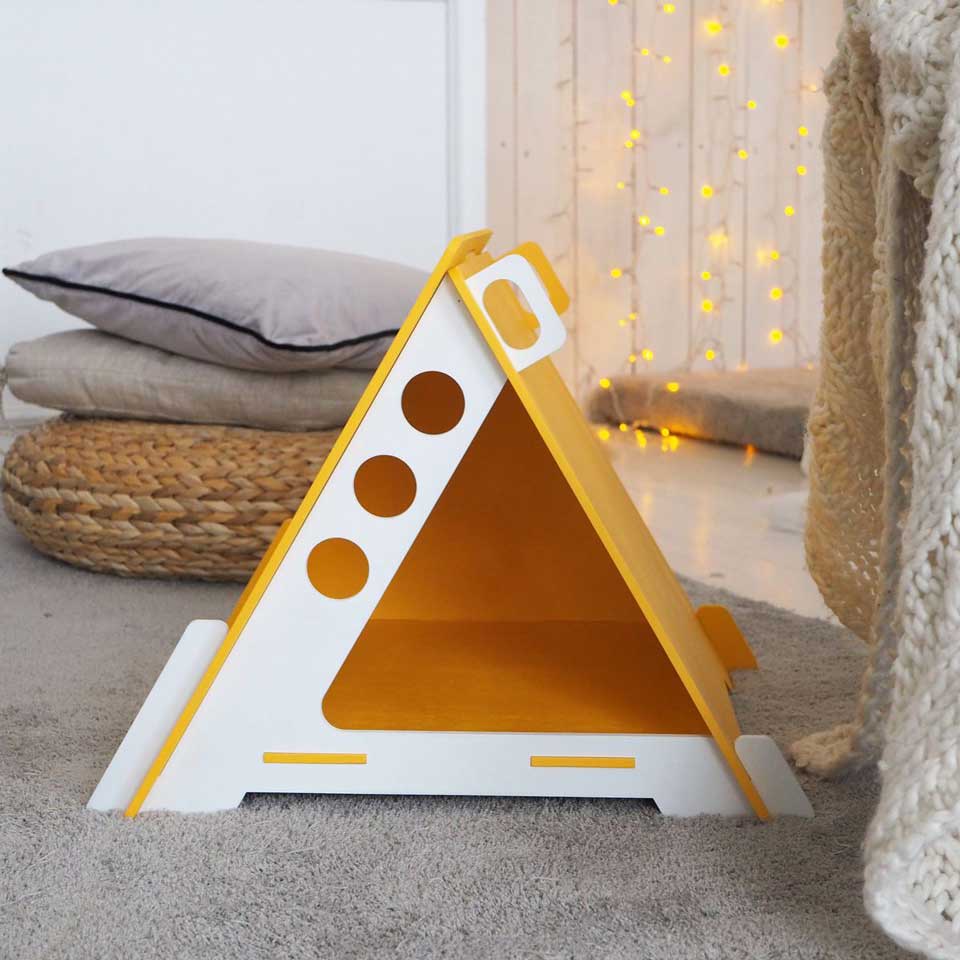
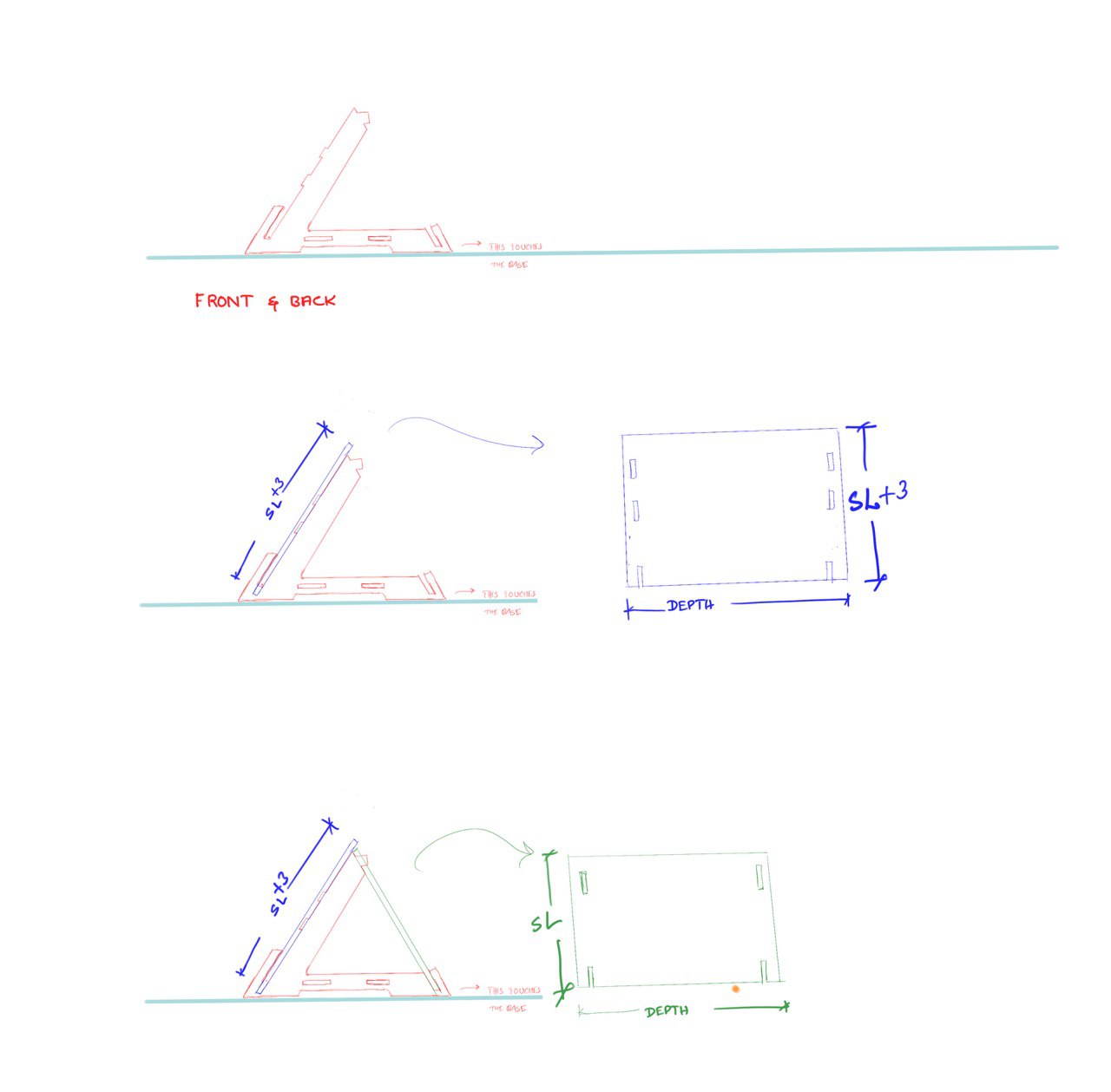
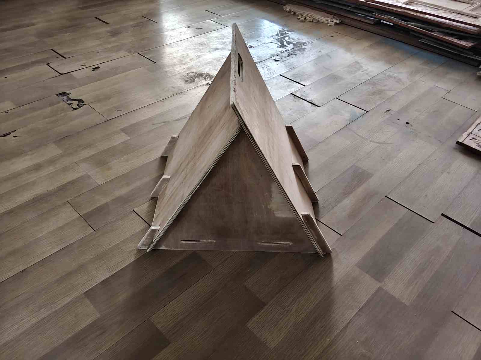
I settled down to a triangular cat house, inspired from a Pinterest search. The design looked simple. I came across issues with the model. Finding the order in assembling the model, angle to cut the slot in what a pocket hole is, because the slots didn't go in otherwise.
Fusion - troubled waters
The unfamiliarity with Fusion continued this week, yet got a better hold of it than the last time I used it.
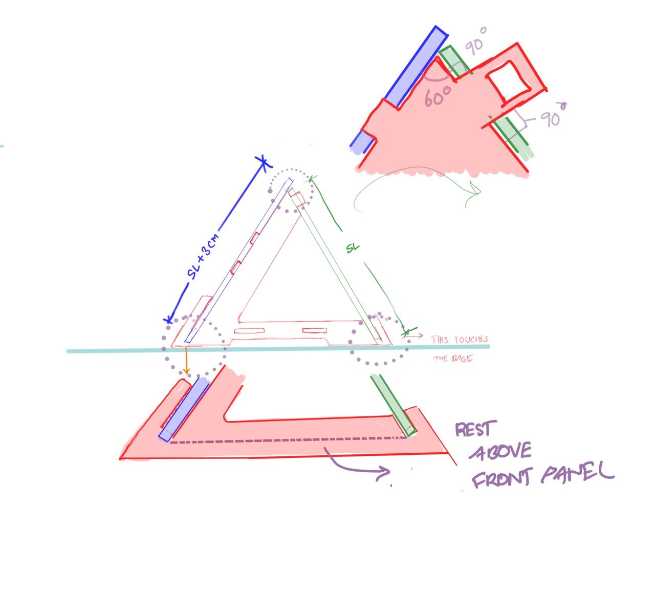
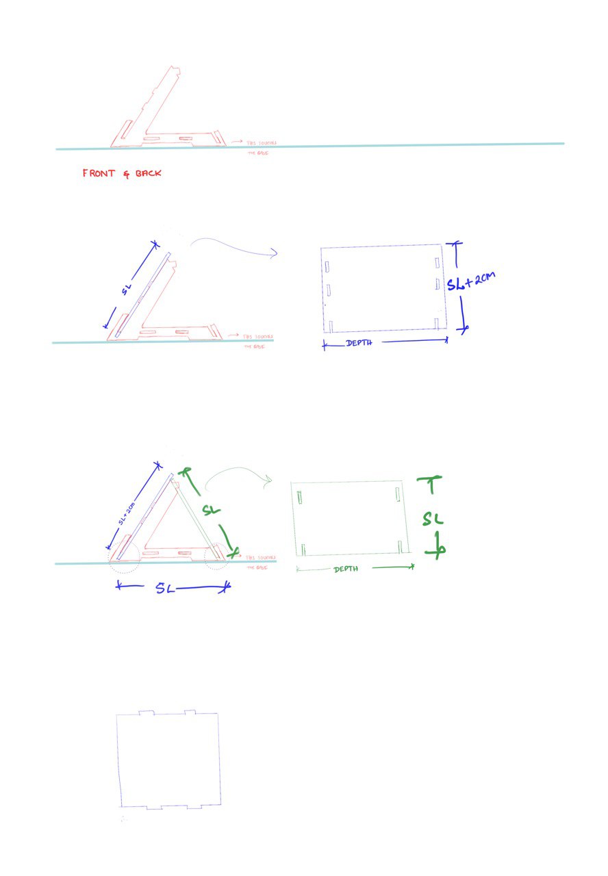
Layout setup
.jpg)
.jpg)
While drawing the model, I chose the front plane and constructed an equilateral triangle so that all the sides would be equal. I then offset the equilateral triangle to the plywood thickness.
Front panel design
.jpg)
.jpg)
.jpg)
.jpg)
.jpg)
Setting parameters for the thickness helps in adjusting the model to suit the stock we use. In our case, we used 12 mm plywood.
An error to remember
Red Flag: The mistake I made here was linking all my values to plythickness. I thought that by doing so the whole model would automatically adjust, but when I completed the model and applied the parametric change it affected the model a lot. Some constraints were missing and the geometry shifted.
From this I learned to use the parametric value only for plythickness and not for other measurements. If needed, I can create another parameter with the same value but give it a different name.
.jpg)
Here I extruted the area using plythickness. this was unnecessary , I could have done with a defined value.
.jpg)
I added the side panels. I initially took a more complex approach to draw this. I extruded from the slot in the front panel and then extruded it sideways to create the side panel. After that, I had to combine the bodies.
This could have been done in a simpler way by extruding directly from the first sketch. In the dialog box, set the Extend Type to "To Object". It is also better to change the Operation to "New Body" most of the time; otherwise, the body may automatically join with a nearby body, which we do not want.
.jpg)
This could have been done in a simpler way by extruding directly from the first sketch and then using Modify → Combine → Join.
Perforation
This is one step I am glad that I learned. When two objects are connected by a slot, we first select the blue body. This is the body that needs to be perforated.
Go to Modify → Combine. Select the target body (the body to be perforated), and then select the tool body. There can be more than one tool body.
Remember to check "Keep Tools" so that the tool body remains even after the cutting operation.
Perforation setup
This is one step I am glad that I learned. When two objects are connected by a slot, we first select the blue body. This is the body that needs to be perforated.
.jpg)
.jpg)
.jpg)
.jpg)
.jpg)
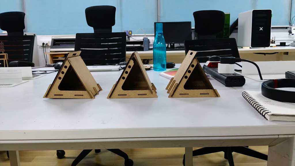
Scaled Model Testing
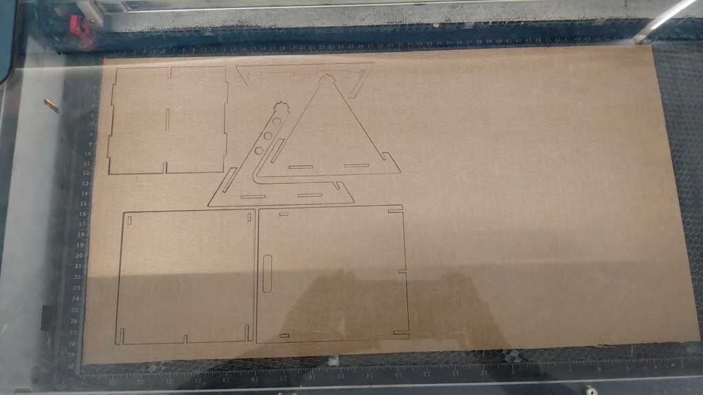
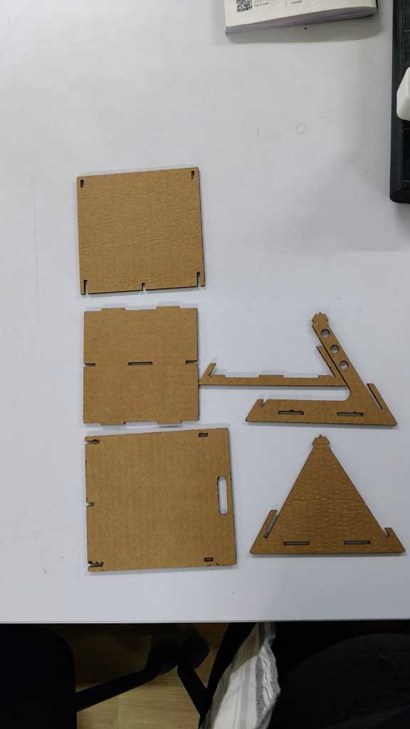
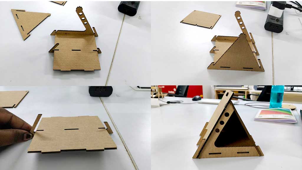
I would say this step is crucial when you are designing something for the first time. This helps to understand how to fix the model and what difficulties I might face.
The model is cut in cardboard using the Trotec Speedy 100 laser cutter Learn More
Nifty Dogbone
Download the Nifty Dogbone tool from Autodesk Marketplace Download
A dogbone is applied, otherwise the 6mm bit would leave a curved corner inside at the right angle connections. This would make it difficult to connect or join the pieces. Dogbone allows the tool to cut into the inside right angle joints.
.jpg)
.jpg)
.jpg)
.jpg)
.jpg)
.jpg)
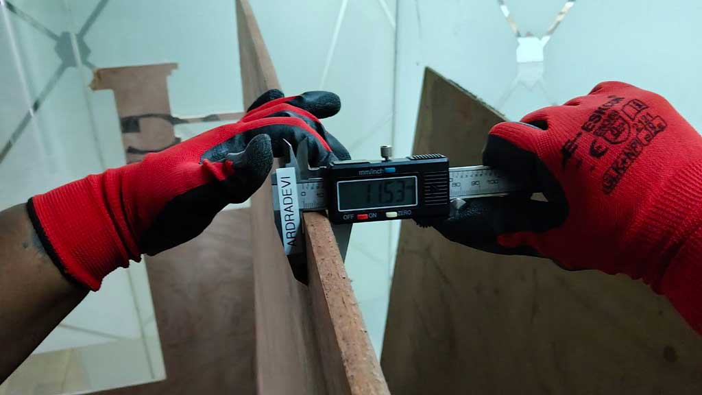
Preparing the File for CNC Routing
The plywood I used was not exactly 12 mm, but 11.3 mm. As I had mentioned earlier, I did not use the parametrics correctly, so I had to scale the model using a scale factor of 1.04634.
.jpg)
.jpg)
.jpg)
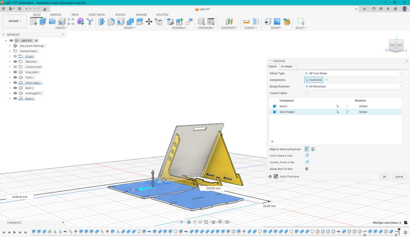
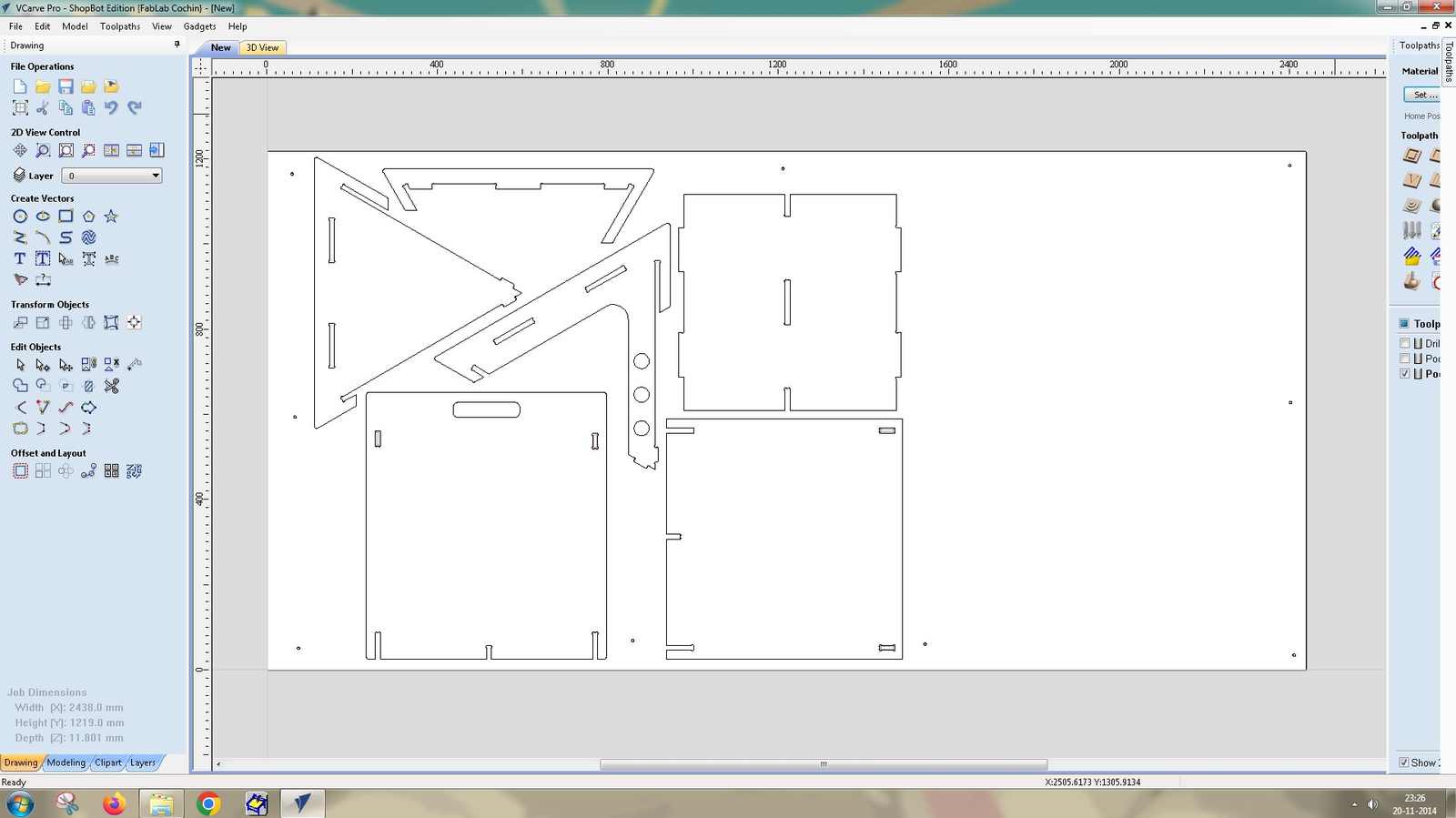
Using the Arrange tool is crucial because the pockets need to be machined on the inner side of the panels. The correct face must be selected as the top face before arranging the parts on the sheet. The envelope was set to 8 ft × 4 ft, which matches the dimensions of the plywood sheet being used.
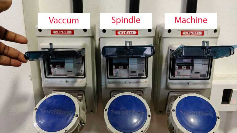
Safety Measures
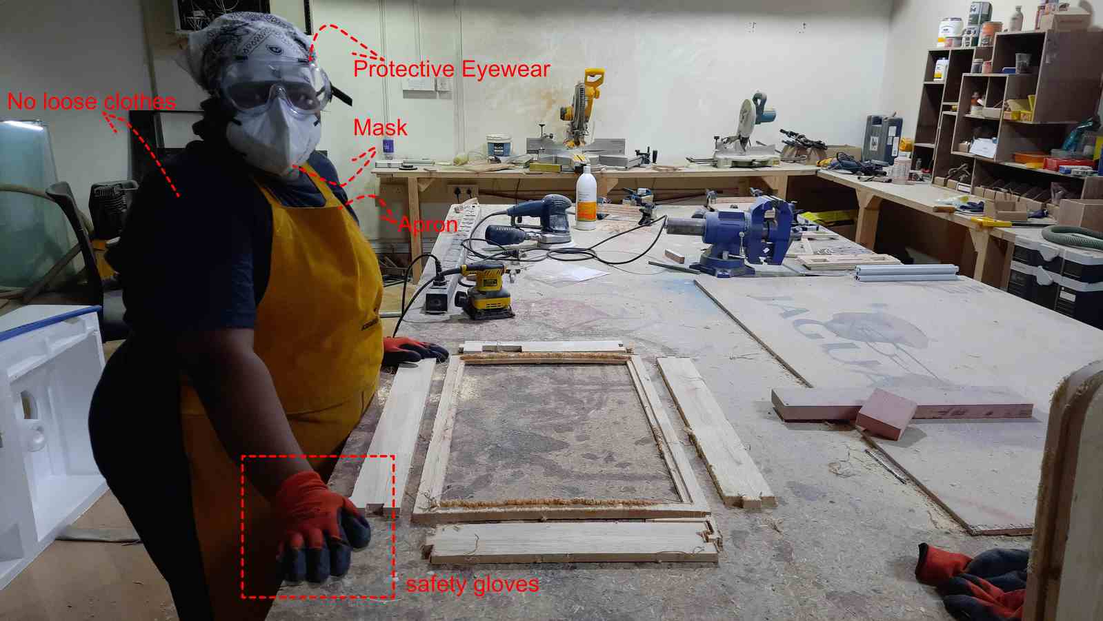
- Before stepping foot into the woodworking area or operating the ShopBot, the safety measures mentioned in the image and the use of safety shoes are mandatory.
- No loose attire, as the spindle rotates at high speed and might cause accidents, among other possible ways things could go wrong.
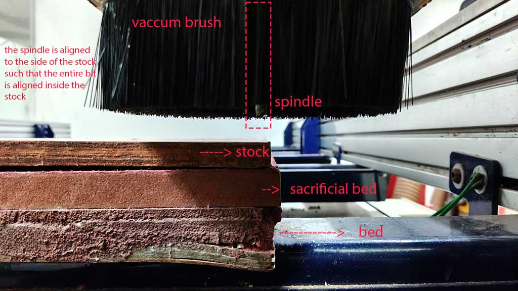
- While near the machine, maintain distance when setting the axes.
- Ear protective gear is important, as the CNC machine and the vacuuming process can produce loud noise.
- Do not leave the machine unattended or use your phone mindlessly.
- In case of any emergency, slam the red button to stop the machine.
- Operate the machine with utmost care.
Also, this photo was taken during my final project's sanding stage. Since time travel is not known to me yet, I could not go back and remind myself to take a safety photo during the CNC operation.
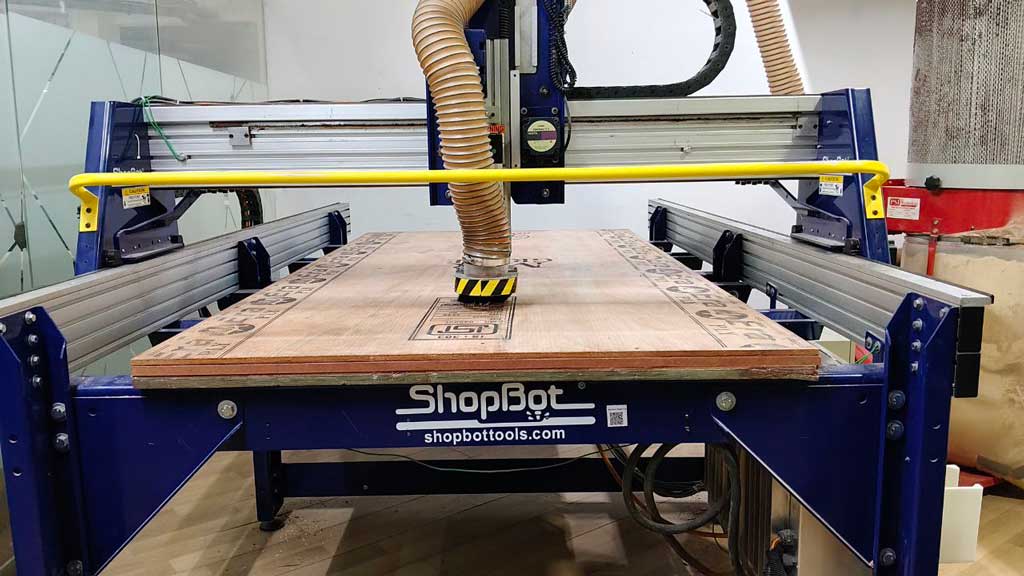
ShopBot PRS5 Alpha
Model: PRS5 Alpha 4’x 8’ with 2.2hp HSD Spindle
The ShopBot PRS5 Alpha is a 3 axis CNC router with movement along the X, Y, and Z axes. th longer sid eof the machienis the X axis and teh shorter is the Y axis.the upa nd odwn meovent of teh spindle is teh z axis. Uses a closed loop motor system , that means it that continuously monitors the position of the spindle.
the Max Cut Speed is 720 inches per minute or 300mm per second.
Max Rapid Speed is 1800 inches per minute or 750mm per second.
Positional resolution of 0.0004 inch (0.01 mm).
materials:It can cut Wood, Plywood, MDF, Plastics, High density foam
Machine Details + refernce
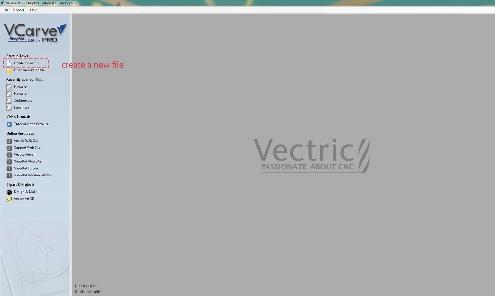
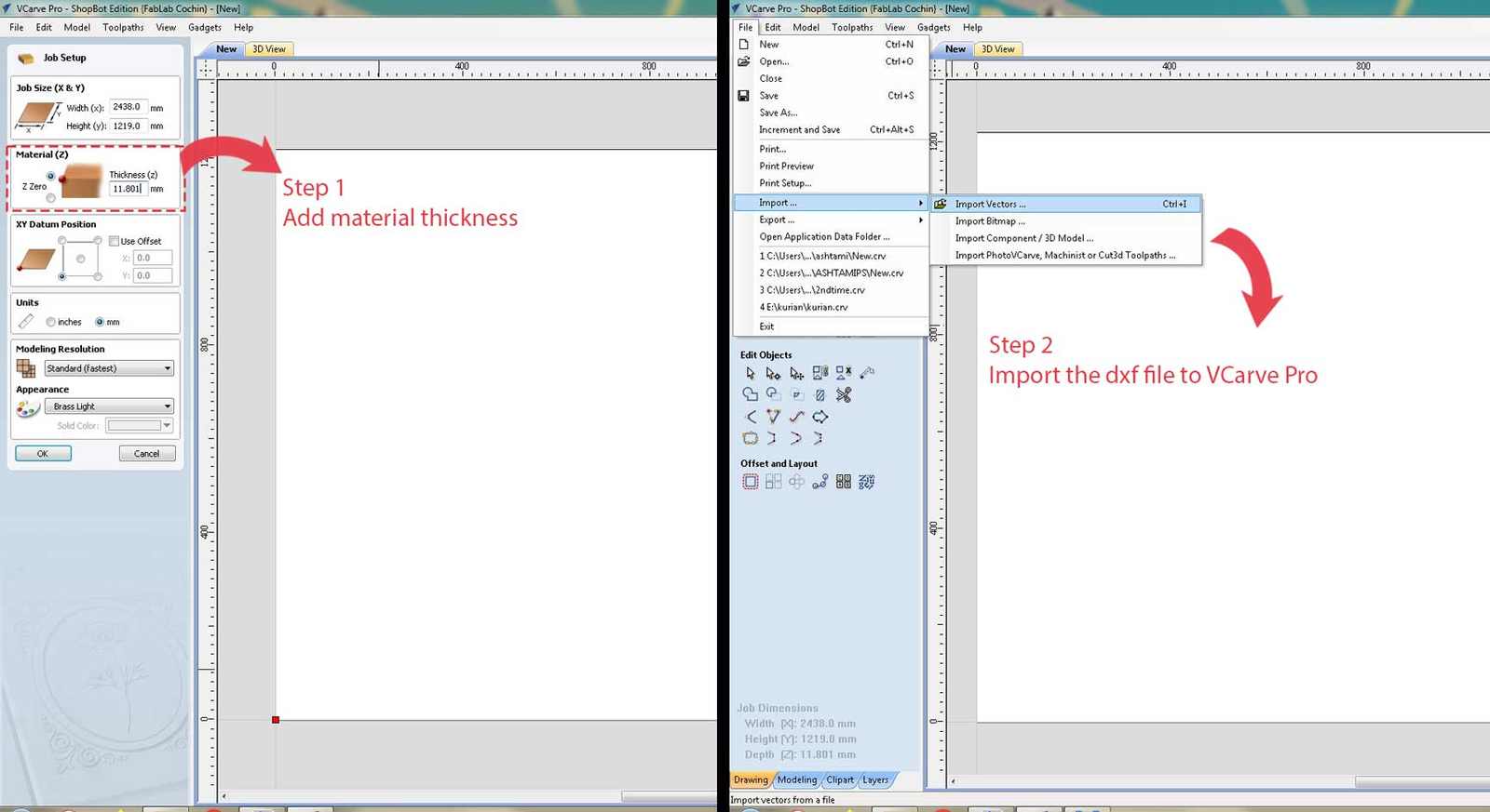
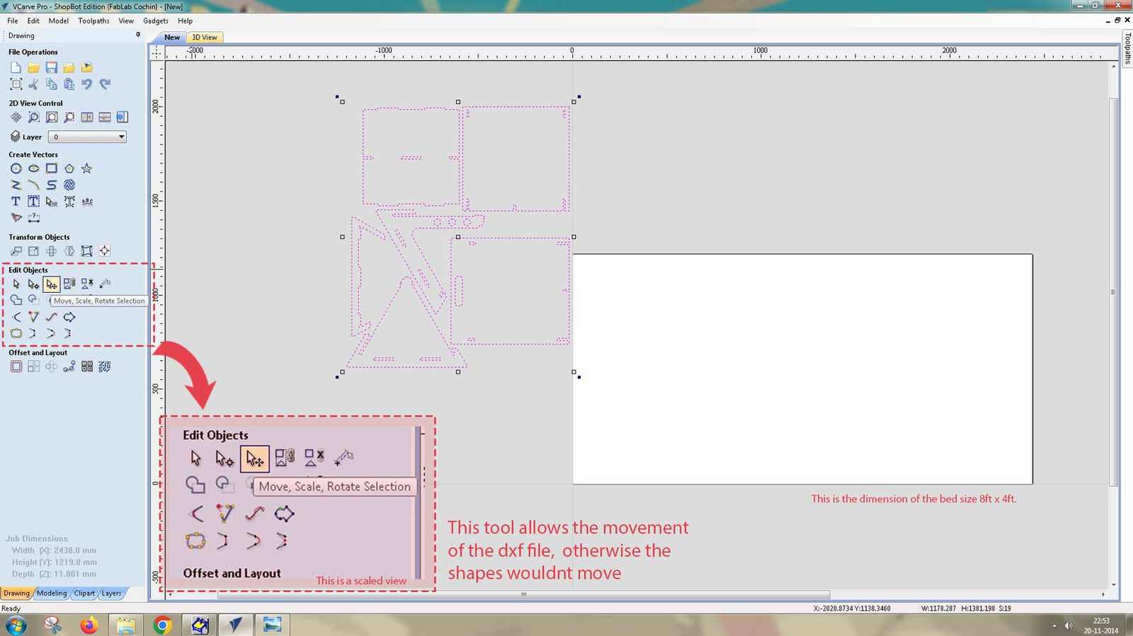
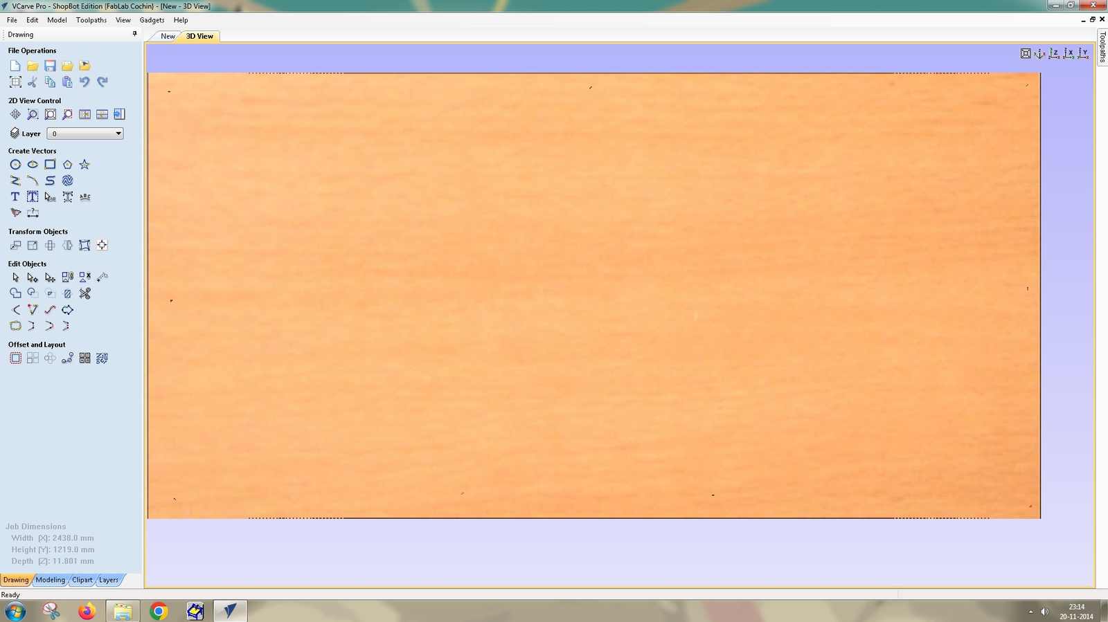
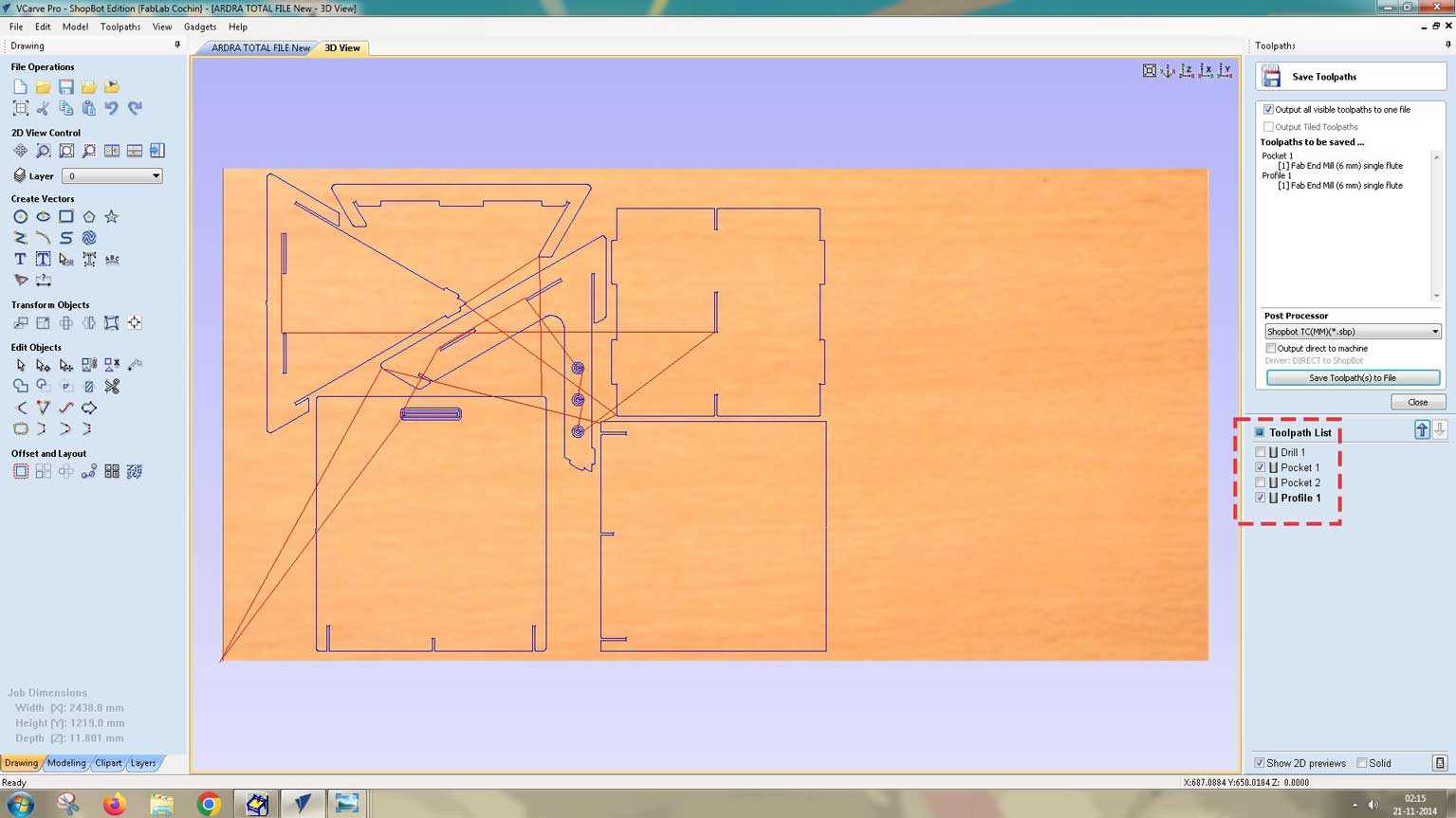
VCarve Pro
VCarve Pro is software used to create and cut designs on a CNC router. It is paid software and helps to control the toolpaths.
Yep there are 19 images! 😁 and it did take a long while to type it all 🥲.
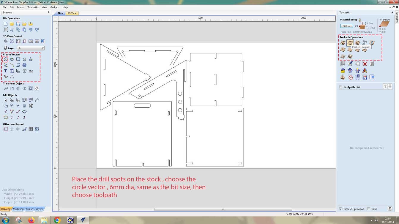
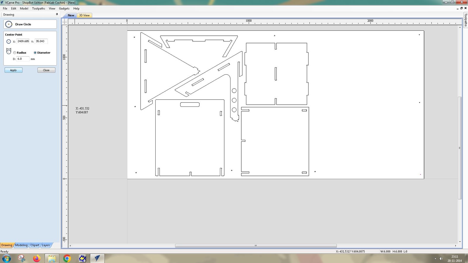
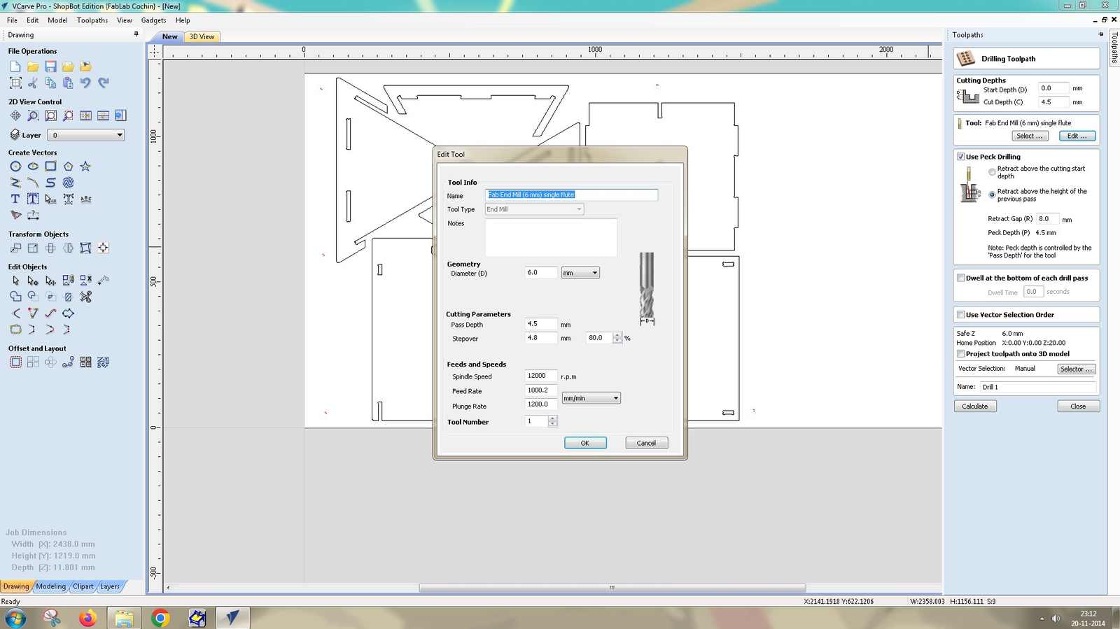
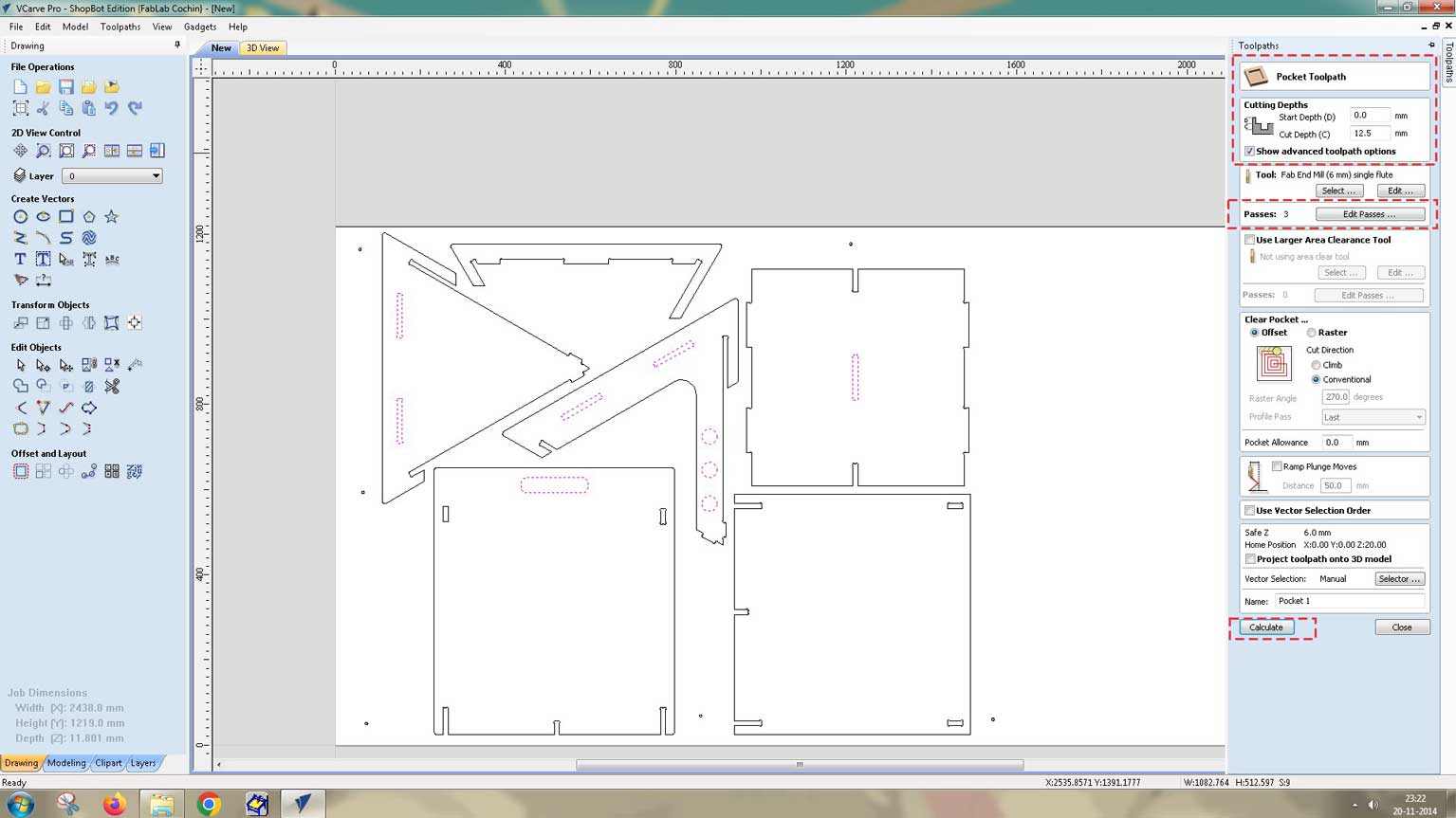
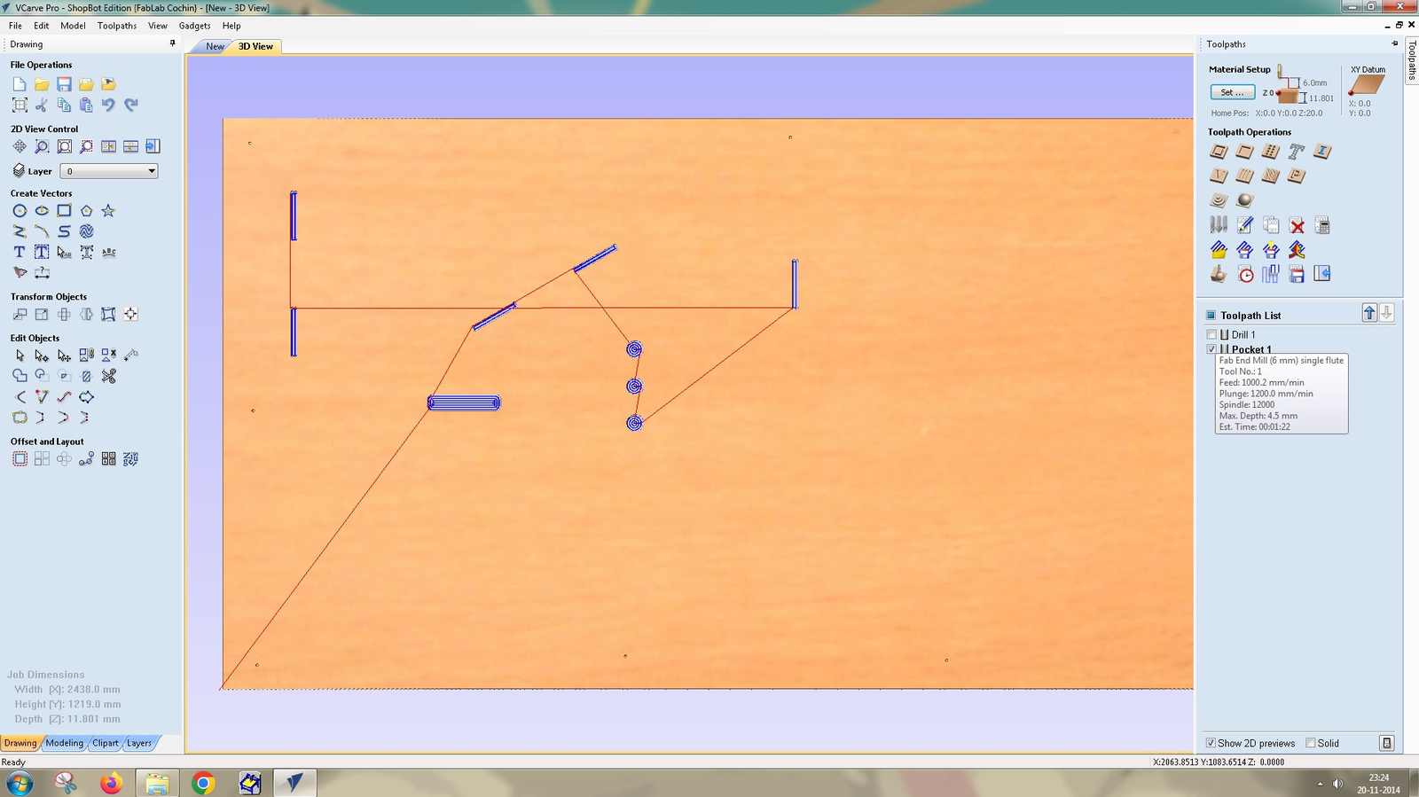
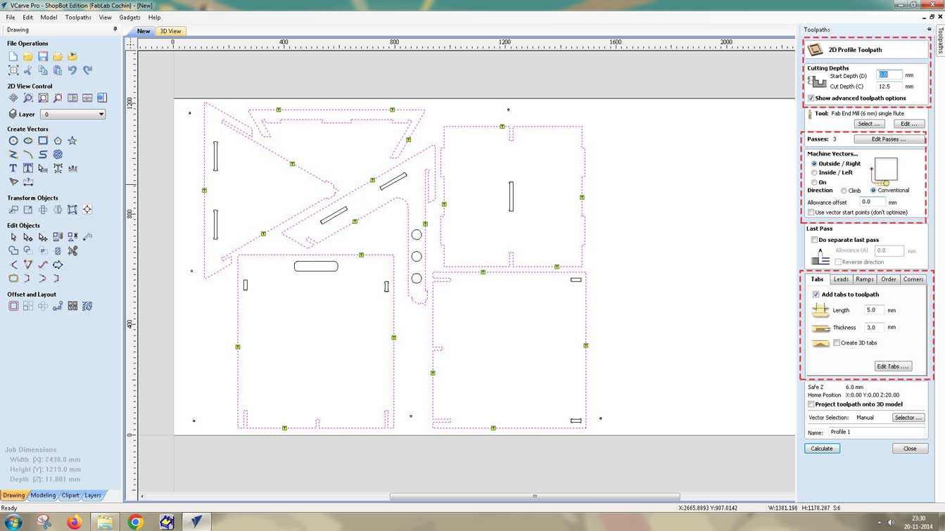
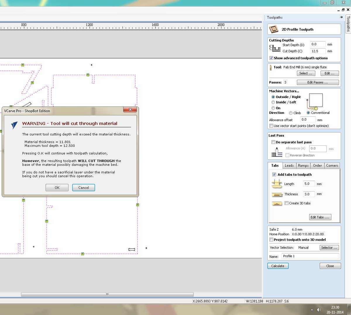
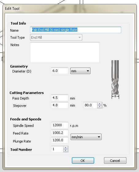
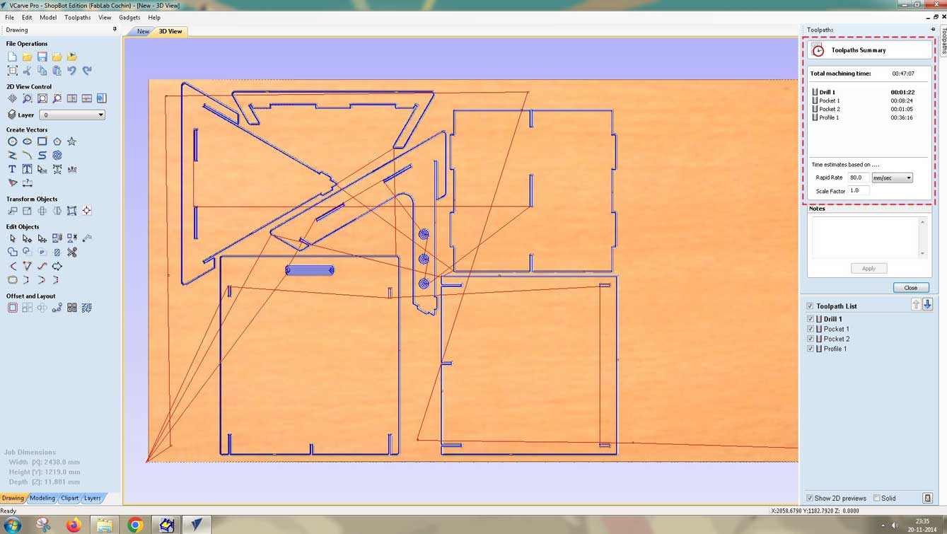
The parts were machined on a ShopBot PRS5 Alpha CNC router using a 6 mm single flute flat end mill. The material was 11.8 mm plywood from a 2438 × 1219 mm sheet. Toolpaths were generated in VCarve Pro with a
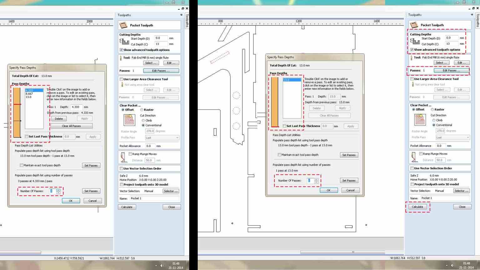
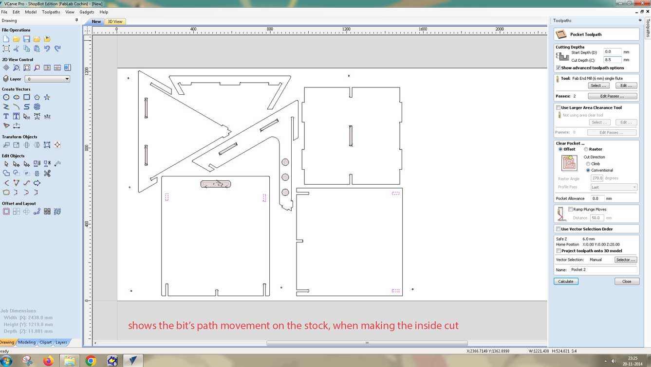
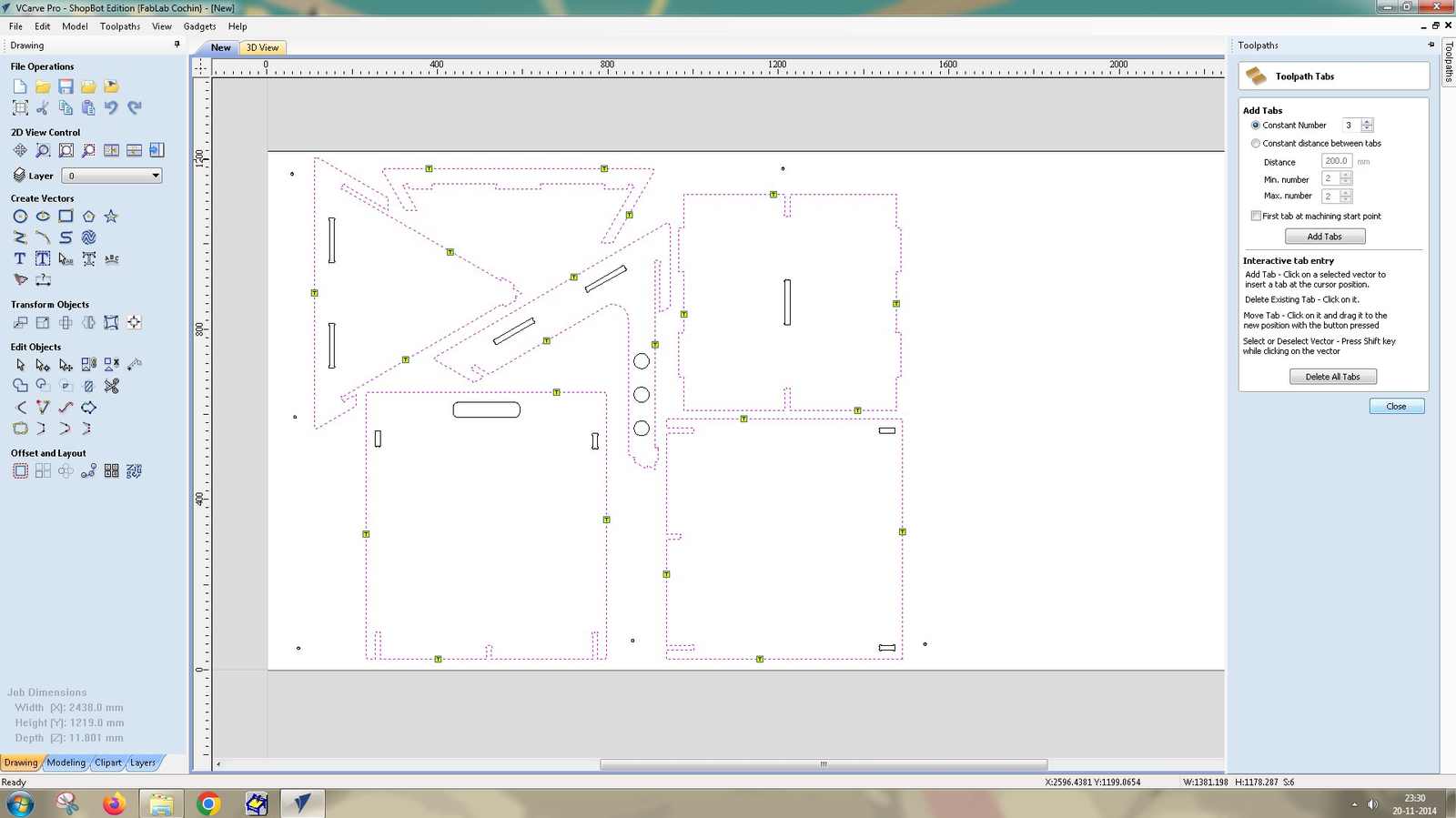
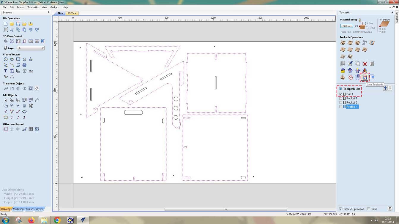
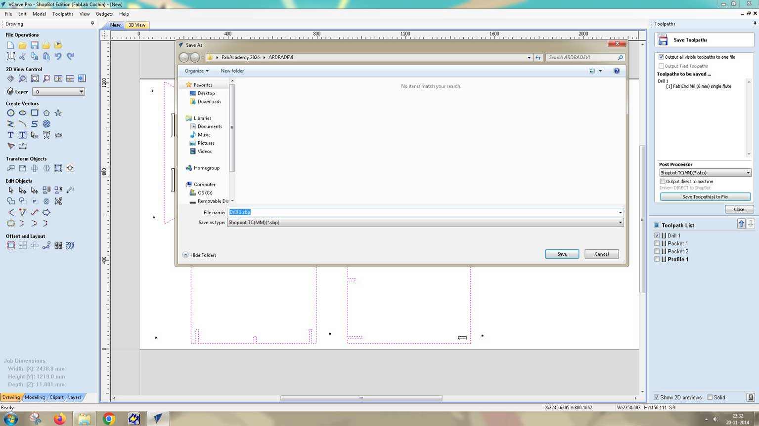
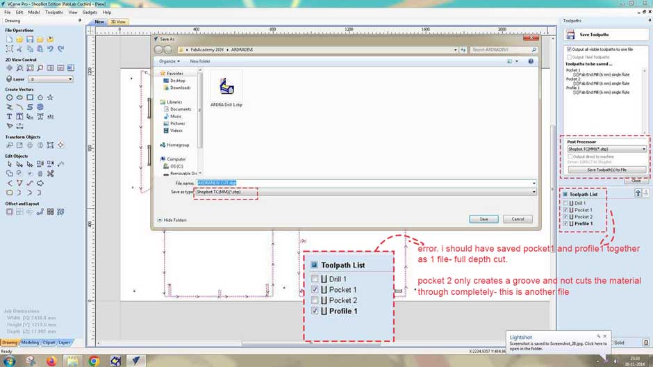
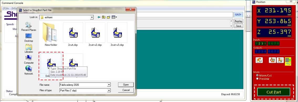
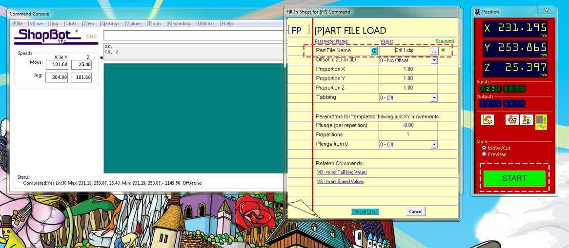
Saving Toolpaths
The toolpaths are saved as two different files.
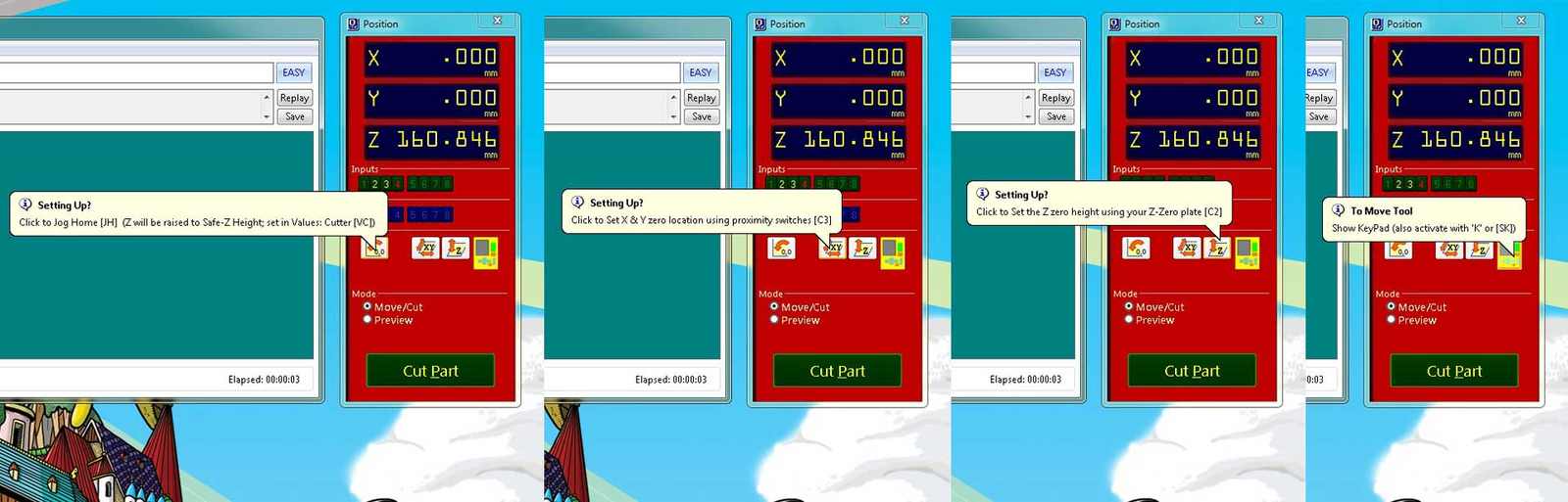
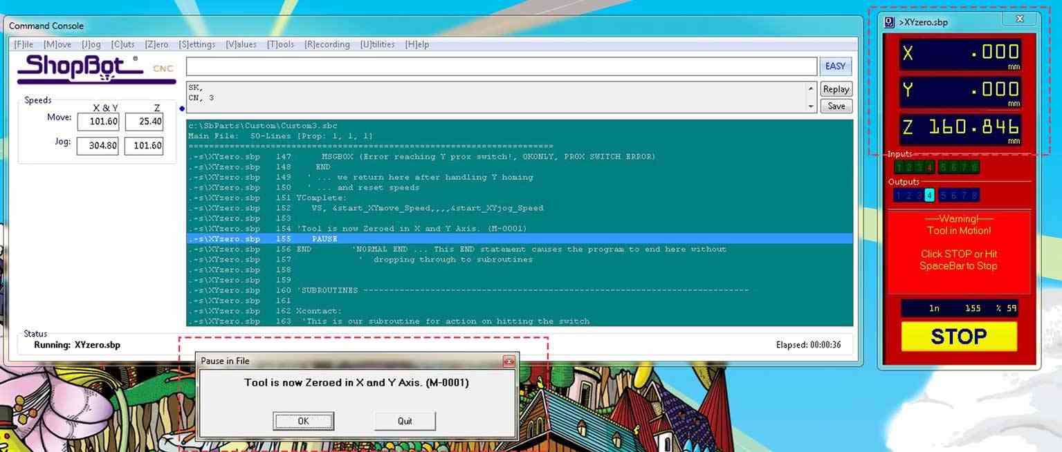
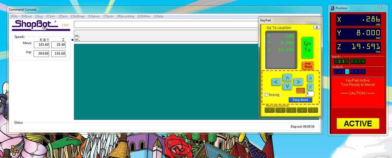
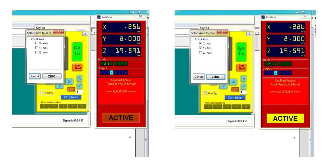
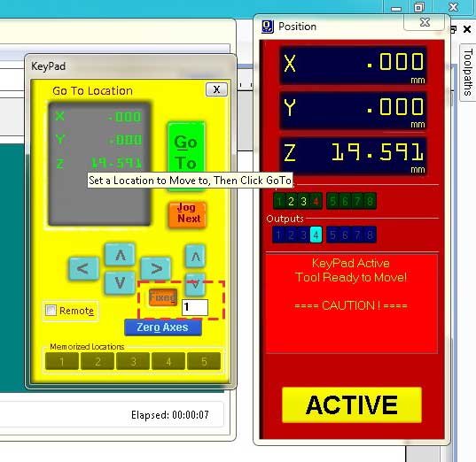
Job Control - Setting Zero Axis

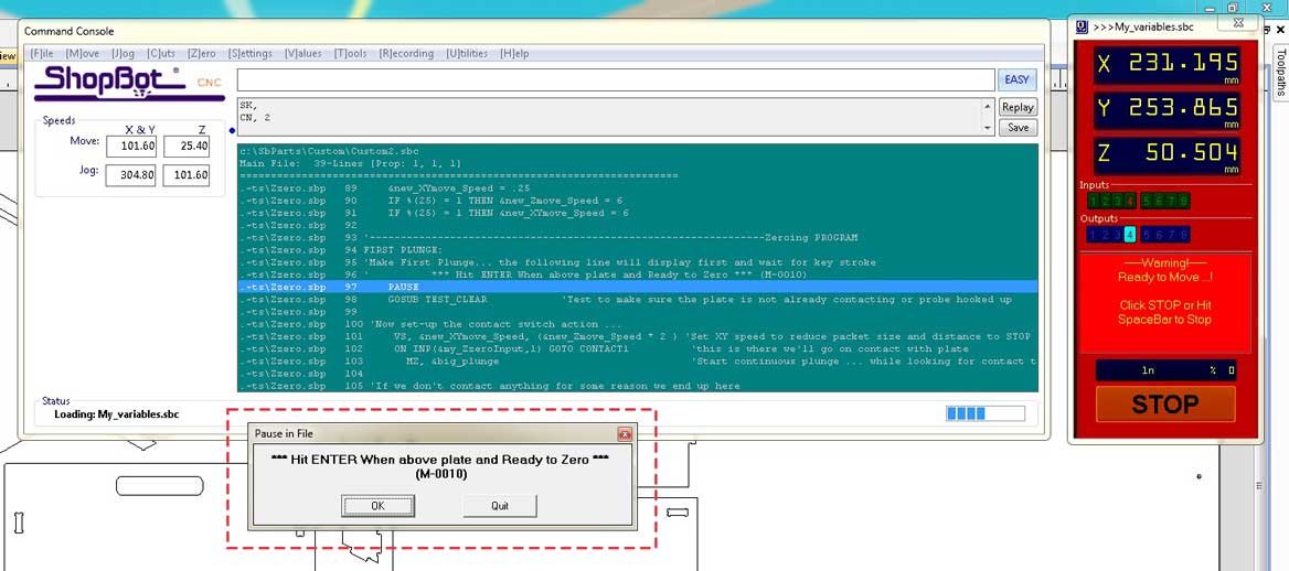
Route CNC
Finally, let's route it.
Yeah, it was a really long process, and then there is the process of post processing.
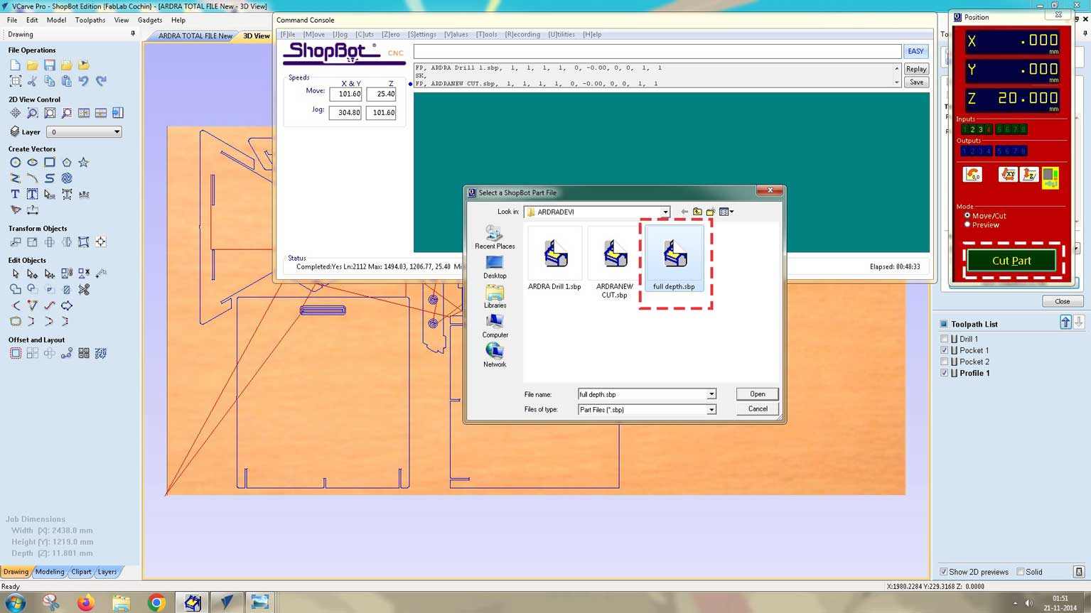
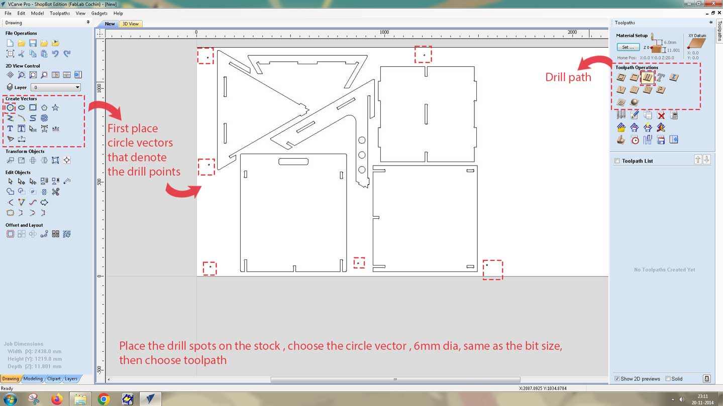
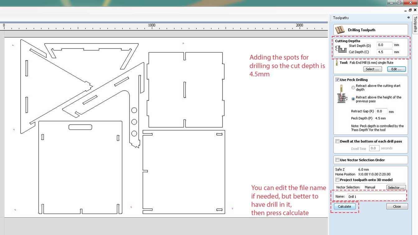
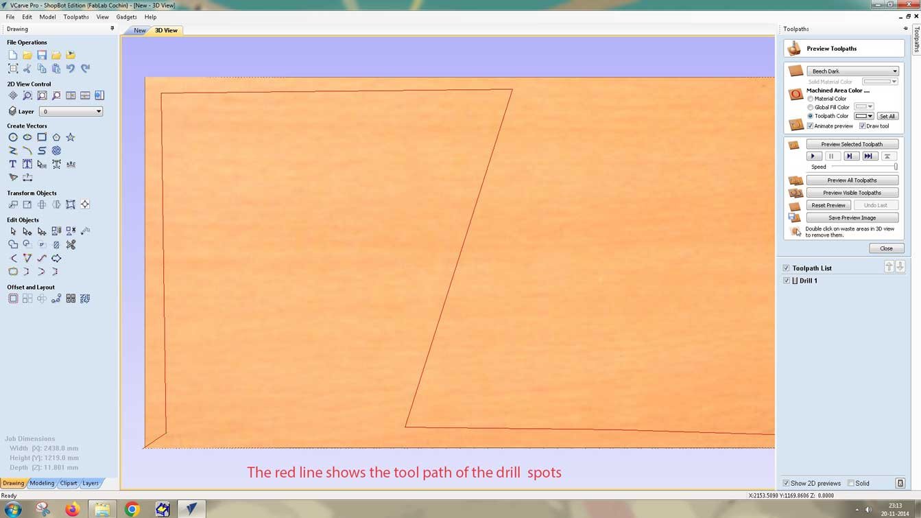
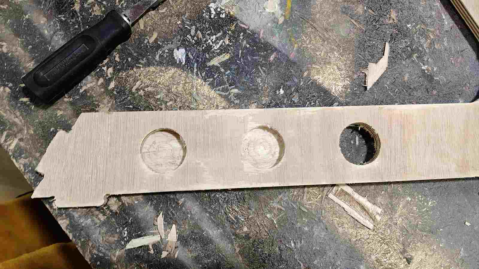
Drilling
Routing/h3>
Chiselling
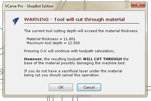
Since the stock had a warping issue, it did not cut through the material fully. I had to chisel it out using a chisel and hammer.
Sanding
After chiselling, I had to sand the parts. I used a handheld sanding machine.
Issues
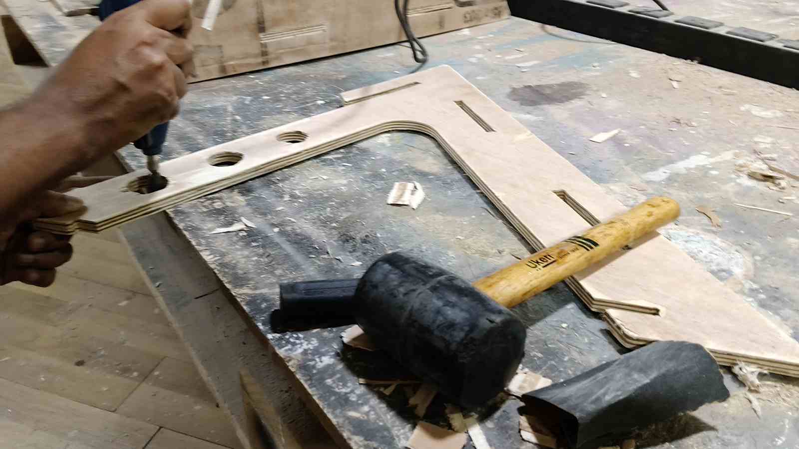
Assembling the parts
Use of mallets to hammer the joints together as the fit was tight.
Hero Shot
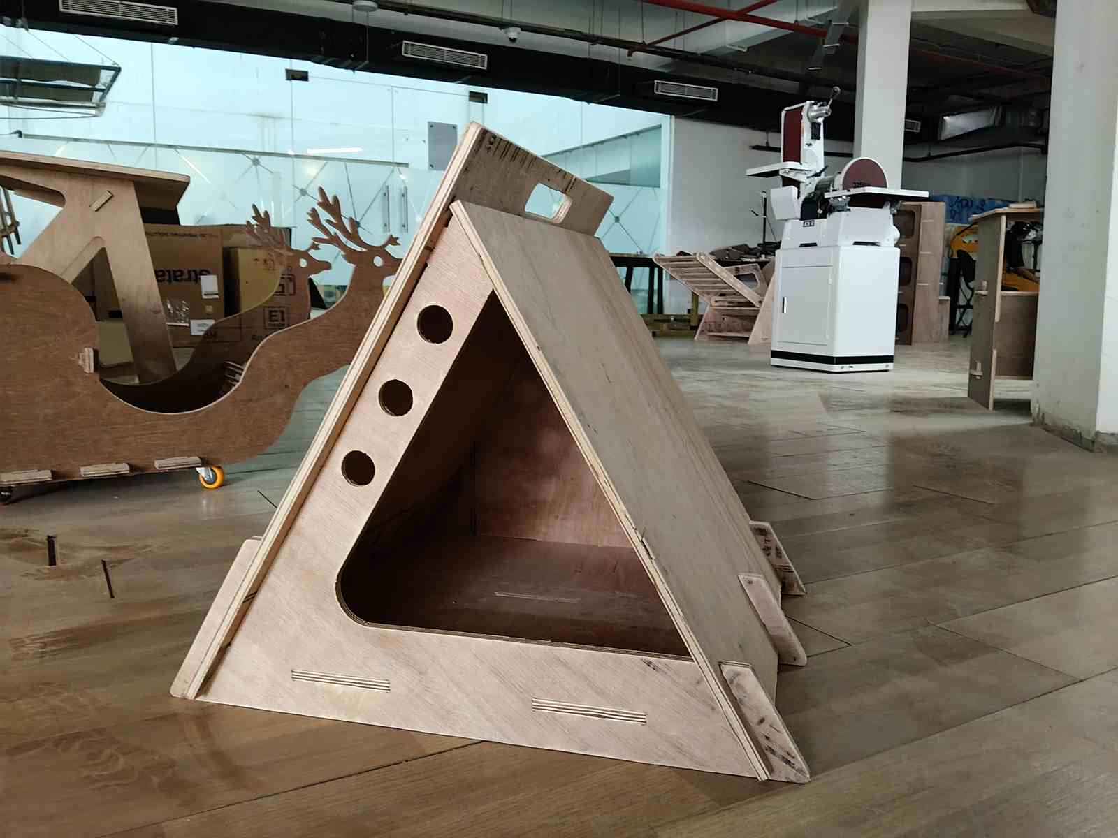
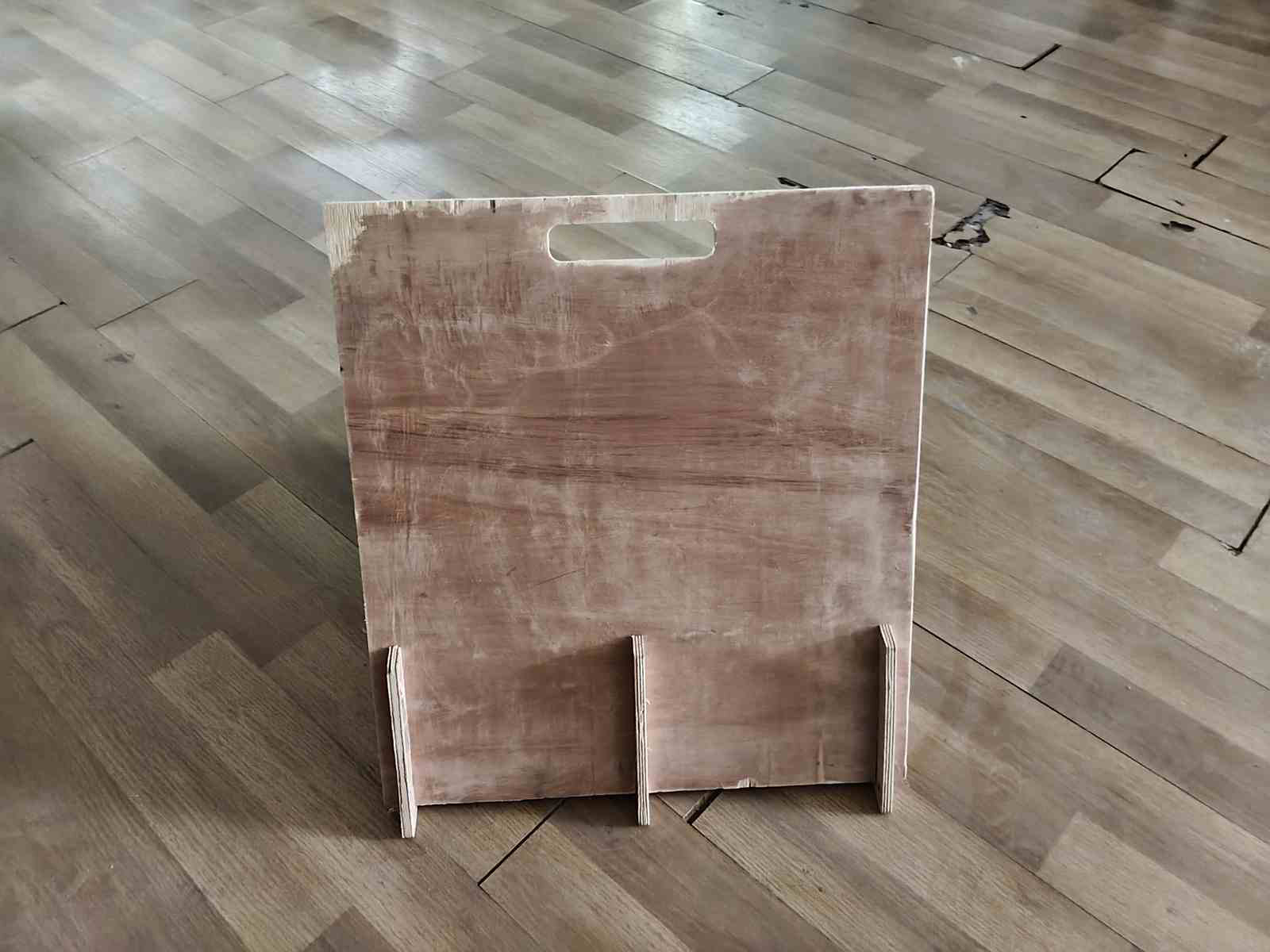
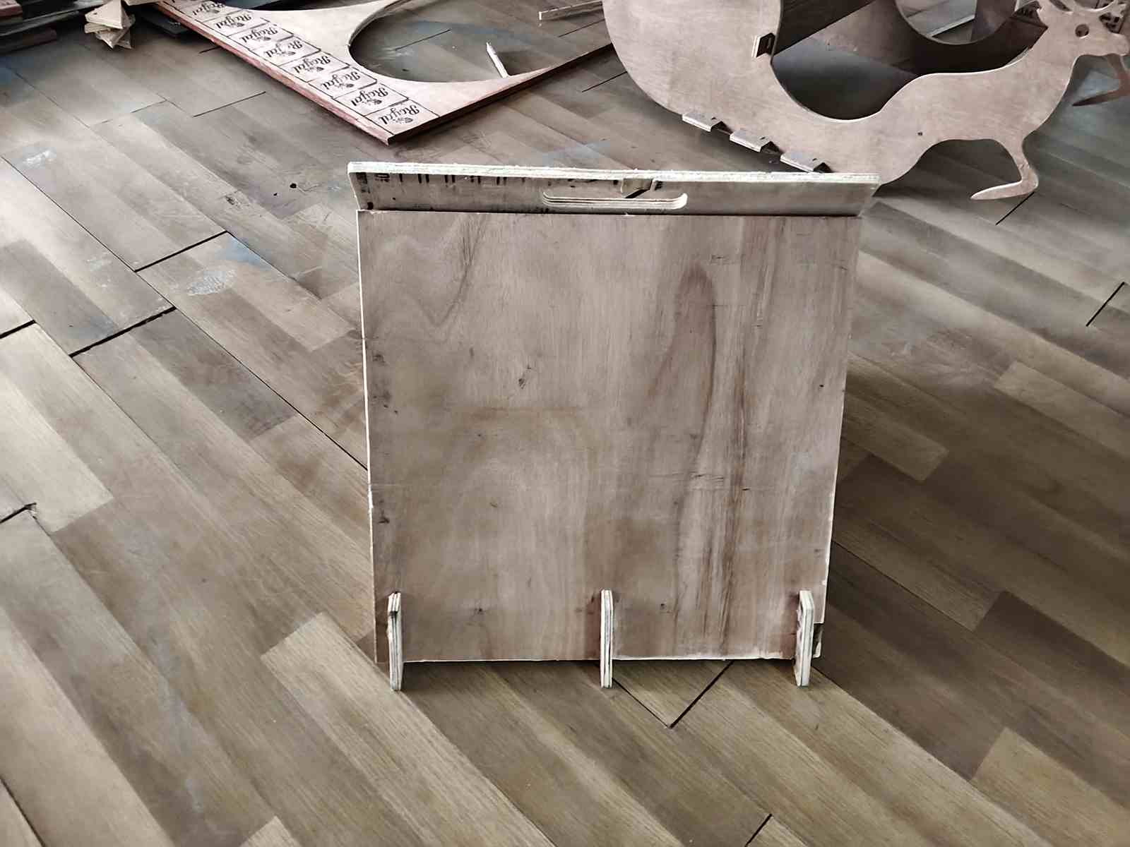
Lift test
I was able to lift the pet house by holding the handle.