Group assignment
Click here for this week's group assignmentIndividual Assignment
his week’s goal was to understand different input devices and integrate them with a microcontroller I designed. So i thought of trying out some essential elements for my final project, one is the touch sensor the other is a magnetic encoder.AS5600 - Magnetic Encoder
The AS5600 is ideally suited for contactless potentiometers,contactless knobs, pedals, RC servos and other angular position measurement solutions. I have decided to use Magnetic encoder as my input device . I read some basic datasheet to understand the working of the encoder .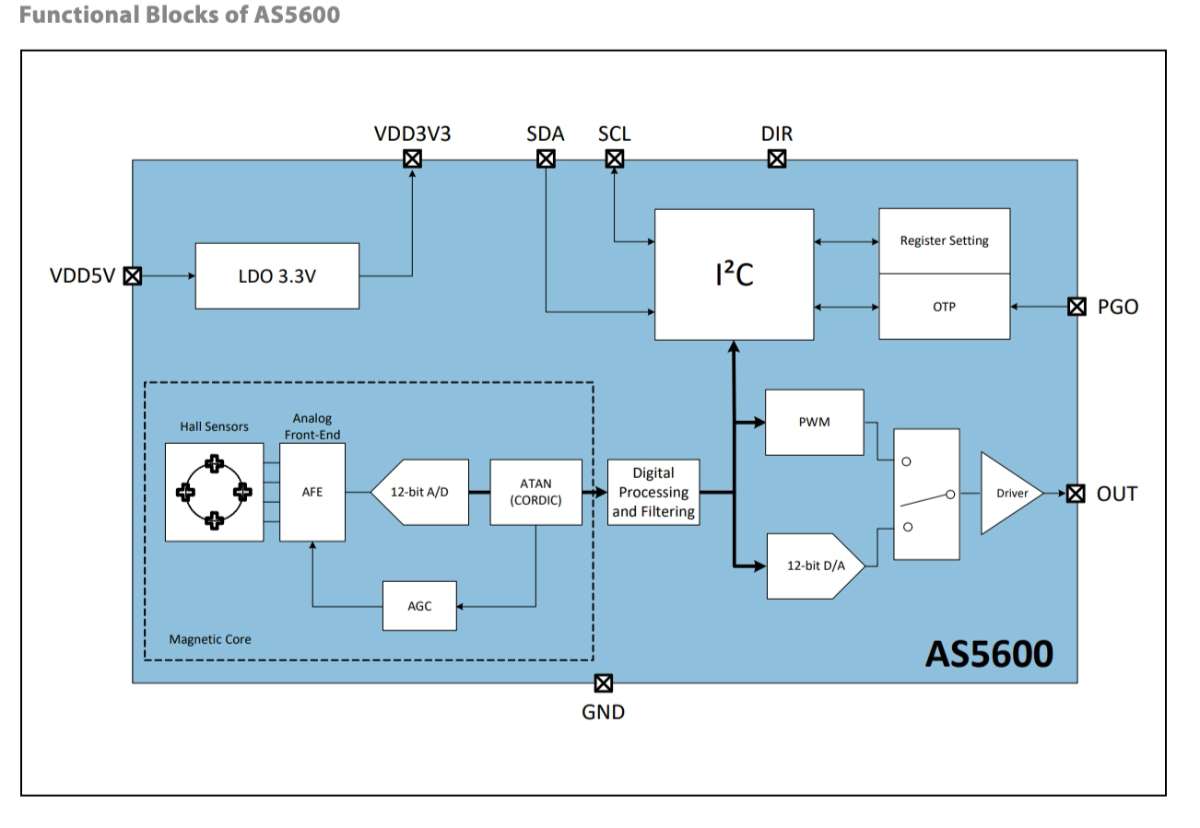 This is an amazing Youtube Video about the sensor.
Things to keep in mind while connecting the AS5600 are :
An input pin (DIR) selects the polarity of the output with regard to rotation direction. If DIR is connected to ground, the output value increases with clockwise rotation. If DIR is connected to VDD, the output value increases with counterclockwise rotation.
Capacitive Sensing
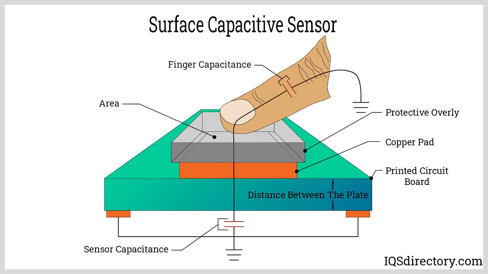 Capacitive touch Sensors detect objects by measuring changes in capacitance, which occurs when an object enters the sensor's electrostatic field, without needing physical contact.
To know more refer this PDF
Capacitive touch Sensors detect objects by measuring changes in capacitance, which occurs when an object enters the sensor's electrostatic field, without needing physical contact.
To know more refer this PDFATtiny3216
After learning and understanding how the sensors work i worked out the number of pins that were required for the sensors and the led and decided to use an ATtiny3216 .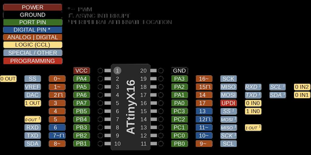
Schematic Diagram
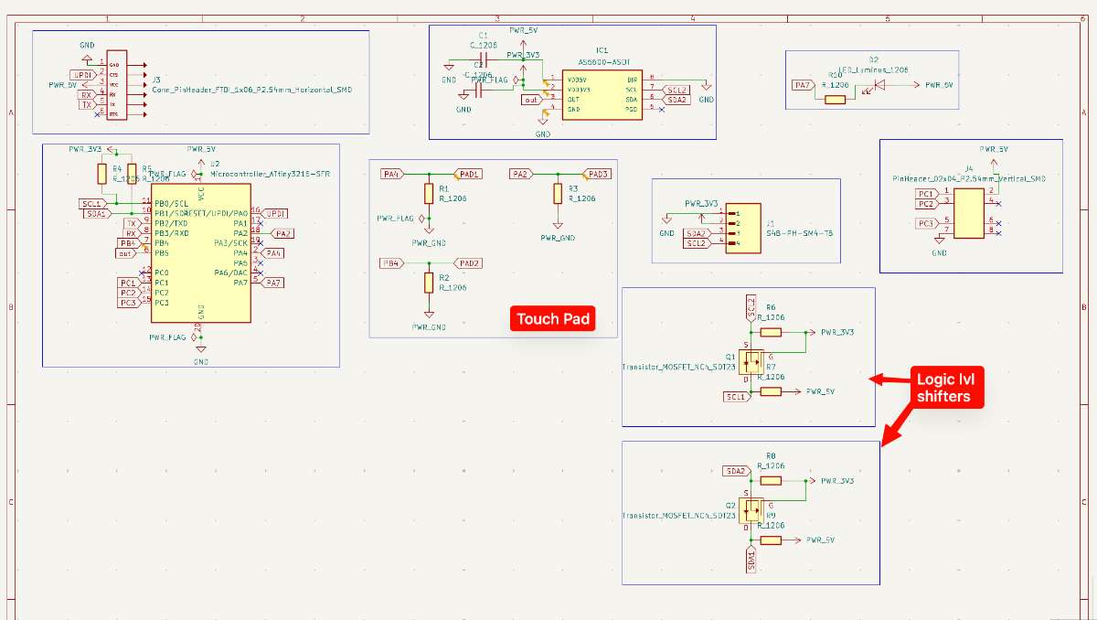
I went on to KiCD to make the schematics diagram . The AS5600 was not available in the fab library so i had to download the footprint from snapEDA and then import the symbol and assign the footprint.
A logical level shifter (or converter) is an electronic component that enables communication between devices operating at different voltage levels, in this case my ATtiny functions on 5V and my encoder only takes in 3.3V so to make that voltage shift i used the level shifters, by safely translating signal voltages. For this you need a transistor
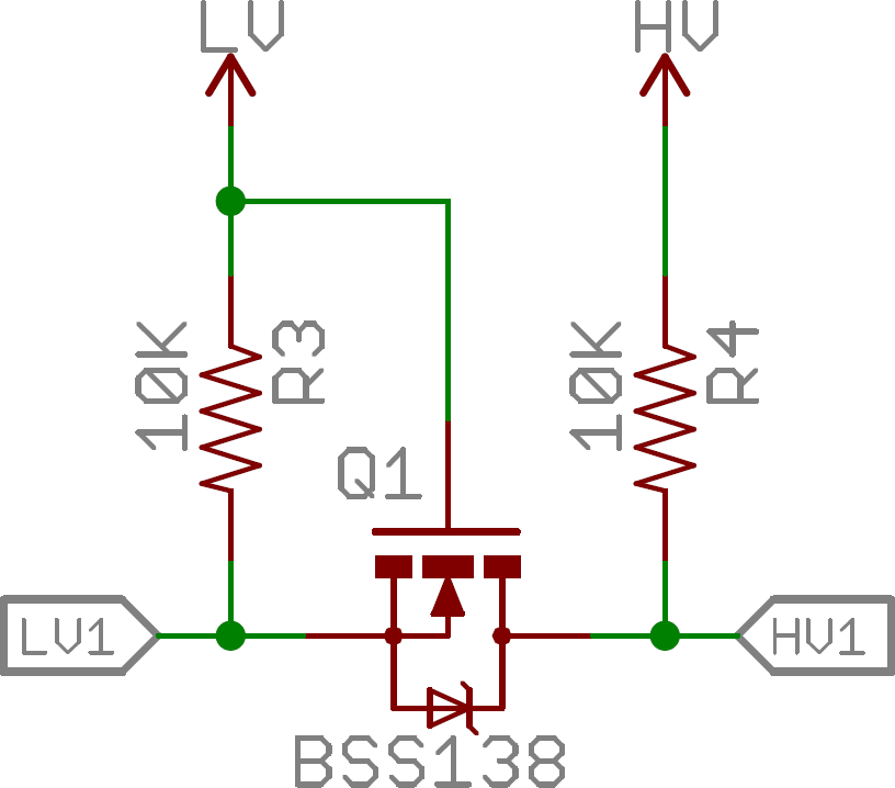
For the touch pad i referred Namita's documentation
The final schematic looked like this.
 Schematic Diagram
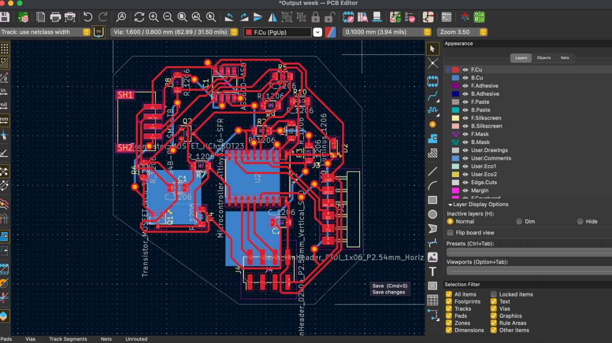
Next i opened the PCB editor > Update PCB, to start with routing the traces.
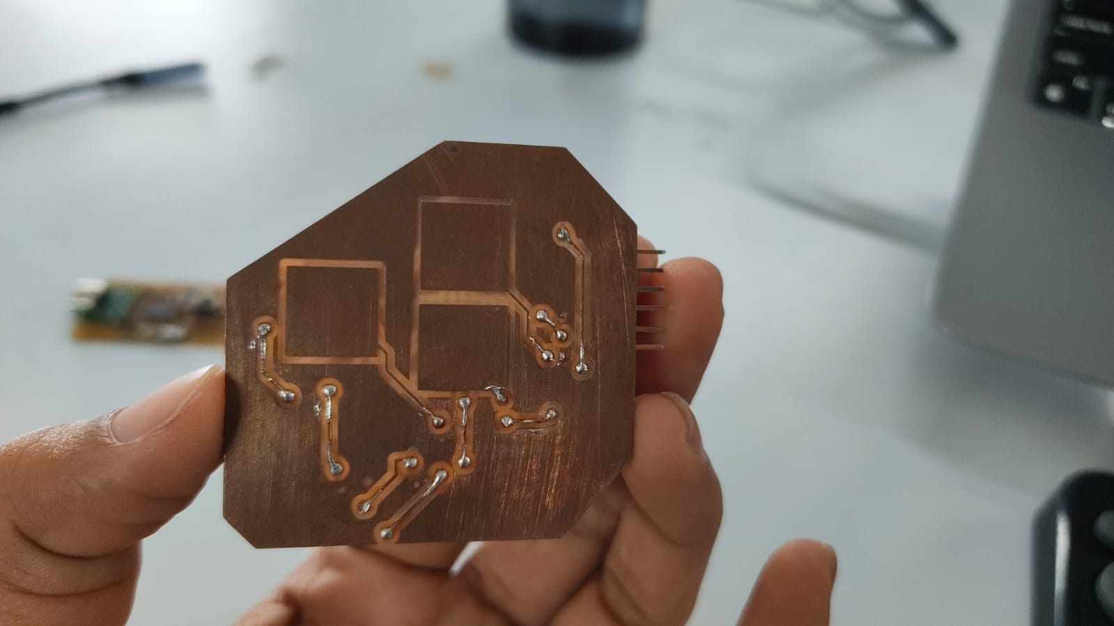
Here, i am using a double sided PCB this way it is easier to incorporate everything. Since we have to use a touchpad , i drew 3 rectangles in the Kicad Editor under the edgecut layer.
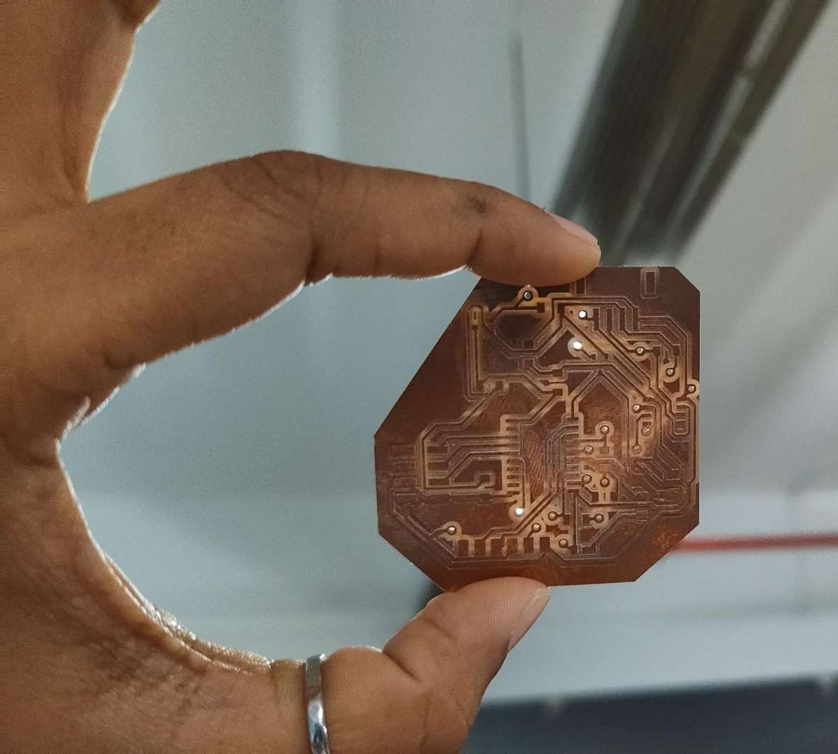
this is how the final pcb looked:
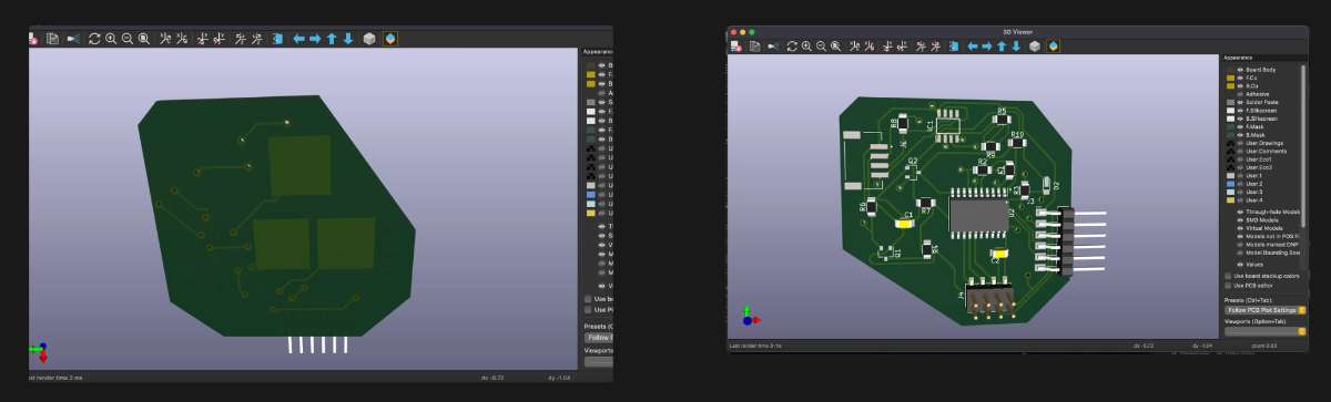
 These are the 3D views:
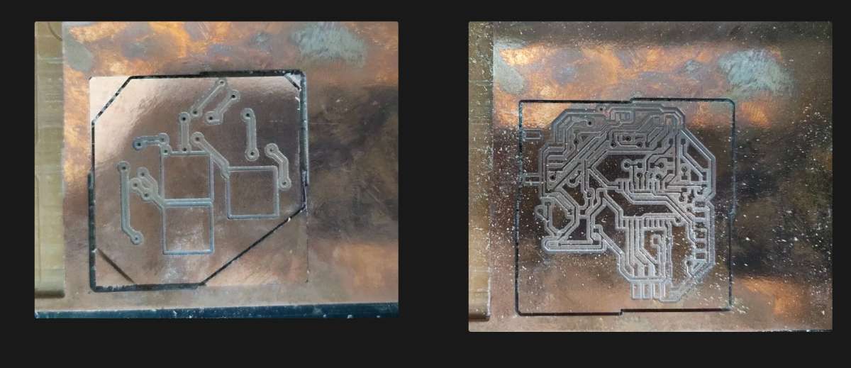
 Then i milled the PCB:
 And then 1 assembled the components required.
 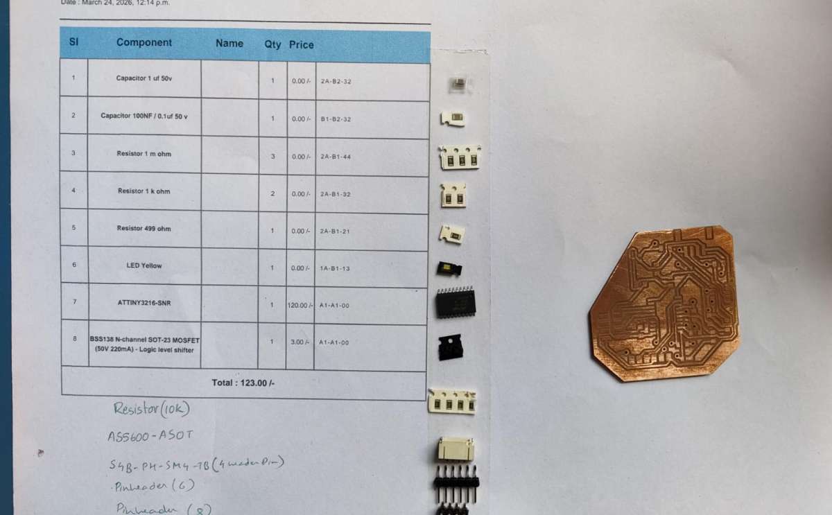 And I soldered the PCB.
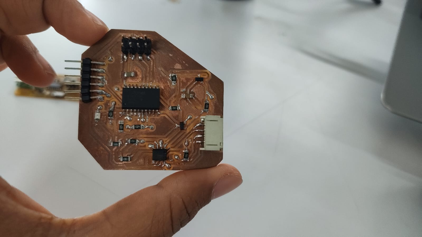
 And checked if there are any shorts, found one and fixed it.
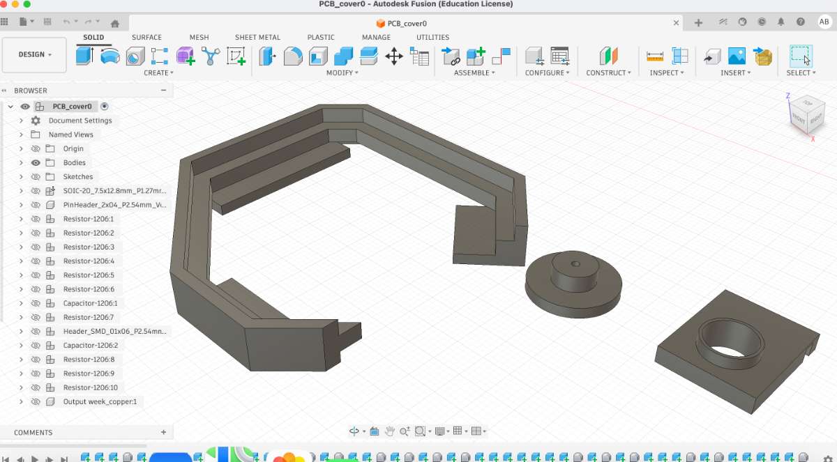
Designing the PCB Case
For the sensors which i chose, i found out that the AS5600 needs a case which allows a magnet to be placed directly over the sensor. My instructor showed me Thomas's Academy journal and i got an idea of how i should make it.
The following is the Design that i made.
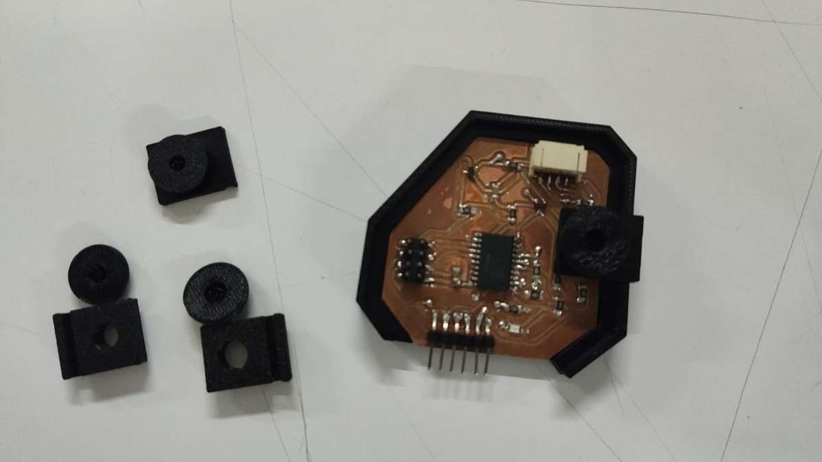
 Then i proceeded to 3d print them, the initial ons were a flop but after a few correction
it was all good.
Then i proceeded to 3d print them, the initial ons were a flop but after a few correction
it was all good.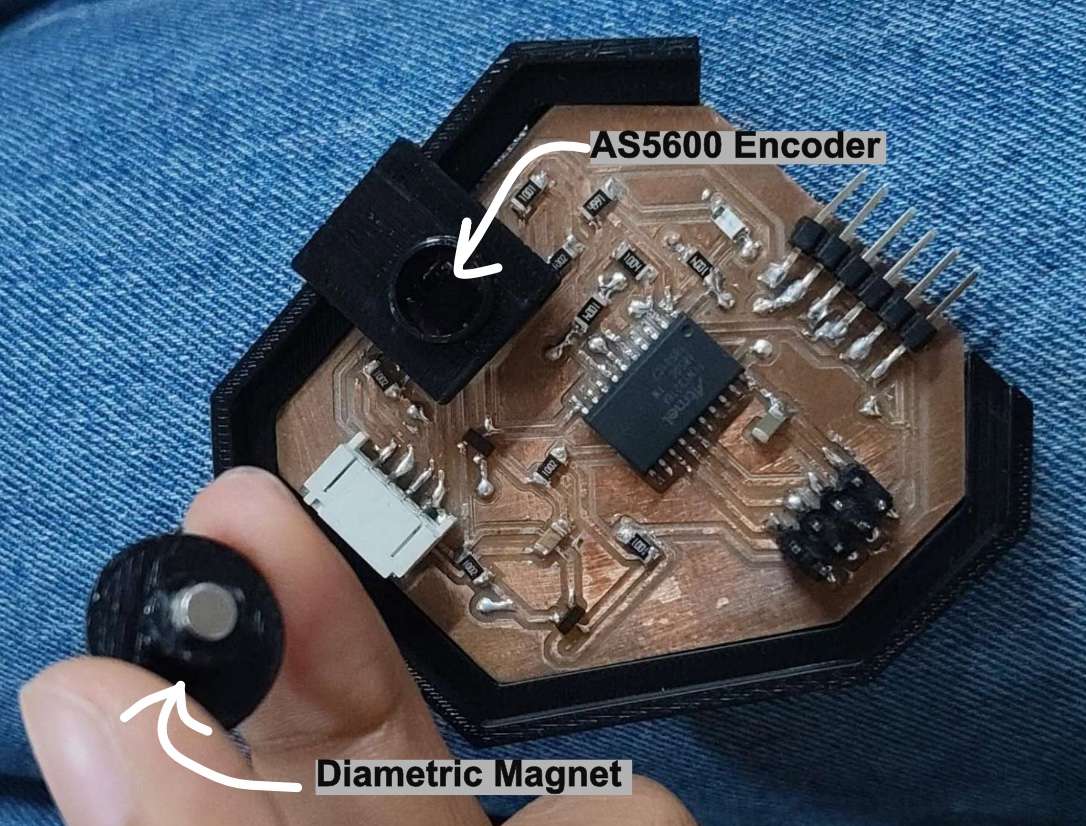
 Hero shot :
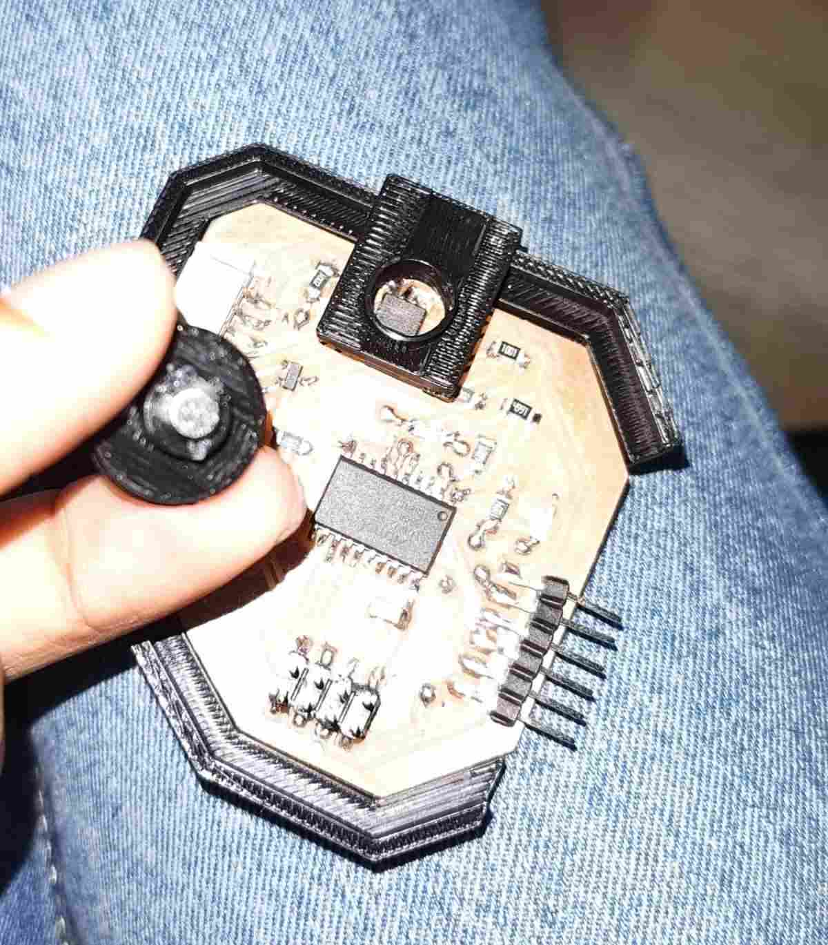
Programming the PCB
I referred Kevin's documentation on How to program an ATtiny.
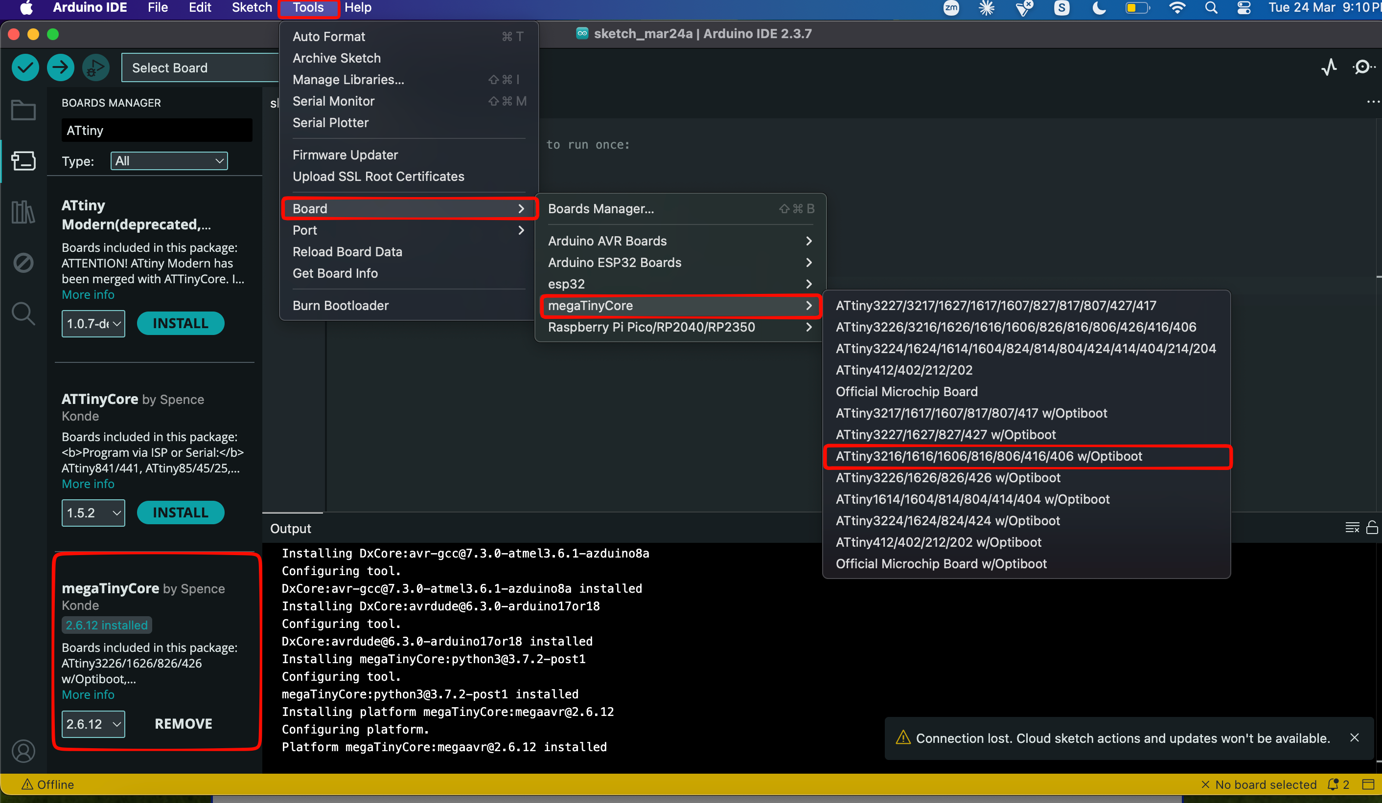
To set up the ATtiny board in Arduino IDE, add this link to the Additional Boards Manager URLs.
http://drazzy.com/package_drazzy.com_index.json
Now, in Boards Manager, install MegaTinyCore to your local libraries and follow as shown in the image.
first i tried out the touch sensors:
click here for code
Then i tried the encoder:
click here for code
Conclusion
This week was a good chance to test two of the input devices I'm planning to actually use in my final project, the AS5600 magnetic encoder and a capacitive touchpad rather than just picking sensors at random. Designing one board around both of them meant I had to think properly about pin count and how the parts would physically sit together.
The part I learned the most from was the voltage mismatch. My ATtiny3216 runs on 5V but the encoder only takes 3.3V, so I had to add a level shifter to safely translate the signals between them.
It wasn't all smooth. I found a short on the soldered board and had to track it down and fix it, and the first few 3D printed cases for the encoder were flops before I got the fit right, the case mattered here because the AS5600 needs a magnet sitting directly above it to work. Getting through both of those felt like real progress.
By the end I had a working board reading both the touch sensor and the encoder, which is exactly what I needed to prove out before committing them to my final project.
Final Files
PCB FilesPCB Case
Code File