Week 9: Input Devices
Group Assignment (link): probe an input device's analog levels and digital signals
Individual Assignment: measure something - add a sensor to a microcontroller board that you have designed and read it
Group Assignment / Oscilloscope
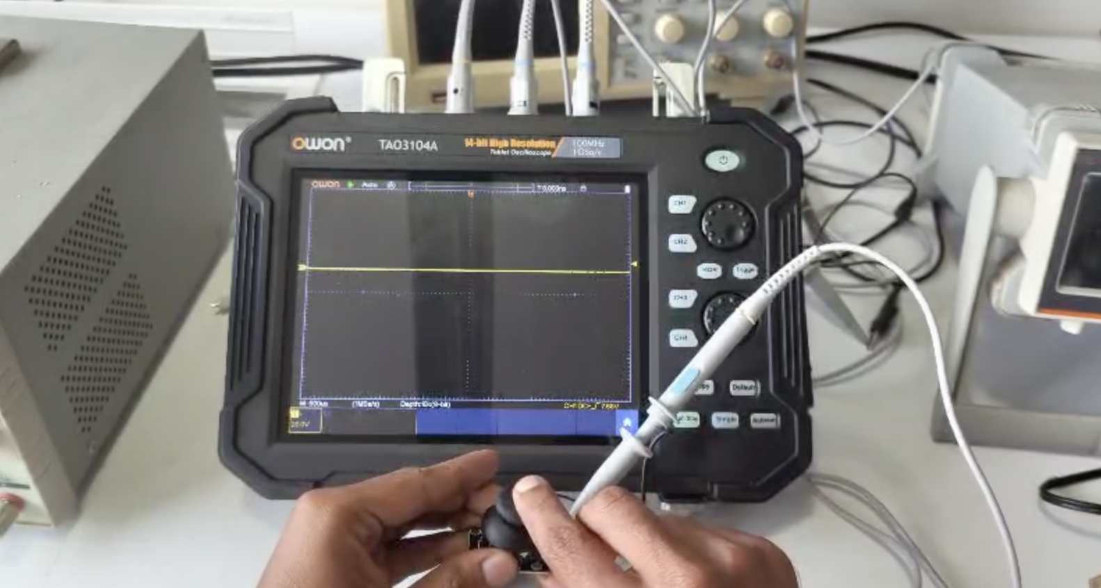
In the group assignment, we were meant to measure the output signal (voltage) of an input device visually by means of an oscilloscope. The group did that and documented on the group page. Two input devices were examined, namely a microphone and a joystick. For this to work, the device should be connected to power, and a probe from the oscilliscope connected to the output pin of the device to recieve the signal. It worked fine. Below is a screengrab of measuring the voltage of the joystick.
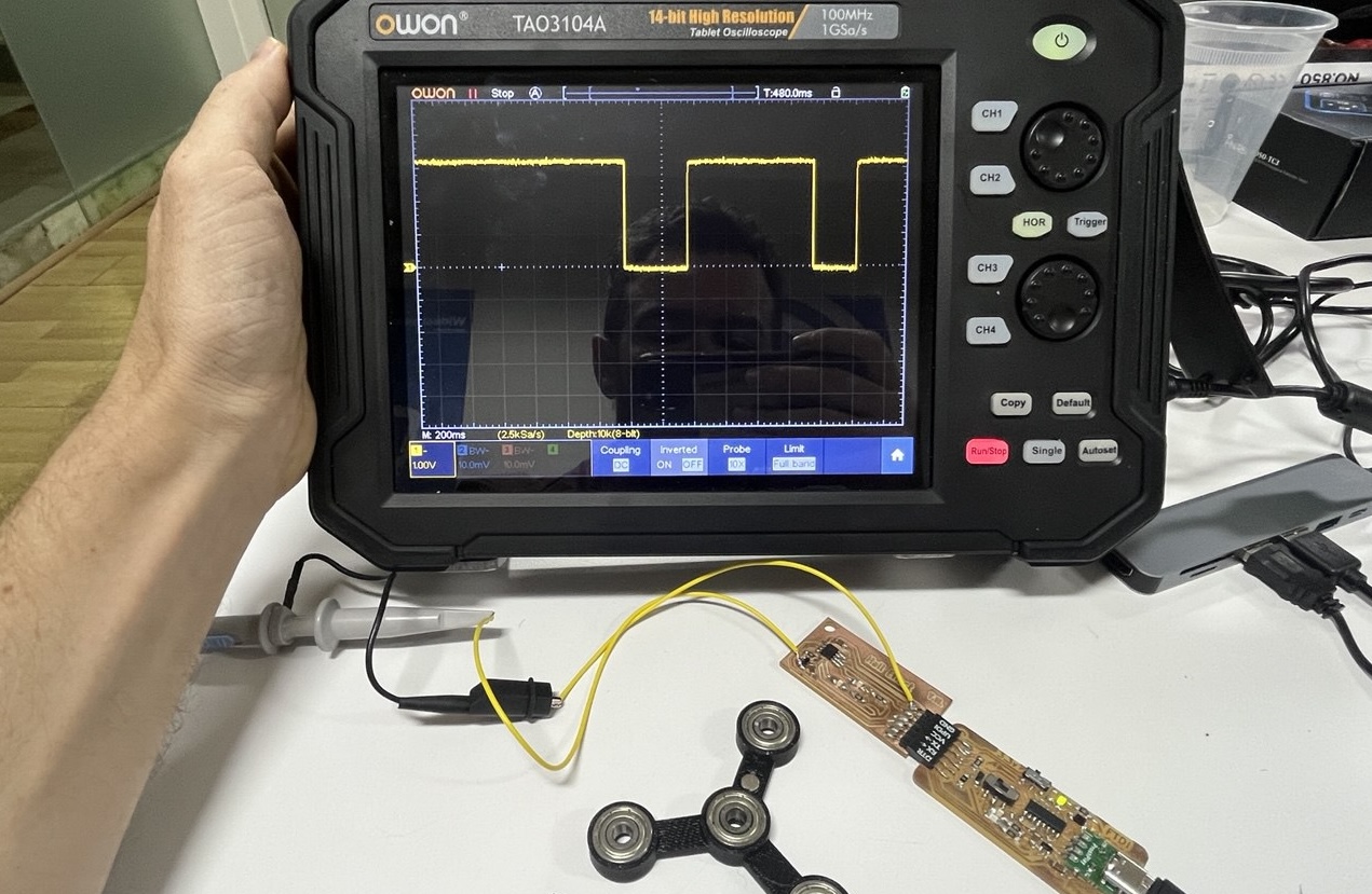
As we were many in the group, I also later went back to review my understanding and used the same oscilliscope to measure the output of my (digital) Hall effect sensor. As shown below it works and with clear digital result (detection / non-detection of magnet).
Hall Effect Sensor
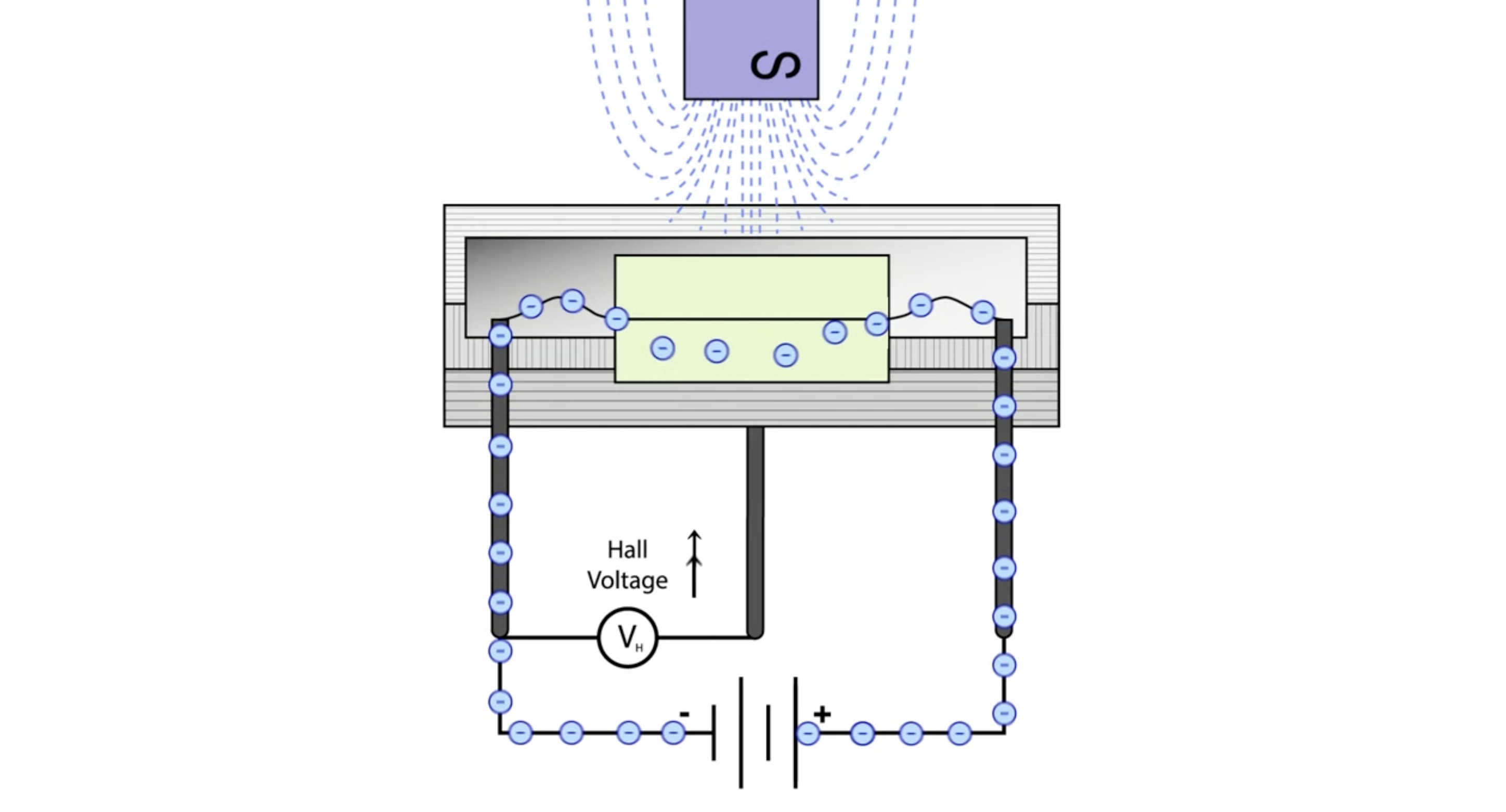
I chose this sensor because it is new for me, interesting, and could also come in handy for my final project. Basically a Hall Effect Sensor measures the presence and strength of magnetic field. The screenshot below is from a wonderful tutorial video from element14.
The video highlights a number of nice features of this sensor, namely:
- Entirely electronic
- Non-contact (no wear)
- (extremely) low maintenance
- Strong, robust design
- Immune to vibration and dust
All these features mean it will a reliable sensor to include in a durable final project!
Board with Hall Effect Sensor!
Since we want to use a Hall Effect Sensor and since wires are forbidden, we must make a new board. Let's go!
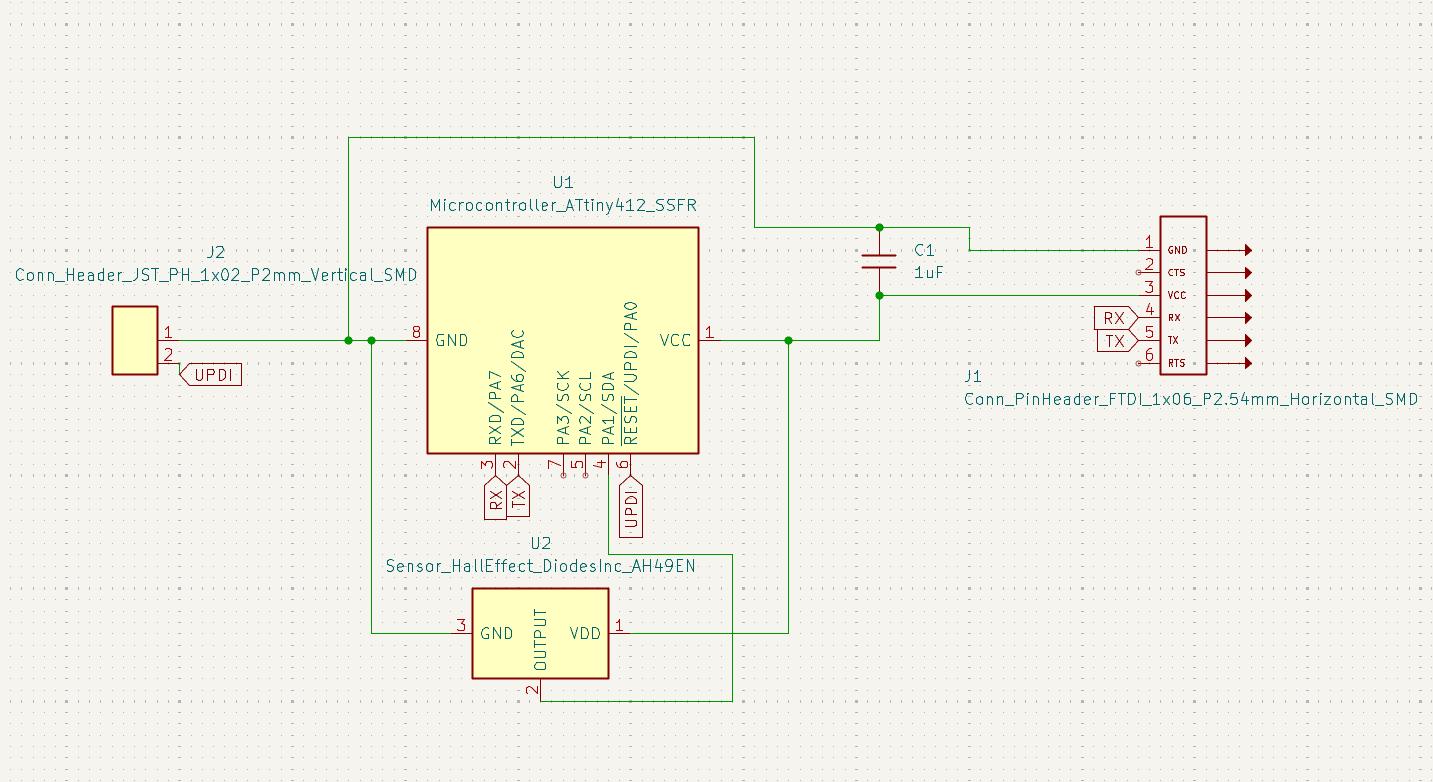
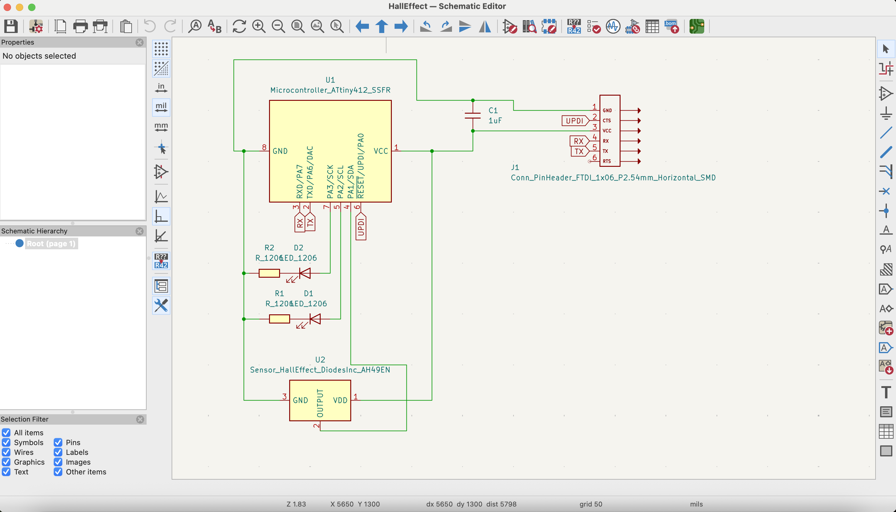
Fortunately Dr. Neil has the schematic and image for a simple board with Hall Effect Sensor using Attiny. Thank you!
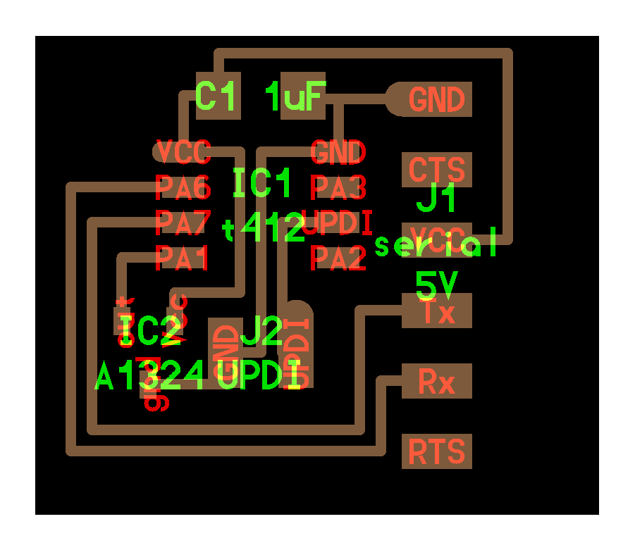
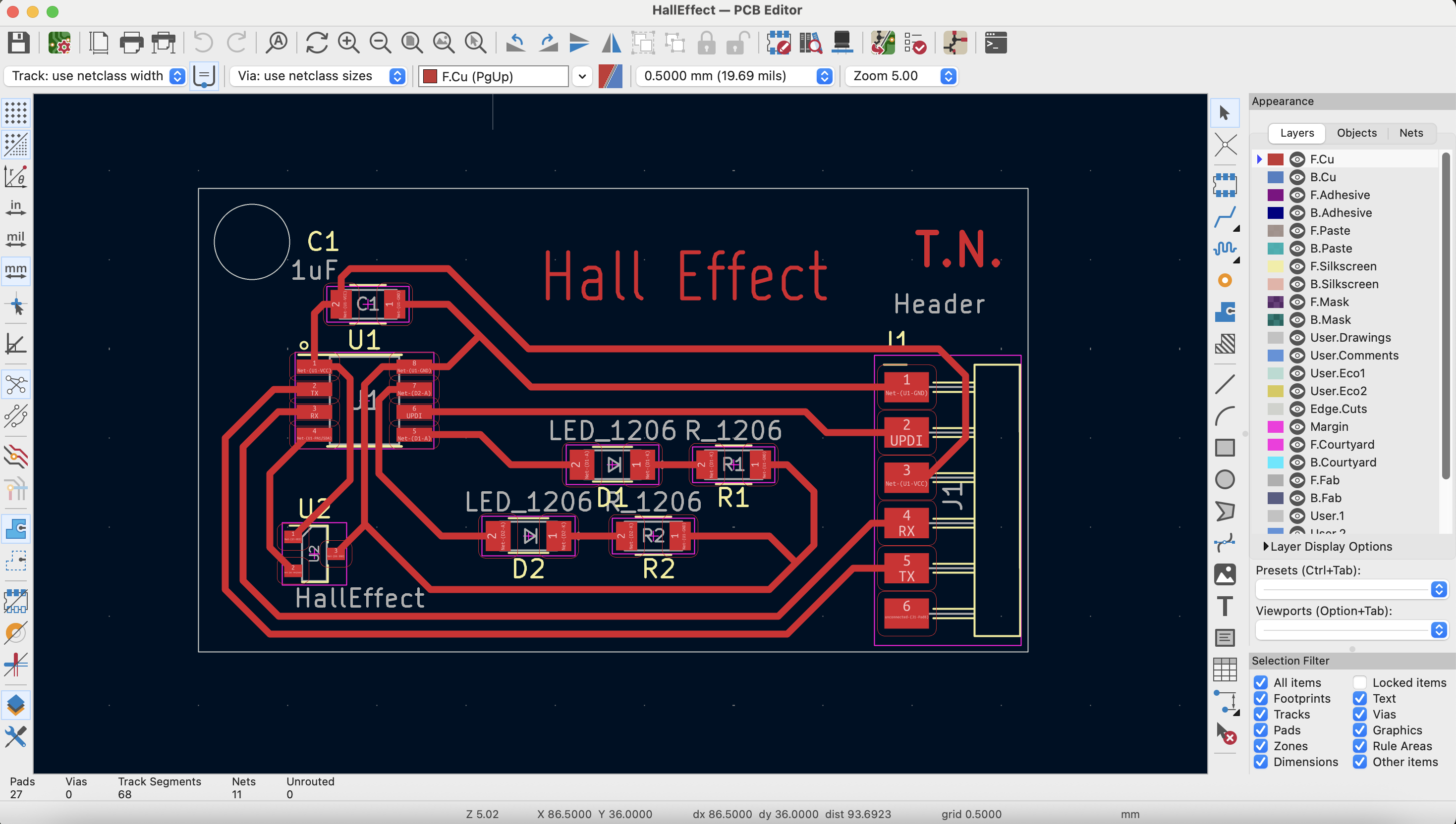
Here's my schematic and the PCB design using the Kicad software:
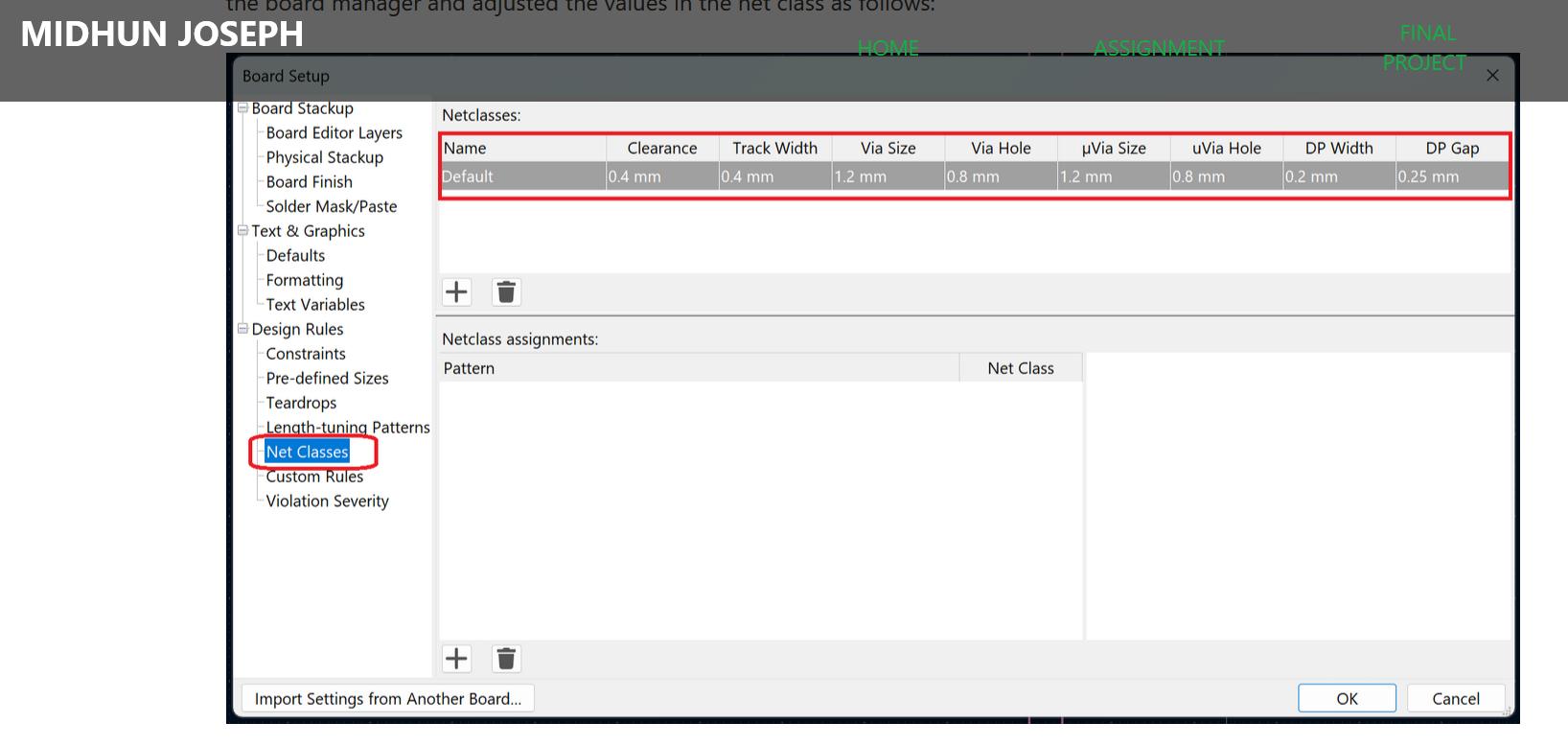
It happened that Mithun walking by, noticed that the traces seemed thin, and thus commented that I didn't properly do the board set-up:
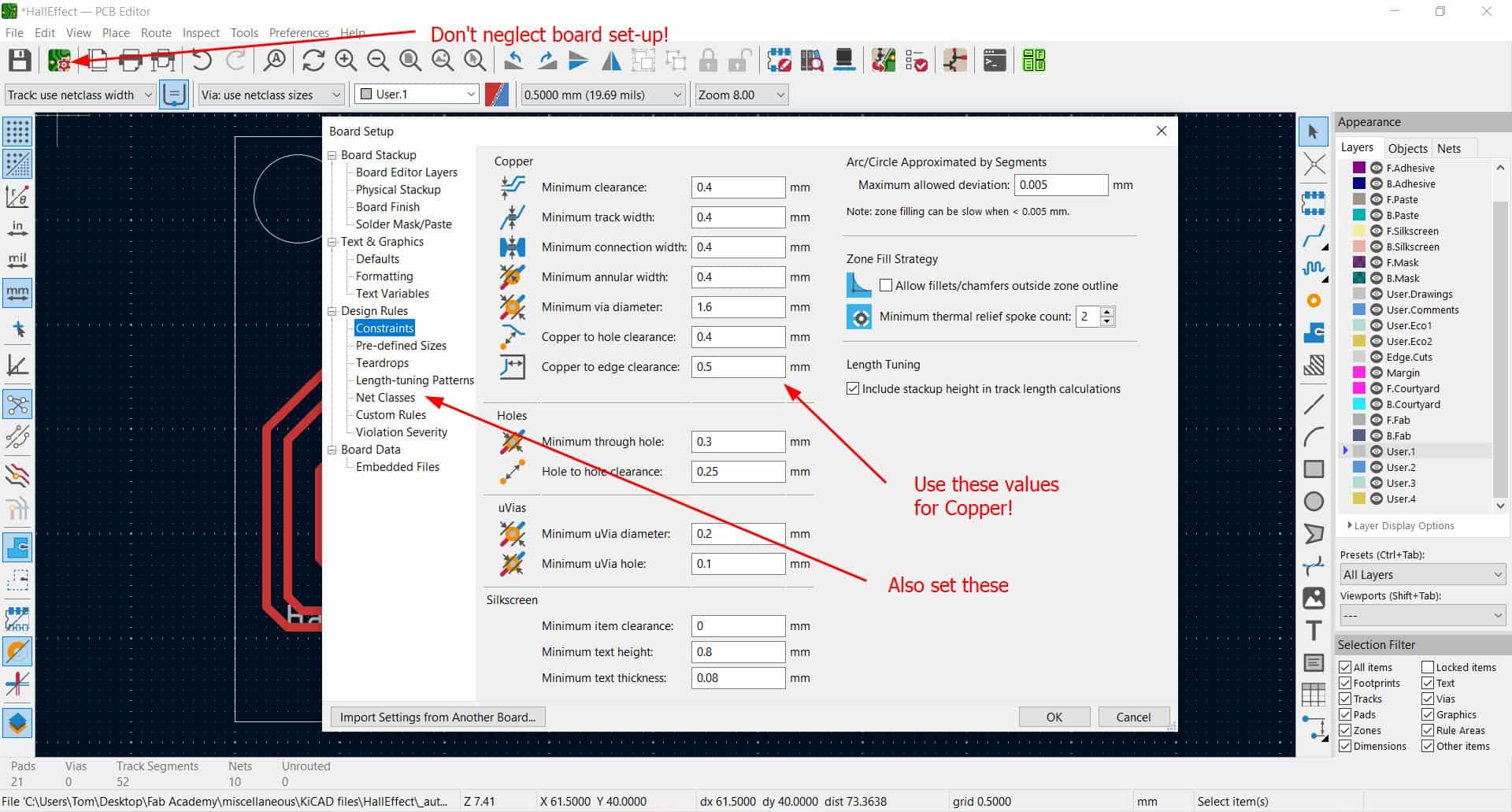
Also "net classes" are required, as Mithun show in his documentation.
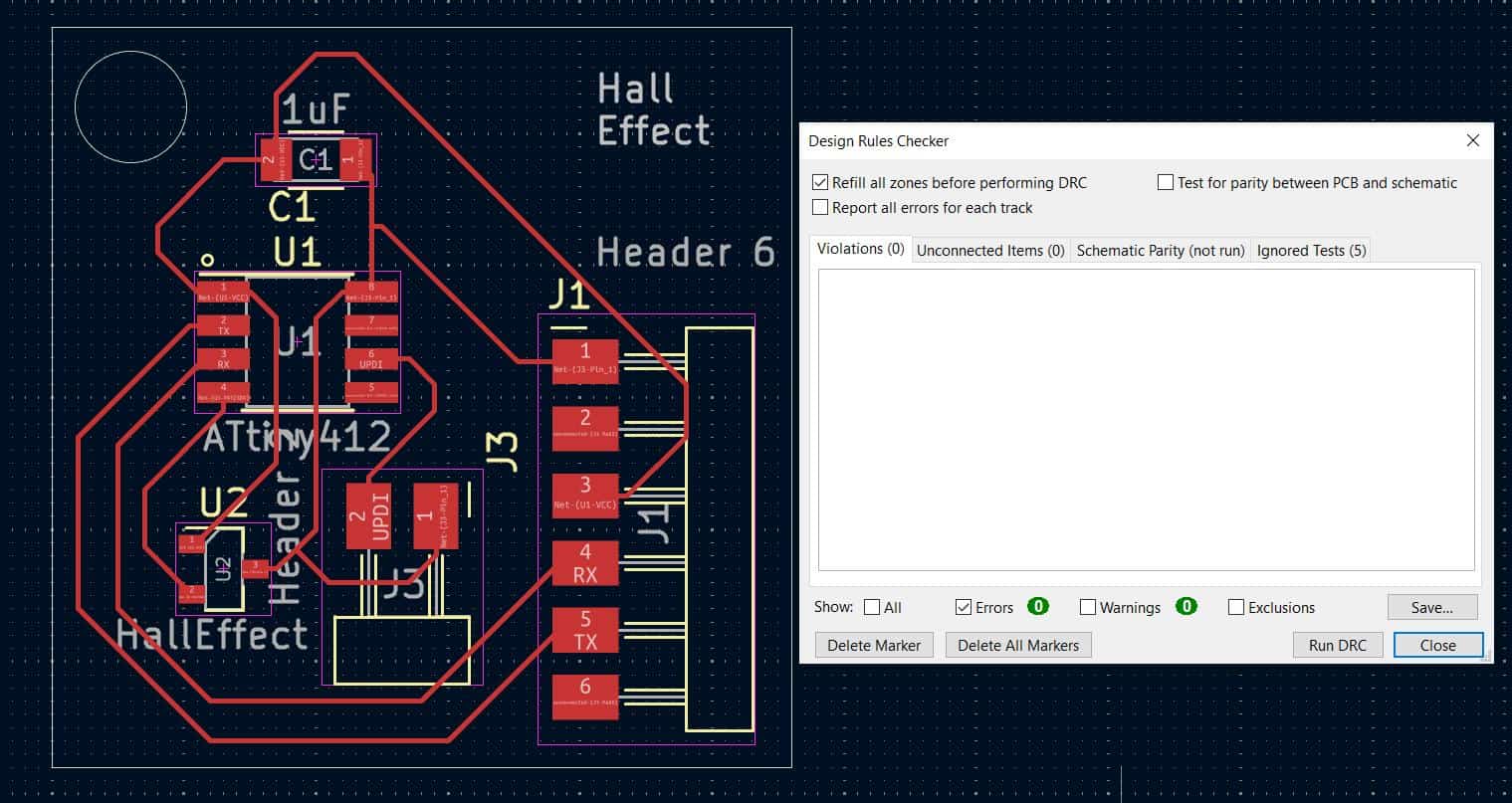
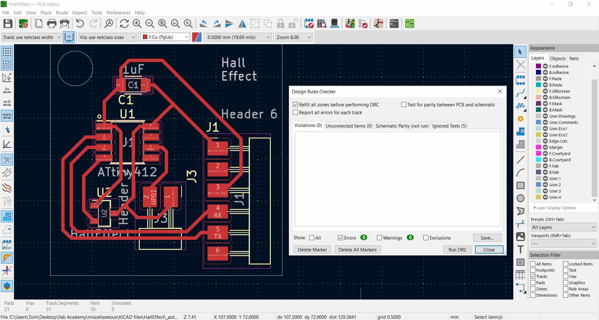
Here is the board again, after passing the DRC perfectly:
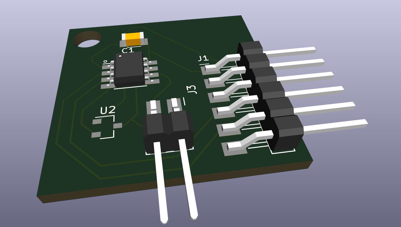
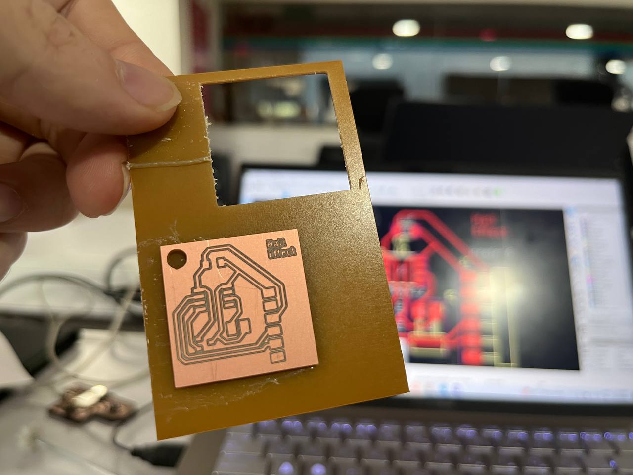
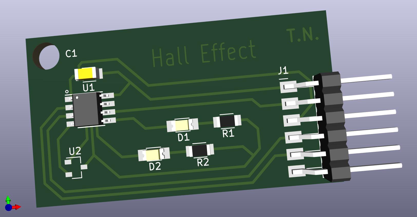
Finally, the 3D viewer and actual board.
Analysis: Saheen raised his eyebrow, specifically at the two pin header. Here's the issue: 1) The two pin header in my design is not in the right position - it should be closer to the edge to allow a programmer to be connected. 2) The two pin header is also not even required in my case. Neil had the two pin header for programming, but here we are using a marvelous UPDI/FTDI board developed by Saheen. This means that we can both program and read from one programmer and do not need two as does Neil. Moral of the story: don't blindly copy!
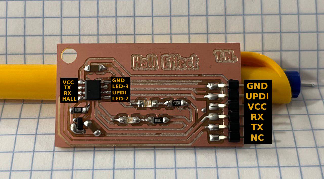
NEW Board with Hall Effect Sensor!
Given the aforementioned difficulties, it is necessary to make another board to test the Hall Effect Sensor. This new version is more coherently designed and lookes sexier as well. In the following 3 pictures show the Schematic, PCB Design, and 3D rendering. Engraved without difficulty on the Rolland MDX. Soldering was also fine, please refer to previous weeks' documentation.
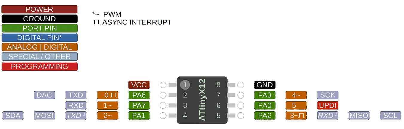
Getting started Programming ATTiny412 with UPDI
Let's get started with the ATtiny 412 Pinout:
The big idea is that we will use an additional board called a programmer to program the ATtiny in the Arduino IDE. I started by reading some documentation from Adrien and Saheen as well as watching a tutorial on YouTube.
The first issue to program is setting it up. As mentioned, we'll use the Arduino IDE but we need to configure for the ATTiny and some other settings.
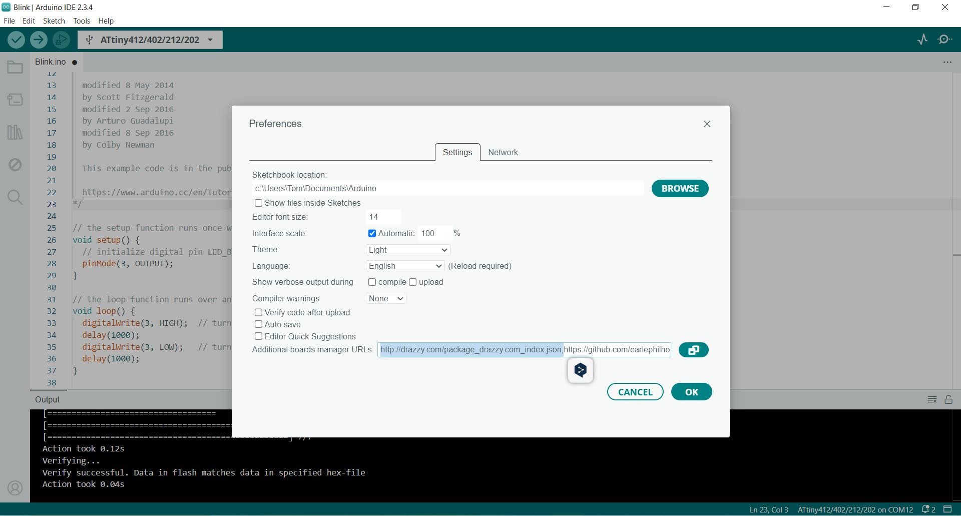
1. Under File -> Preferences, copy "http://drazzy.com/package_drazzy.com_index.json" into the required space.
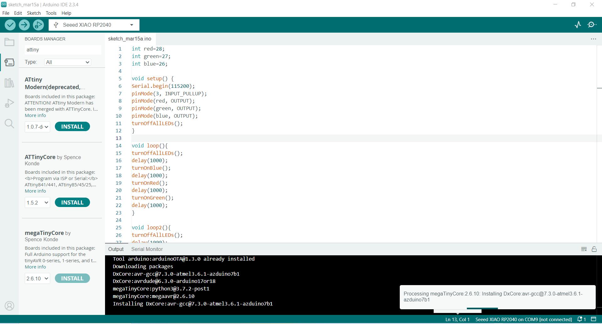
2. Now navigate to Boards manager and install "megaTinycore"
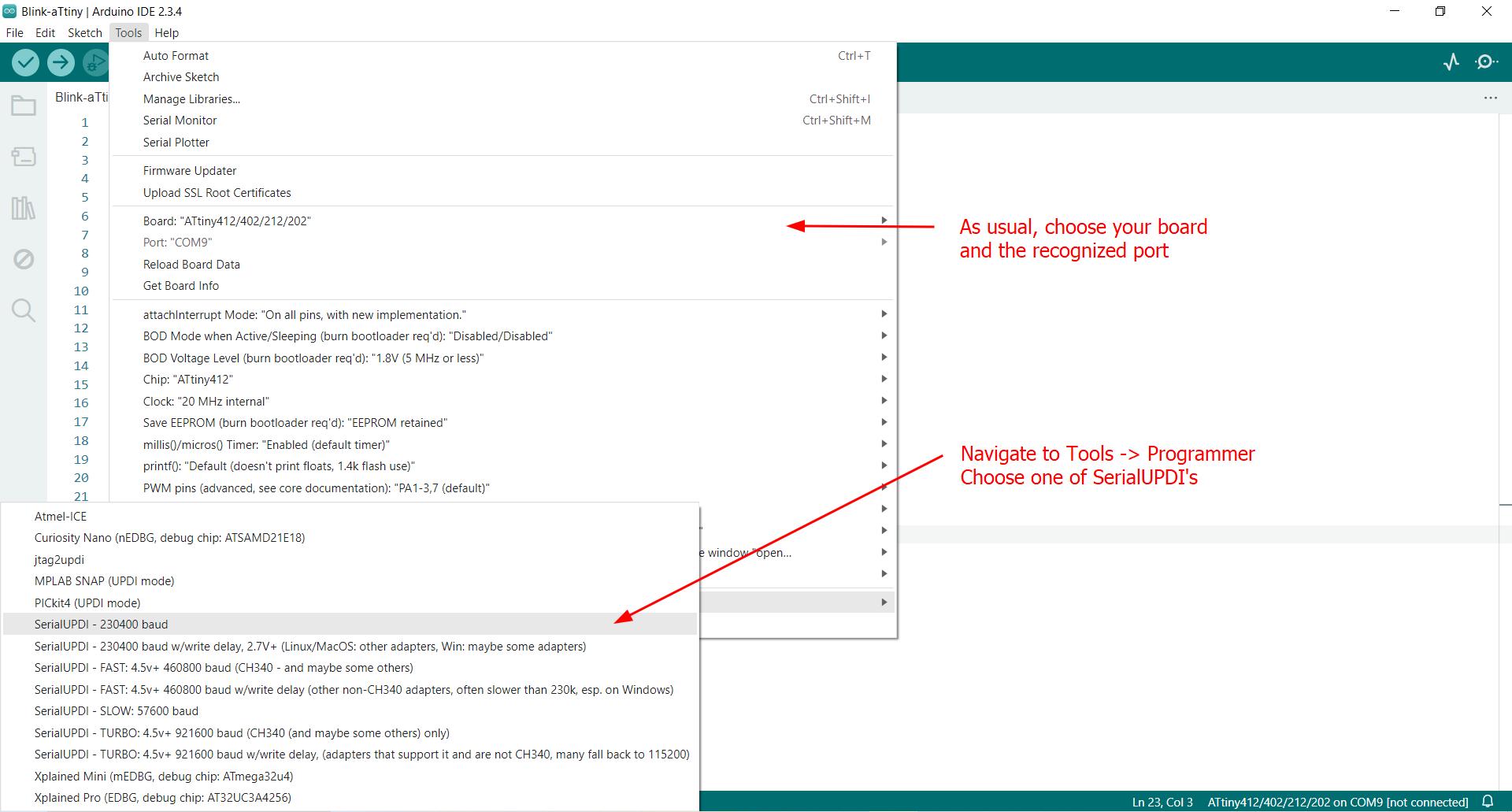
3. Finally choose your board, port and programmer.
If you don't know your programmer, you can choose to either be a genius or ask Saheen!
Now to test with the very simple blink program, we just need to change that pin to 3... and it works.
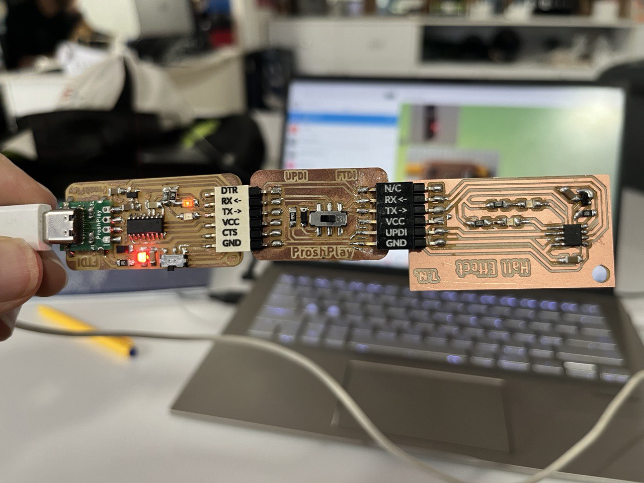
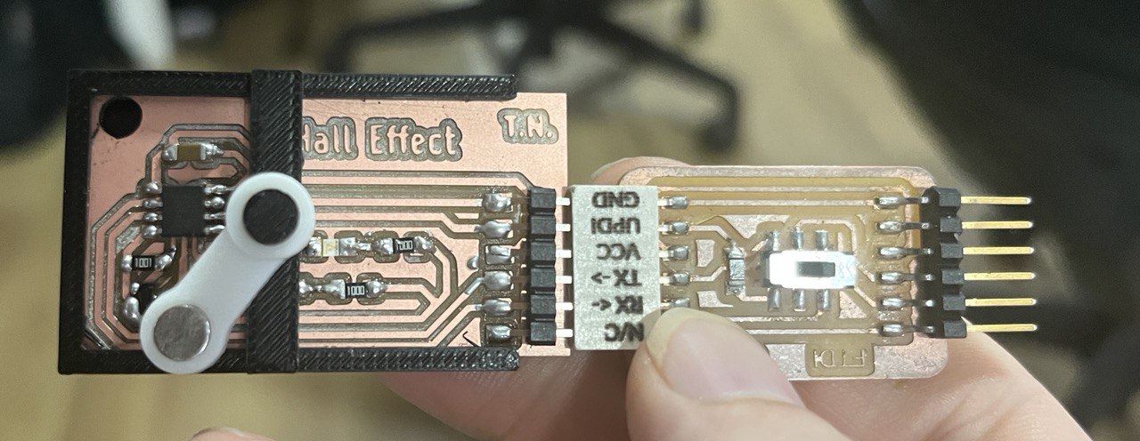
Notes on the programming set-up and Saheen's board: There are actually 2 boards from Saheen here, together allowing for both communication and programming, with the modes being toggled by the switch in the middle board, which changes the mode between UPDI (programming) and FTDI (communication). It's a little tricky the first time because to download the program from the Arduino IDE, the switch must be at UPDI, whereas to start the serial communication and print the sensor value to the serial monitor, FTDI (for communication) must be engaged.
Inconsistent Readings
We made a very simple program which will simply print 'magnet' to the serial monitor if a magnetic field is detected by the Hall Sensor. Here's that initial program, essentially digitalRead example already in Arduino IDE.
void setup() {
Serial.begin(9600); //start serial communication
}
void loop() {
int sensorValue = digitalRead(2); //read sensor value, save as 'sensorValue'
if (sensorValue==0){
Serial.print("magnet"); //prints 'magnet' to serial monitor if magnet detected
}
Serial.println(sensorValue); //also prints a value 0 if magnet detected, otherwise 1
delay(10);
}
But unfortunately it was not consistent, since this Hall Effect sensor is old and needs to be set up in another way as shown by Nihal:
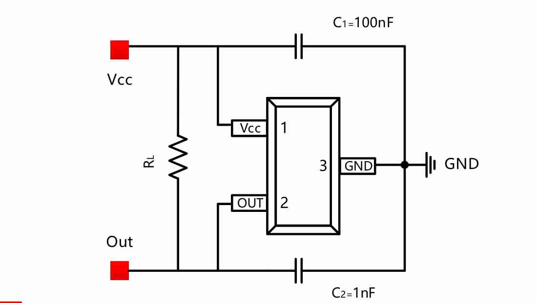
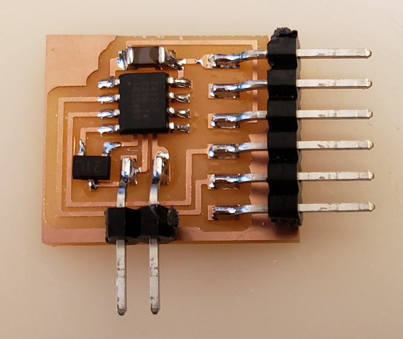
Instead of reprinting the board, Saheen suggested to add an additional resistor and capacitor to this board. The added resistor and capacitor are in the lower left corner of the board. The resistor connects the output and vcc lines, while the capacitor makes a connection between the output and ground. Here it is done:
Now with the modified board the program is working nicely with sensor value reacting to magnet presence as can be seen on the Serial Monitor on the computer screen when the magnet comes close.
More testing / programming of the Hall Effect
Wanted to continue programming and keep track of the count of magnet interactions. Of course if a magnet approaches the sensor, and if delay is small like 10ms, it's very easy to count the one magnet interaction multiple times. We avoid that in this code:
int oldSensVal = 1; //initialize sensor value
int count = 0; //initialize count of magnet passes
void setup() {
Serial.begin(9600); //start serial communication
}
void loop() {
int sensorValue = digitalRead(2); //read sensor value, save as 'sensorValue'
if (sensorValue==0){ //if sensor value is 0, i.e. detects magnet
Serial.print("magnet"); //..print 'magnet'
if (sensorValue!=oldSensVal){ //if the sensor value has just changed
count++; //count that as an additional count for magnet passed
}
}
else{ //otherwise..
Serial.print(sensorValue); //print the sensor Value (0 or 1)
}
Serial.print("-");
Serial.println(count); //display the total count of magnet passes
delay(10); //delay period (ms)
oldSensVal = sensorValue; //set currentvalue as the previous value
}
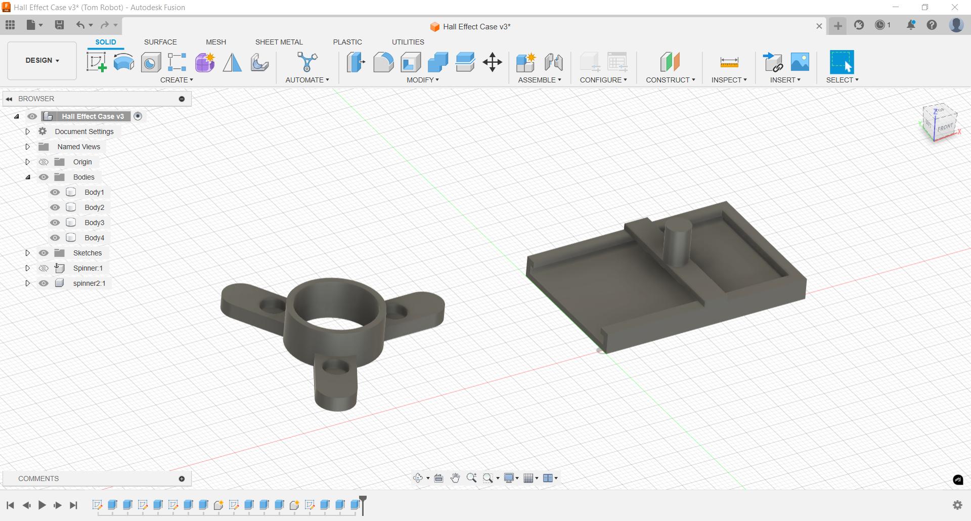
Designed and printed a board with an attachable spinner. The magnet goes in the spinner and it is spun around, and we can keep track of how many times it goes around with our program. Also added an LED blink when detected.
The magnet can be detected (as indicated by LED) even if the magnet is passing over the sensor really fast.
Further development idea of a blinking fidget spinner with a faster spin resulting in faster blink...
Printed it out, added a bearing, works better:
And here is a final even better video, showing the working program, note the Serial monitor in the background, printing "magnet" on each rotation as it detects the magnet: