Input Devices
week 10 assignment is to measure something by adding a sensor to a microcontroller board that I have designed and then read it
we are just back after the easter break.I come late this week following an advice from the LAB instructor I decided to do this input Devices week and the upcoming output Devices week in a single design.So I planed to make a tiny tachometer. my experience in electronics made it easier to design the final out put
Photo Transistor
It's a electronics Active component more like a Transistor but instead of a base pin it has a face which detect Infrared light.We can control the collector-emitter current flow by adjusting the IR light Intensity that we given on the front face of the transistor
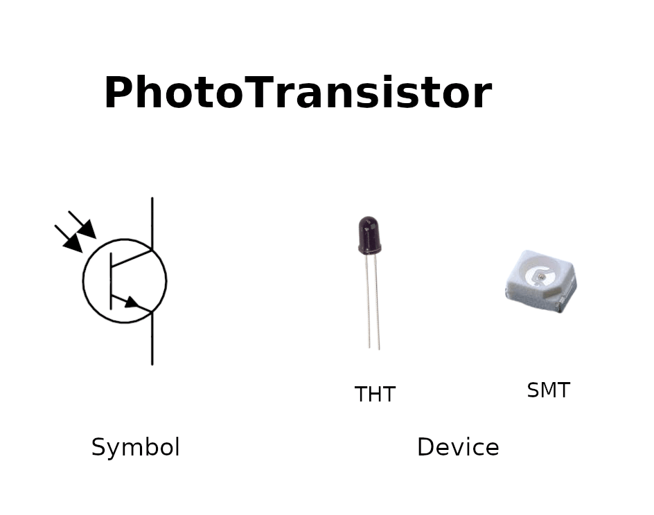
The above picture shows the symbolic representation of an NPN type PhotoTransistor and also the component photo of THT and SMT types.This available on both NPN and PNP type but NPN is the commonly used one
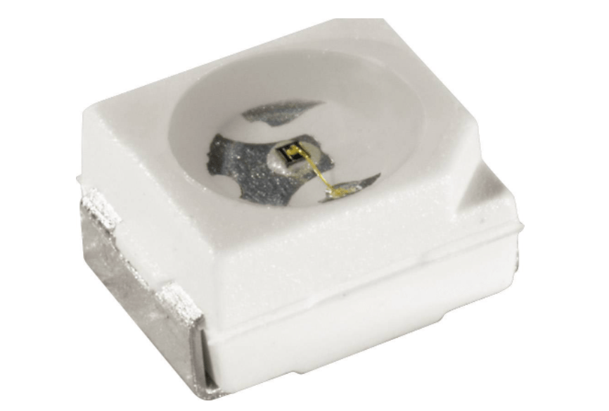
I'm using this Osram's photo diode (PLCC2 package size) which is available in our lab's Inventory.I found this Datasheet from conard.com
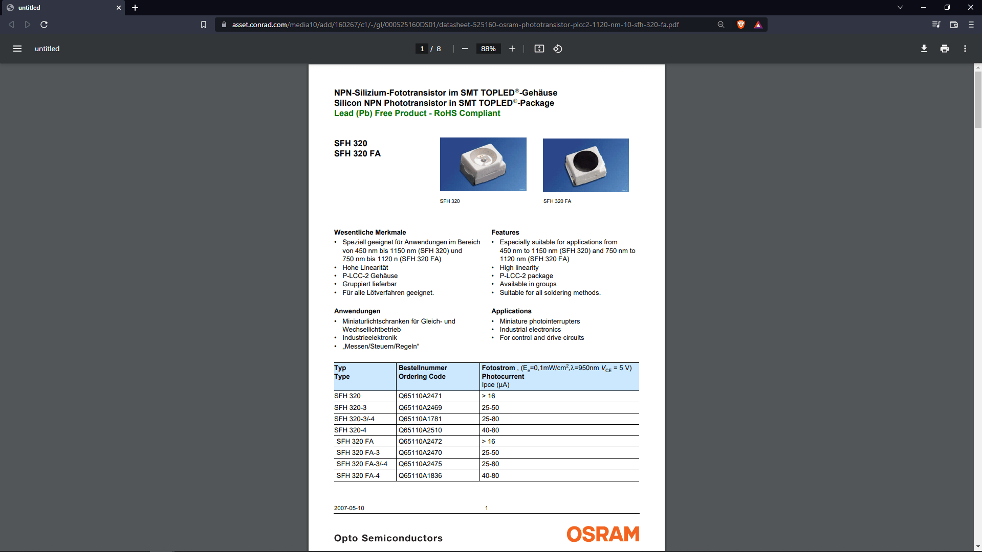
From the Datasheet I understand it comes 2 different design the one with IR filter and a normal one What I have doesn't have any IR filter.I got say that having IR filter is an advantage for the IR object detection and it can Avoid the visible light effects on it.
Infrared Detection circuit
For the Tachometer I need to design a Infrared Detection Circuit which include an IR LED and a PhotoTransistor then couple of resistors.
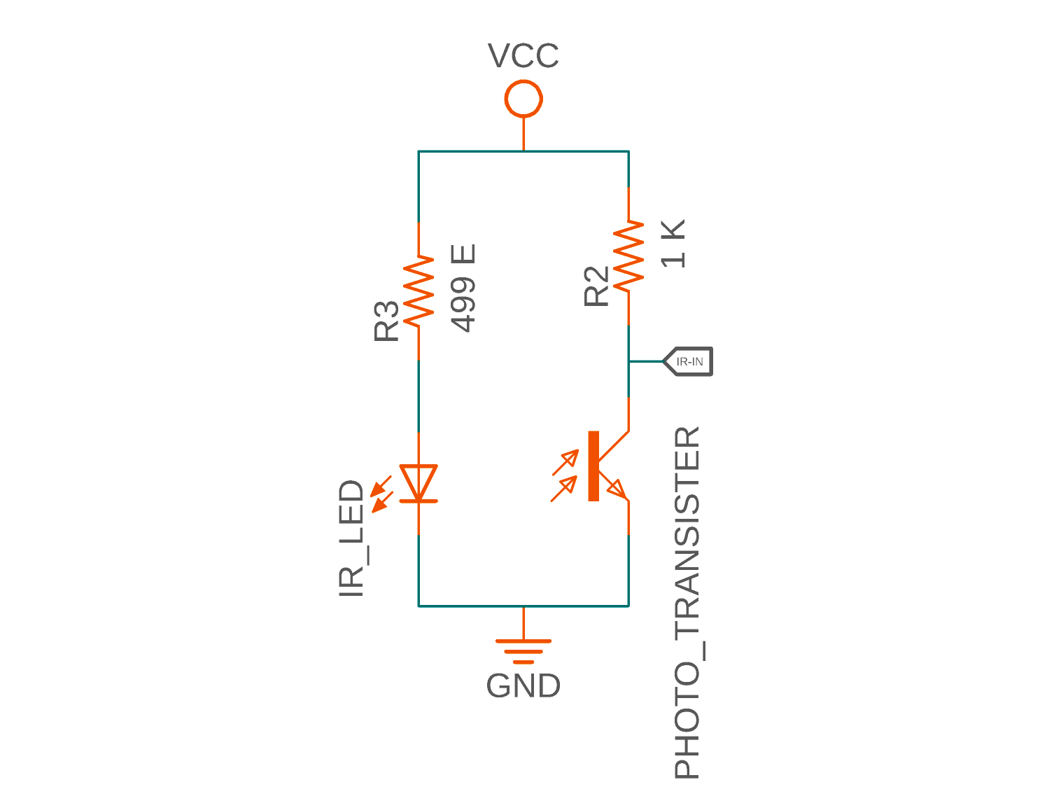
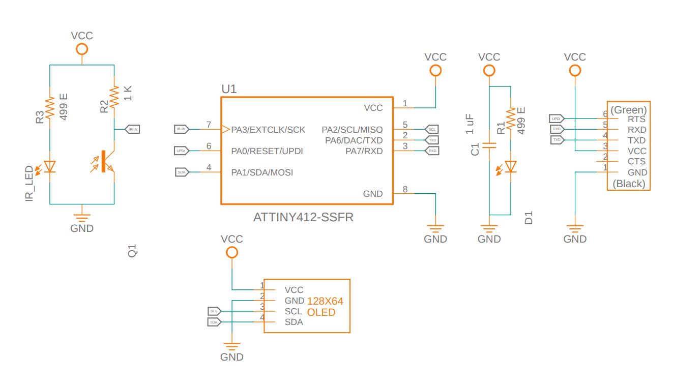
Her is the circuit that came up with fo the Ir detection part of the tachometer. An IR LED connected series with a resister of 4999 ohm in between the 5V and GND then the Photo transistor's emitter connected directly to the GND and the collector pulled up to the VCC with a 1 K ohm resister. The transistor works like a switch and the collector will connected to the microcontroller.
But from my previous experience on the IR object detection circuits I didn't need the circuit to get the Out put HIGH or LOW for my tachometer
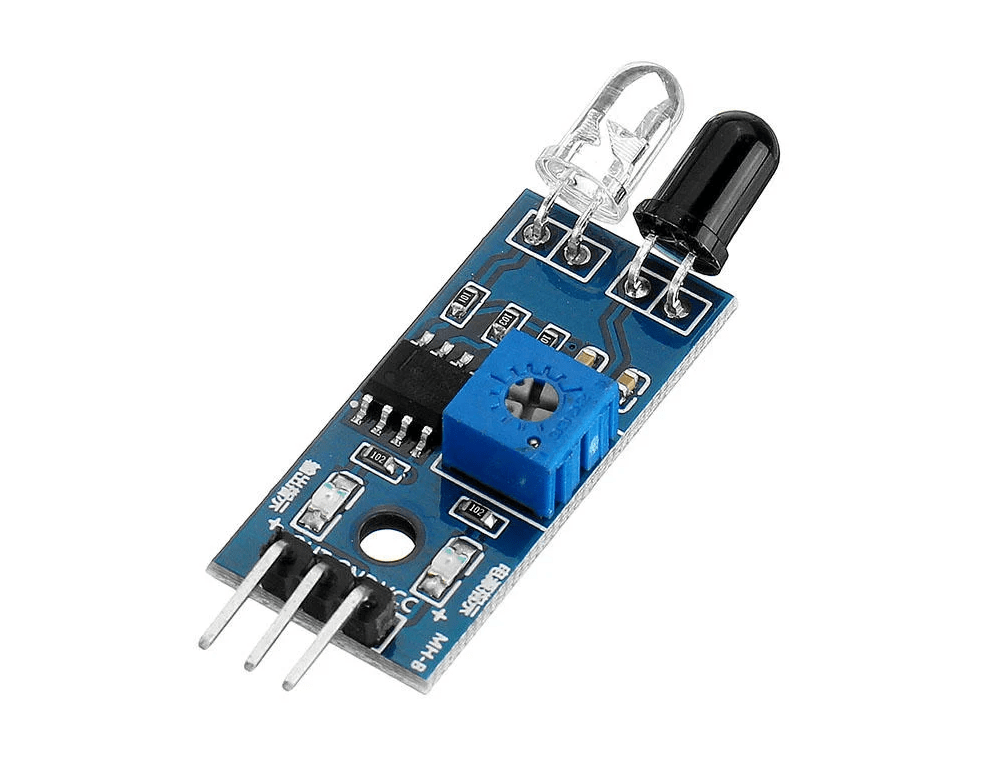
This is the module Commercial module used for object detection in hobby electronics projects in the module it has an IR LED and a IR photo diode(photo Transistor) additionally a small op amp circuit used to increase the sensitivity and accuracy by boosting the signal from the Receiver component.
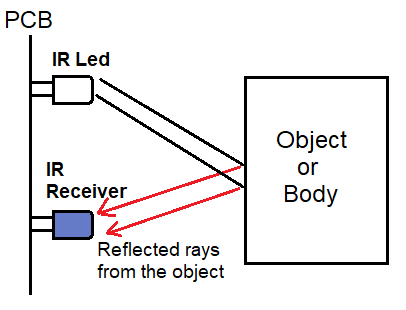
Here is the basic figure that show the working of the IR Object detection in easy way. The IR rays will reflect the surface (if it's not black) back to the IR sensor and the the photo transistor trigger by the rays then it will act as a transistor switch to give the signal to the microcontroller. In my design case the detection must be reflect only the white surface.
Attiny Tachometer
A Tachometer is a device to measure RPM of a mechanical rotating part or device.It has a sensor input and a microcontrollers and a out put device like a Display then a power source to power the circuit
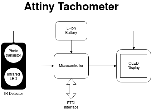
Based on my knowledge and some research I made this block diagram.for this week I only exploring the sensor part rest will complete in upcoming output Devices week.
From the diagram u can see I planned to use a photo PhotoTransistor and an IR LED to detect obstacle that reflect the light and then I also using a OLED Display for showing the RPM
Attiny412
During the Review of electronics design week Prof.Neil Strongly recommended to use the AVR 1 series New Attiny microcontroller in our assignments and circuits board because of the chip can do a lot more than the older versions of attiny series.Luckily we do have few of them in our Lab's inventory so I decided to try the new chips
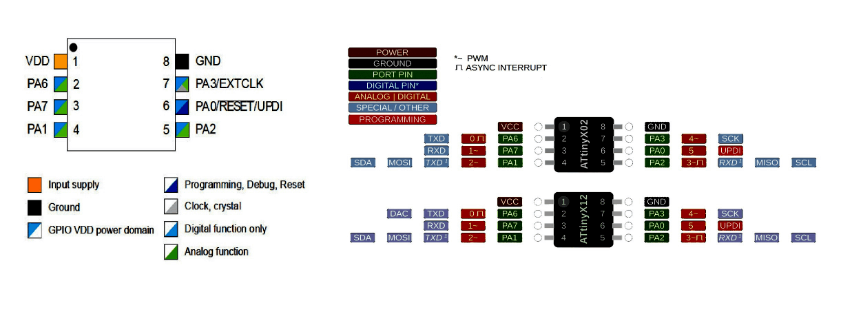
I chose the Attiny412 the smallest cheap Microcontroller available in our lab for doing the assignment as well as the Tachometer
- 20 MHZ Internal clock
- 4KB Flash Memory
- 128B SRAM
- Single Pin Unified Program Debug Interface (UPDI)
- 6 Programmable I/O Lines
- 10-bit 115ksps Analog to Digital Converter (ADC)
- 8-bit Digital to Analog Converter (DAC)
- External Interrupt on All General Purpose Pins
Specifications
The above specification's reference is taken from the Datasheet of the Attiny412.By doing some research across the fab documentations of previous students and Neil's FAB Academy tutorials I learn that the cheap is awesome as it is new.
- 6 X I/O (10 bit Analog/Digital) Pins (Including the UPDI pin)
- 4 X PWM OUTPUT pins
- 2 X ASYNC Interrupts
- 2 X UART Serial communication pin sets
- 2 X I2C Communication pin sets
- 1 X SPI Communication pin sets
Attiny412 Arduino Specifications
The arduino board manager named Megatinycore can be found in github this is the same guy who owns' the Attinycore board manager in github ,Spence Konde (aka Dr. Azzy). I got the information about the arduino Attiny 412 programing from adrian-torres's Embedded week. In additionally requires Python in our PC for part of the MegaTinycore board manager .
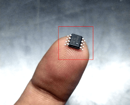
See how small the chip is actually in real. It's can fit in a finger tip!.The package of the chip is SOIC8 and not available in the Eagle FAB library for PCB design.also the soldering will be bit tough because of the size But I think I can handle that.
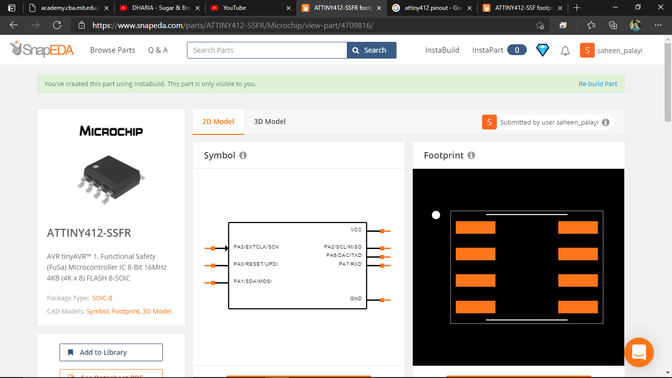
For downloading the library of the foot print and the symbol fo the Attiny412 I logged in to the snapeda.com and found the foot print I wanted but the library doesn't have any symbol with it so I used the Instabuild feature of the snap eda to build my own Attiny412 symbol to the foot print then downloaded for fusion 360 electronics CAD.
PCB Designing in Fusion
I designed the PCB in the Fusion 360 according to the plan from the block diagram. It was very easy to build wire everything and convert into a PCB wit the New Attiny412 chip.
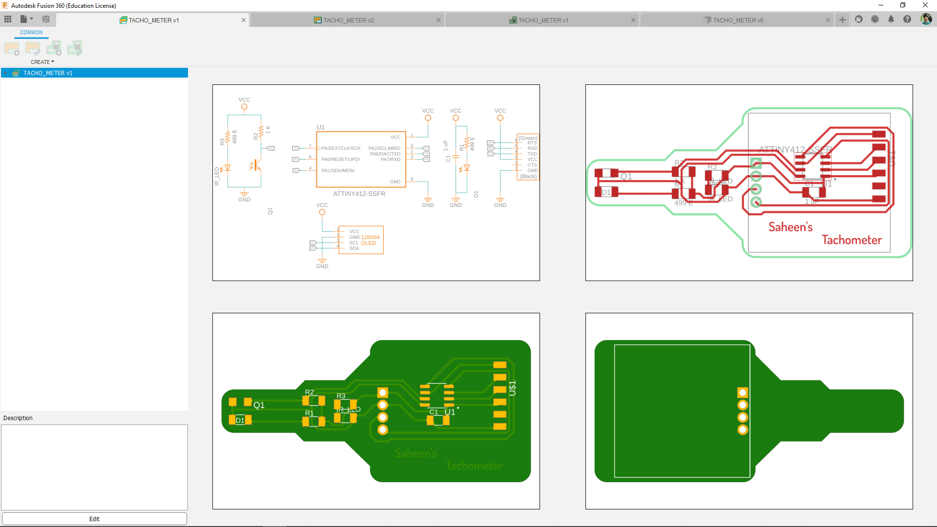
The microcontroller only required a power filter capacitor as minimal circuit. I'm aslso added the OLED solder pin-outs that can use later in the upcoming OUTPUT week.
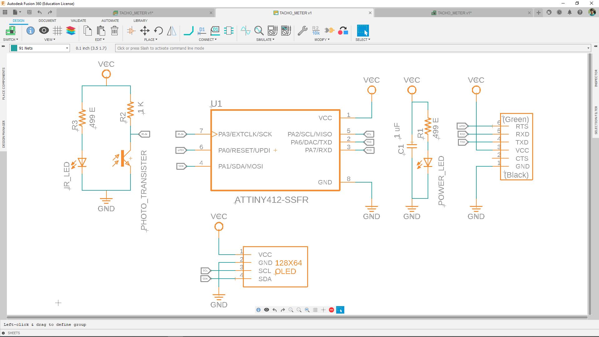
Also added a FTDI Connecter to the Atiny412 for communicating through serial monitor from the computer and one of the FTDI PIN (RTS) used as UPDI.For "Why I did like this" see my UPDI doc section to know more.
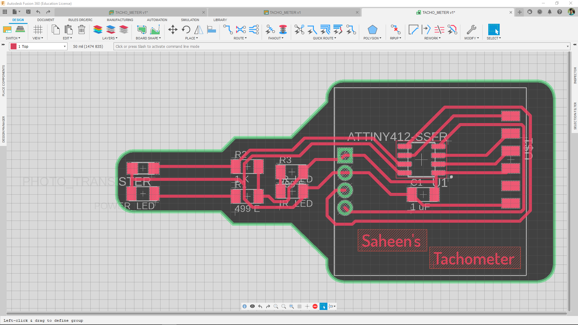
Here is the Design of the PCB that I wanted to be mill out . I gave a unique shape to it so it can feel like a measuring device with a probe(sensor) on at the end.the Ir Detection part placed at the end and the OLED comes in other side.
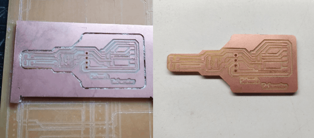
I exported the PCB necessary files(traces and outline monochrome png files) for milling then milled out the board on the Modella Mdx-20 milling machine.
.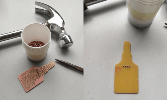
I used the through hole rivets for Inserting the OLED display like a plug and play device because the OLED display is bit costly and only have few in the lab so this way I can test the circuits works or not if it is works then will permanently solder the OLED on it.
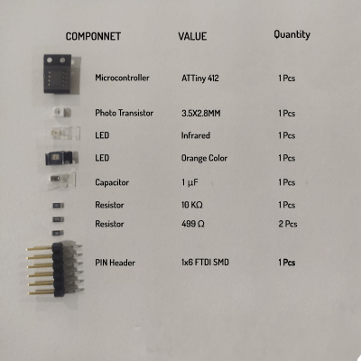
These are the components I collected from the inventory for soldering the tachometer board.And I did not added the OLED display module for now I think I will do that during my out put week.
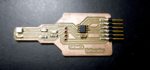
Then I beautifully soldered everything in place as I designed. The Attiny 412 wasn't that tough to solder as I thought before and the soldering job was too easy because of only few components used in this design.
UPDI Programer
From the exploration fo the new AVR series 1 microcontrollers and programing I understand that it is using a new protocol called UPDI for programing the Microcontrollers over the past ISP programers.Which means I have to make a new programer to program the Attiny412 That I'm using in this assignment.
From prof.Neil's tutorial I understand that I can create dimple FTDI to UPDI converter for programing the Attiny412 via PI-UPDI technique.
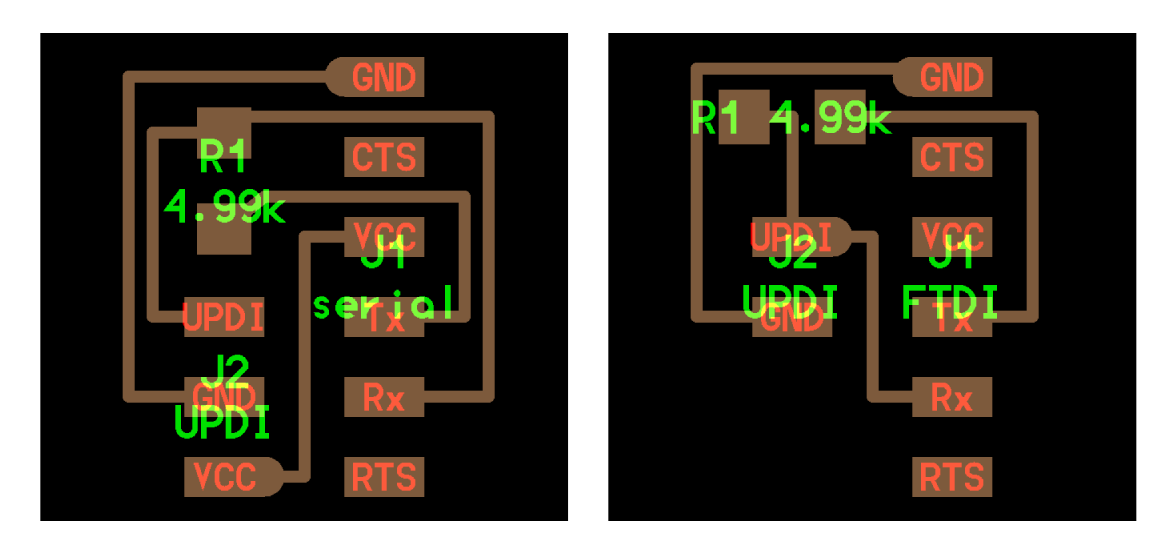
During the class I've seen this board that Neil explaining to us and turns out it just need a resistor and some connectors to create the programer. from the available board files I can either create a 2 pin UPDI or 3 PIN UPDI converter. Here one has VCC and other one only has GND and UPDI.
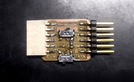
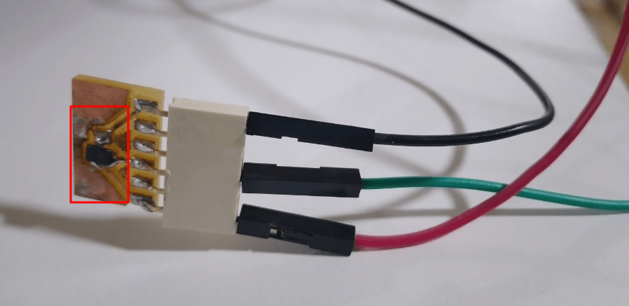
This is the FTDI/UPDI converter that I designed and made in FabLab.You can see as a part of the optimization and some thinking I came up with an idea to fabricate the both FTDI and UPDI switchable converter for the simplicity of the programing and circuit designing.but this isn't enough and I have to improve my design
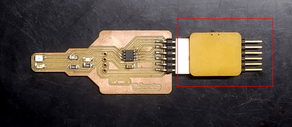
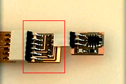
Here is the image shows how the UPDI/FTDI board attached in use. The FTDI cable will attach through the 6 pin male heder pins of the UPDI/FTDI board.
Programing with Arduino
The arduino Environment and it's community is more advanced nowadays and supports lots of open source hardwares and microcontrollers in it's arduino IDE. From adrian's documentations I learn that how to add the AVR new series attiny chip's board manger into the arduino IDE.
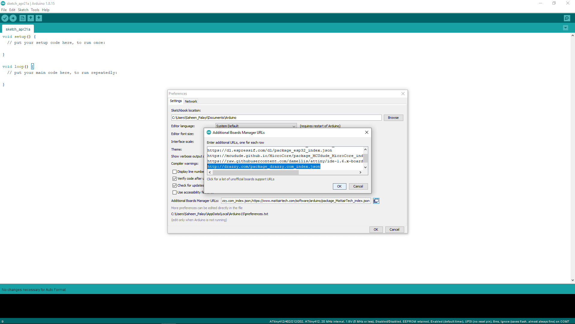
I added the json code shows below in the arduino >> preference >> Additional manager URLs .For the installation I reffered this documentation from Spence Konde (aka Dr. Azzy).
http://drazzy.com/package_drazzy.com_index.jsonThe megaTinyCore is awesome community contribution for the hardware developer this same guy also written many other tools and board managers as open source.
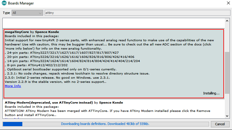
Then I opened the board manager by clinking Tools>> Board >> Board manager on arduino IDE then after the index loaded I searched for MegaTinycore and clicked the install button for adding the board manager to my Arduino IDE.
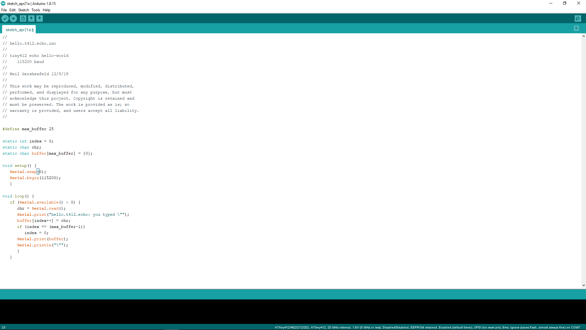
For the testing the Attiny412 tachometer board I downloaded Neil's hello.t412.echo.ino code from fabacademy's embedded_programming class page.Then I edited the 'Serial.swap(1); to Serial.swap(0); because the attiny412 has two UART RX ,TX PORTS I was using the first one in my design where in Neil's program it was the second one. If we didn't define the swap() function the arduino Serial library also select the first one as default.
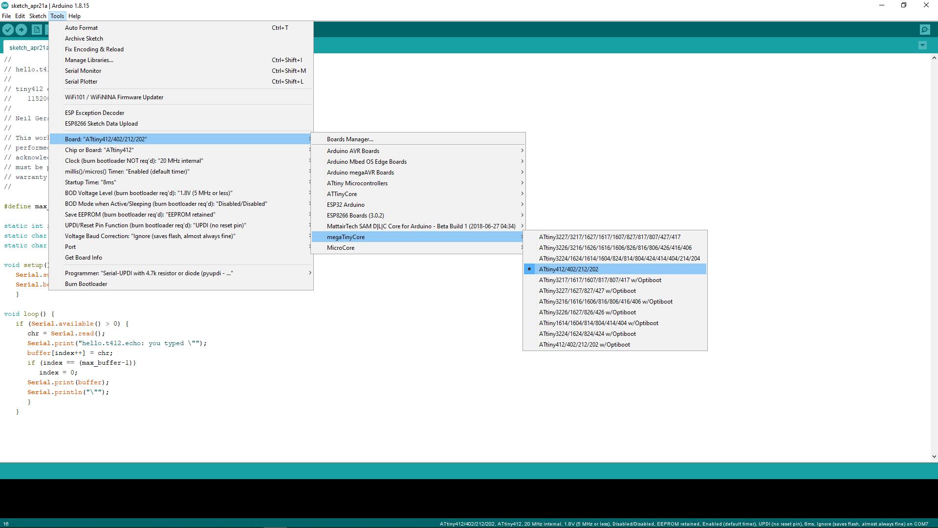
As next step I selected the Board via Tools >> Board >> megaTinyCore >> Attiny412/402/212/202 there are many other different board available for other Attiny chips according to the pin numbers and flash memmory size.
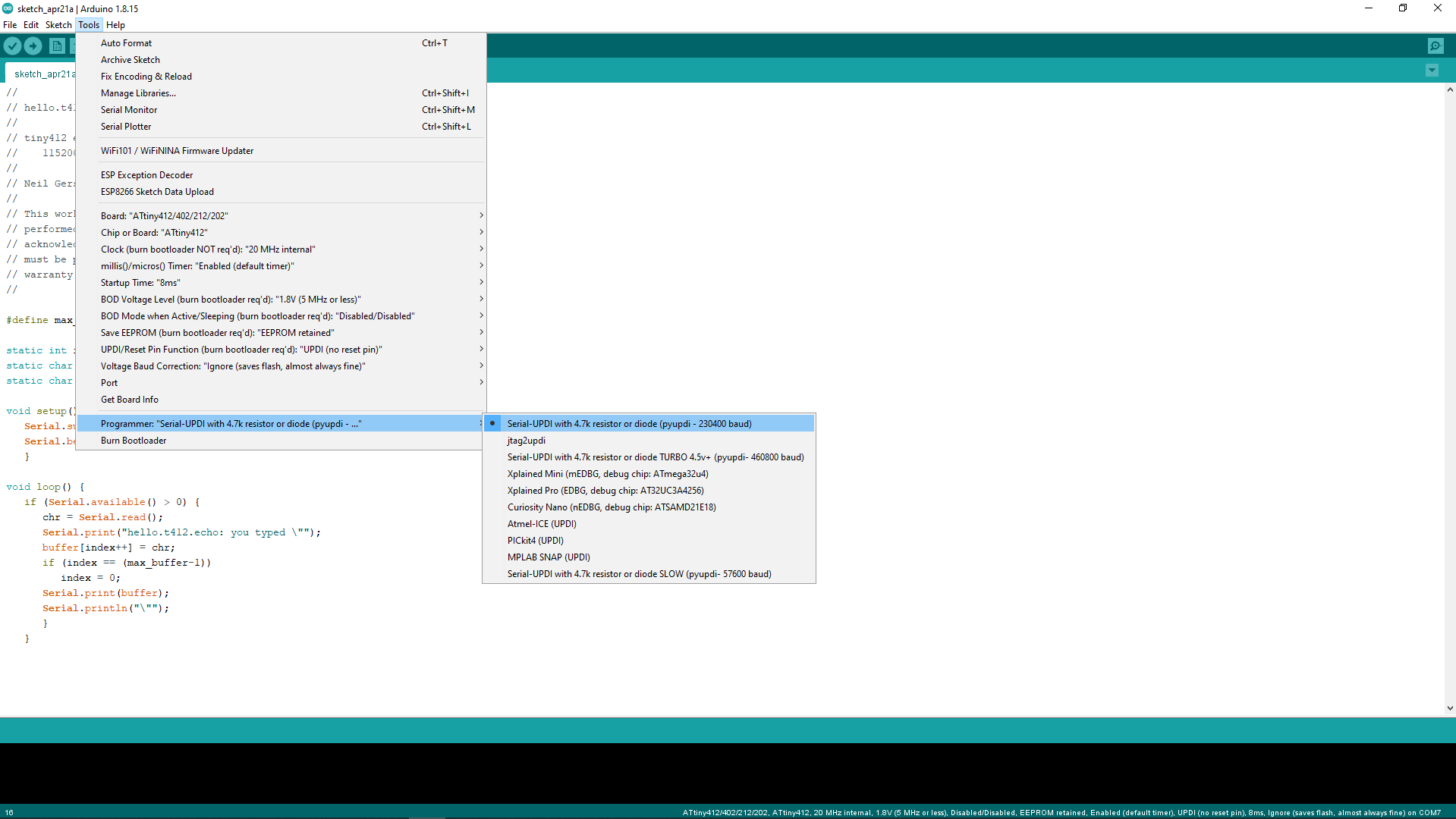
Then I selected the Programer as "Serial-UPDI with 4.7k resistor or diode (pyupdi - 230400 baud)" from the available programer list. The other UPDI also works, those are available for different programing speeds and voltage levels.
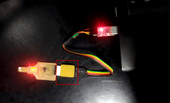
here is the programing setup I pluged to my computer for uploading the code. after I plugged the board I selected the COM port in the Tools sections of the arduino then clicked upload button.
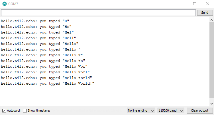
The Uploading was successful then after some connection rechecking I got the board running the echo hello world.
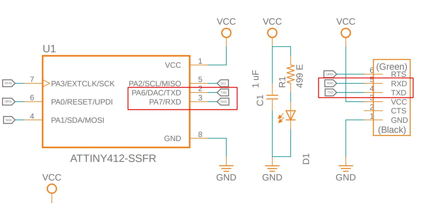
Here is what I found while the connection re-check ,I did an error in the schematic the RX,TX of the Attiny412 and the FTDI connector must be like TX of FTDI Connector --> RX of the Attiny412 and also RX of the FTDI connector <-- TX of the Attiny 412.
- (FTDI)Rx <-- TX(Attiny412)
- (FTDI)TX --> RX(Attiny412)
I did the same mistake while the electronics design week but Did not recognized because the Attiny84 chip that I used in the Electronics design week doesn't have any Hardware UART
I wrote a program in arduino IDE that read the sensor output through pin 4 of the attiny412 and transmit to the computer over serial UART port to print on the serial monitor.Then I uploaded to My board and ran the test by using a white box as an obstacle.The program do print both analog and Digital values from the sensor, That you can see in the above video the defualt digital output is '1' (HIGH) and the maximuma analog value obtined is near 900
CODE :-
                // Photo_Transsitor_Reading.ino
                //
                // tiny412 Reading Photo Transistor OUTPUT
                //    115200 baud
                //
                // Saheen Palayi 23/4/22
                //
                // This work may be reproduced, modified, distributed,
                // performed, and displayed for any purpose, but must
                // acknowledge this project. Copyright is retained and
                // must be preserved. The work is provided as is; no
                // warranty is provided, and users accept all liability.
                //

                #define max_buffer 25

                static int index = 0;
                static char chr;
                static char buffer[max_buffer] = {0};


                void setup() {
                  pinMode(4, INPUT); // The 4 th pin set as input
                  Serial.swap(0);   // swap set to '0' for selecting the first UART port of attiny412
                  Serial.begin(115200); // Setting BAUD rate 115200
                }

                void loop() {

                    Serial.print("Digital Value: ");   // printing "Digital Value:" on the serial monitor
                    Serial.print(digitalRead(4));      //reading and printing the digiratal value from 4 th pin on serial monitor
                    Serial.print("\t Analog Value: "); // printing "Analog Value:" on the serial monitor
                    Serial.println(analogRead(4));    //reading and printing the Analog value from 4 th pin on serial monitor
                  delay(1000);                       // delay for waiting 1 second

                }
The out put analog values varies when the obstacle getting closure and the digital value changes to '0' (LOW).The lowest analog value I got is nearly 150 the analog value ranges from 0 - 1023 as per the voltage difference between 0-5V.
Then I did test the same code with a light source to see the reaction of the photo transistor wit the Intensity of the light.So this photo transistor also can be used as a light intensity sensor .This is actually a problem to my tachometer project because it may trigger with bright light with higher Intensity like the Sun light. There are two methods available to avoid this one of them to use an IR filtered Phototransistor.
But we dont have that IR filtered Phototransistor the other way to do some trick to the code and IR emitting LED source.I've seen this while Neil explaining to us during the Input Devices week class.
As next I wrote an Interrupt program as a test to my final tachometer code. This code is simply print "Hello World" on the serial monitor in every 1 second and then it will print "Detected" when ever there is an Obstacle detection happening.
CODE :-
                        // Photo_Transister_Intrupt.ino
                        //
                        // tiny412 Photo_Transister Intrupt Detection
                        //    115200 baud
                        //
                        // Saheen Palayi 23/4/22
                        //
                        // This work may be reproduced, modified, distributed,
                        // performed, and displayed for any purpose, but must
                        // acknowledge this project. Copyright is retained and
                        // must be preserved. The work is provided as is; no
                        // warranty is provided, and users accept all liability.
                        //


                        void setup() {
                            pinMode(4, INPUT); // The 4 th pin set as input
                          Serial.swap(0);   // swap set to '0' for selecting the first UART port of attiny412
                          Serial.begin(115200); // Setting BAUD rate 115200

                          attachInterrupt(digitalPinToInterrupt(4), isr, FALLING); // attaching the pin 4 as intrupt when falling edge detected then execute the 'isr()' function
                        }

                        void loop() {
                          delay(1000);  // delay for waiting 1 second
                          Serial.println("hello_world"); // printing "hello_world" on the serial monitor

                        }
                        void isr() // this function will execute when intrupt the main loop
                        {
                          Serial.println("Detected"); // printing "Detected" on the serial monitor

                        }
Writing the Tachometer Code
So I tested the sensor using the Arduino IDE and it's all working now I've to make an arduino code for reading the RPM in serial for now and then later will make a code for the OLED during the OUTPUT Week.
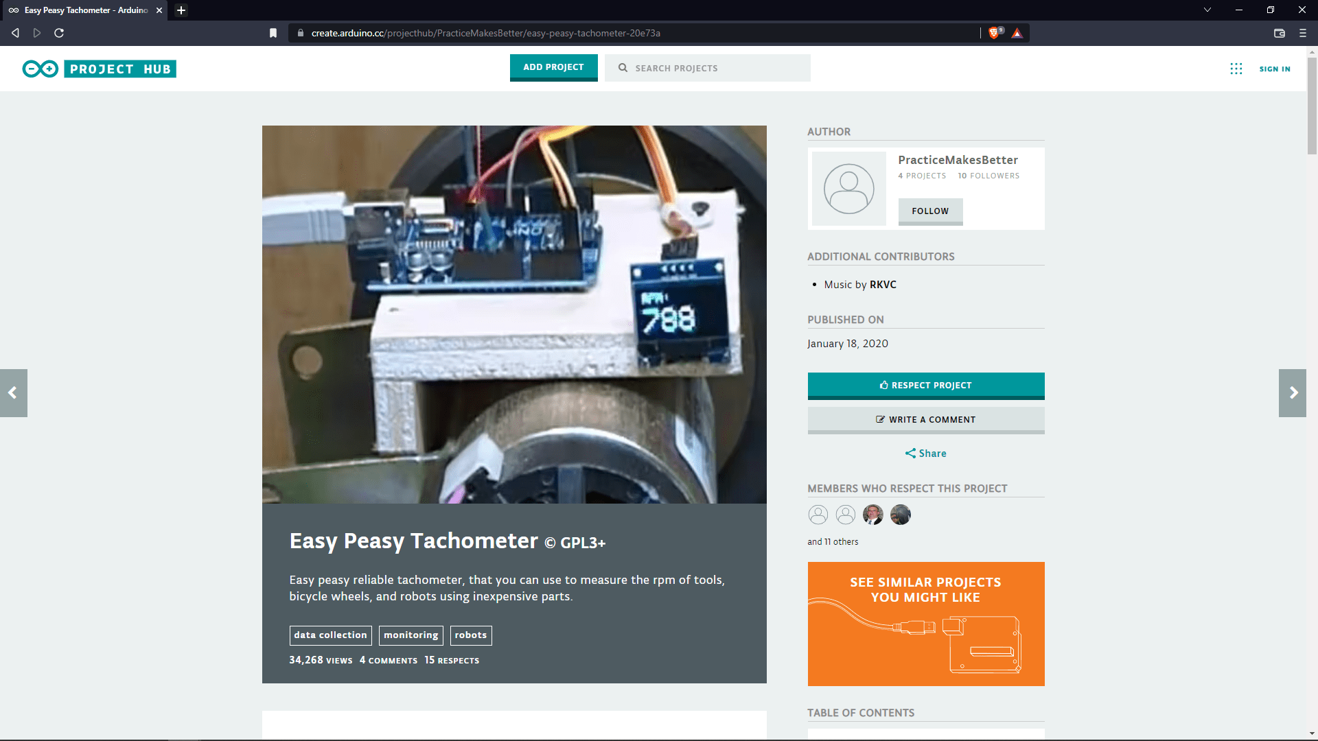
I found this project for referring how a simple Tachometer can be made using arduino.So just for the basics I explored the Easy Peasy Tachometer project from arduino.cc.

Using the reference project I've found, I made a serial program to calculate the RPM and print in the serial monitor
rpm=(revaluation/time)*60000 //calculates rpm Here is the formula that I used for the RPM calculation the 60000 represent 1 minutes in millisecond. and the revaluation is the counting value using the sensor.
CODE of the Attiny-tachometer :-
                                // Tachometer-serial.ino
                                //
                                // Tachometer-serial.ino
                                //    115200 baud
                                //
                                // Saheen Palayi 23/4/22
                                //
                                // This work may be reproduced, modified, distributed,
                                // performed, and displayed for any purpose, but must
                                // acknowledge this project. Copyright is retained and
                                // must be preserved. The work is provided as is; no
                                // warranty is provided, and users accept all liability.
                                //

                                #define sensorPin 4

                                float value = 0;
                                float rev = 0;
                                int rpm;
                                int oldtime = 0;
                                int time;

                                void setup() {
                                  pinMode(4, INPUT); // The 4 th pin set as input
                                  Serial.swap(0);   // swap set to '0' for selecting the first UART port of attiny412
                                  Serial.begin(115200); // Setting BAUD rate 115200

                                  attachInterrupt(digitalPinToInterrupt(sensorPin), isr, FALLING); // attaching the sensorPin as intrupt when falling edge detected then execute the 'isr()' function
                                }


                                void loop() {

                                  delay(1500);// 1.5 second delay

                                  detachInterrupt(digitalPinToInterrupt(sensorPin));           //detaches the interrupt while calculating

                                  //RPM calculations
                                  time = millis() - oldtime;    //finds the time
                                  rpm = (rev / time) * 60000;   //calculates rpm
                                  oldtime = millis();           //saves the current time
                                  rev = 0;

                                  //Printing the calculated RPMin serial

                                  Serial.print("RPM:");
                                  Serial.print(rpm);
                                  Serial.println(" rev/min");


                                  //attaching intrupt again to get the new value
                                  attachInterrupt(digitalPinToInterrupt(sensorPin), isr, FALLING);

                                }

                                // this function will execute when intrupt the main loop
                                void isr()
                                {
                                  rev++; // Incrumenting the revelution value

                                }
week 10 Group assignment is to probe an input device's analog levels and digital signals
Probing a sensor
According to the requirement of this week group assignment we need to connect a sensors output directly to the DSO to see the out put voltage level in live wave form and observe the waveform as per the sensor's performance.
Probing Hall Effect Sensor
Firstly we decide to probe a hall effect sensor because most of us used the sensor in the Input week and everyone very curious to know how it's work.
This break out is made by Hanani he was inspired from Adrian adrian-torres's Documentation to create break out boards for sensors to explore more input devices. This made our group project so easy because if we just give power to the break board it start perform no worry about other circuit impedance.
We powered 5V to the sensor using the bench power supply and then the output of the sensor connected to the Digital oscilloscope. and the we approSached a strong magnet to the sensor like in the above video gif.
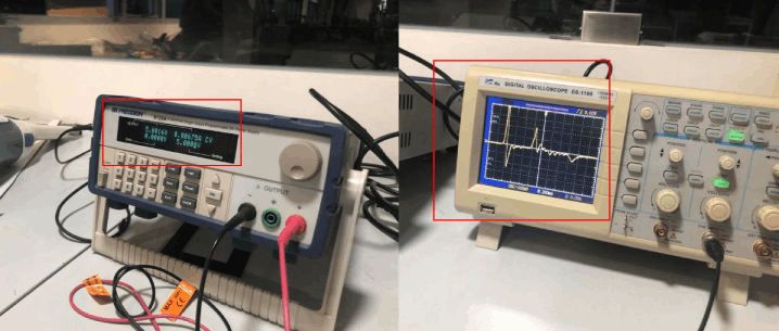
The current taken by the sensor during it's working at 5V constant ,It's about 0.00675 A only and the the output wave form we observe a straight line with out any operation.But if we approaches by the magnet we getting a high spike then we get a down spike also at the moment we retrieve the magnet from near by te sensor.
References
- Fab Academy Input Devices classes
- Fab Academy Embedded Programming classes
- Photo-transistor Datasheet
- Robui.in
- snapeda.com
- megaTinyCore Installation
Downloads
- PCb Design Files
- Arduino Programs