8. Electronics Production
- Group assignment
- Characterize the design rules for your in-house PCB production process: document the settings for your machine.
- Document the workflow for sending a PCB to a boardhouse
- Document your work to the group work page and reflect on your individual page what you learned
- Individual assignment
- Make and test a microcontroller development board that you designed
Group Assignment
Results can be found on the group assignment page of our lab.
Individual Assignment
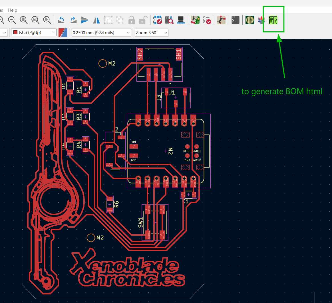
Downloading the Gerber2PNG plugin for KiCad
Fablab Kochi has a certain workflow for PCB fabrication. Here are the steps to start.
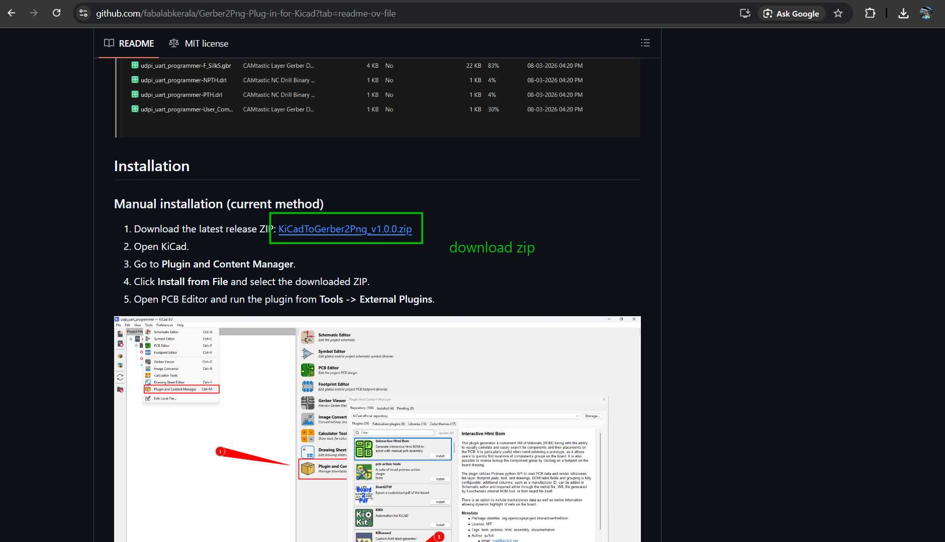
Download the ZIP files for the Gerber2PNG KiCad extension.
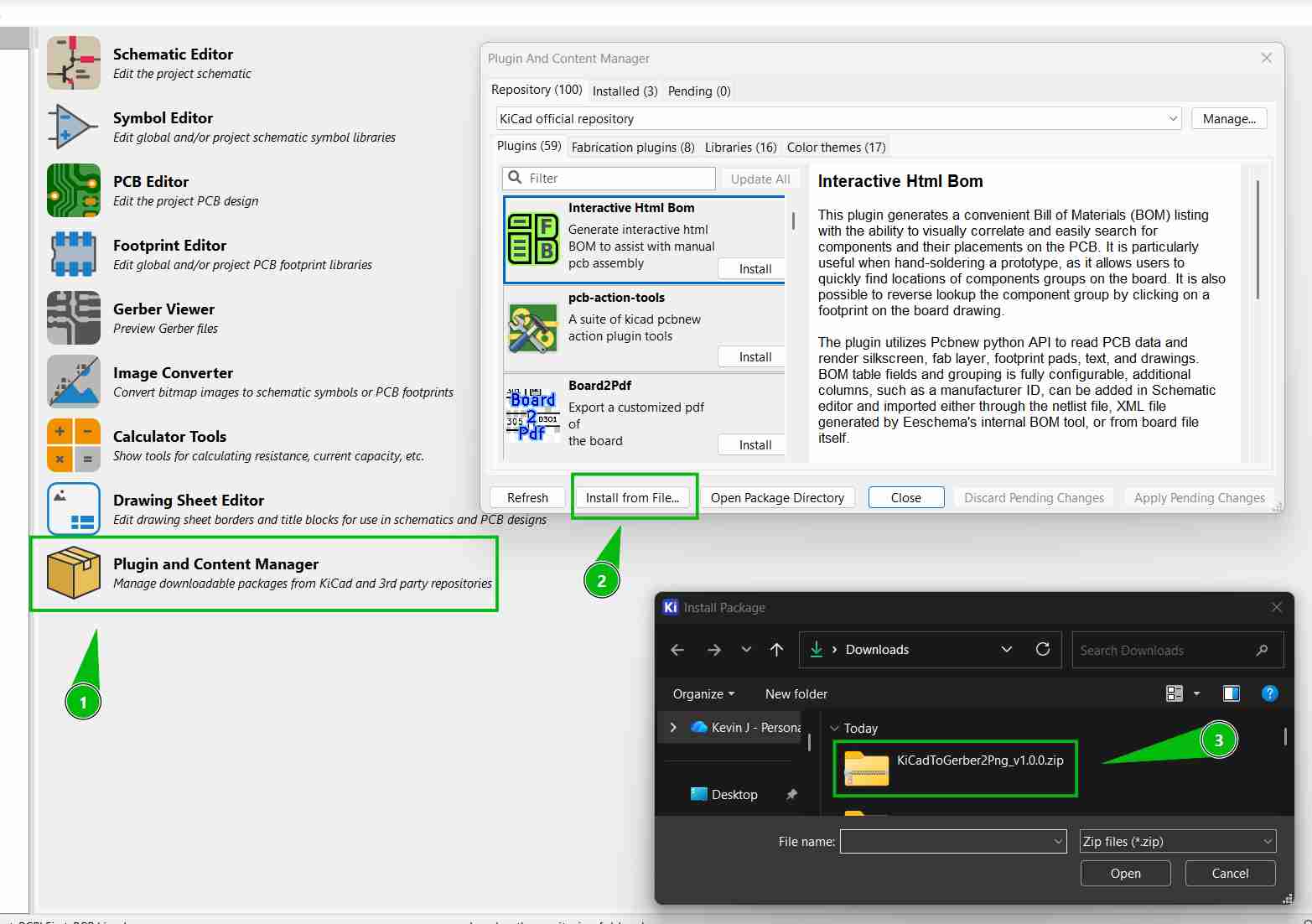
Click install from file and choose the ZIP file we downloaded.
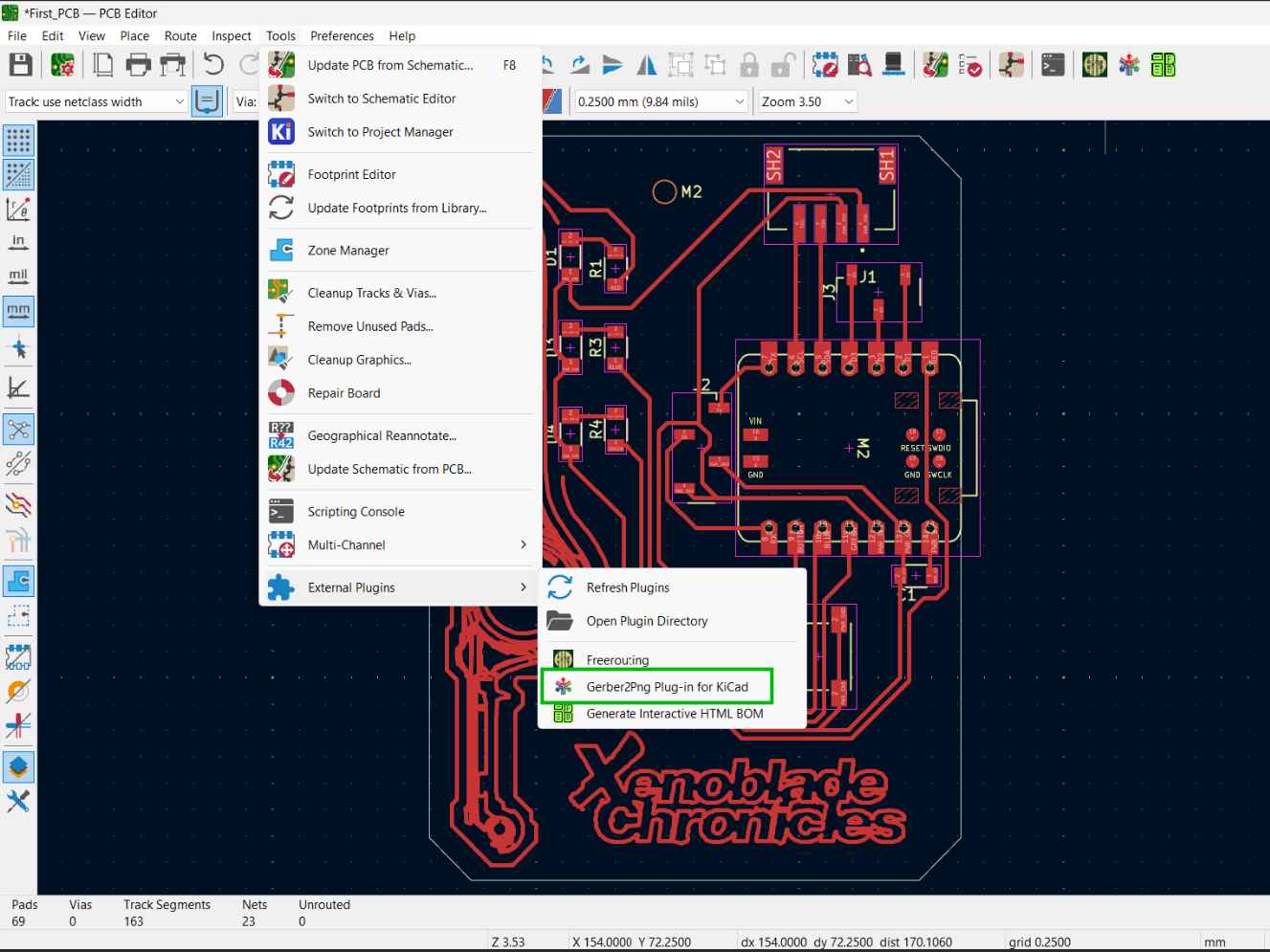
Now we can find this extension in external plug-ins.
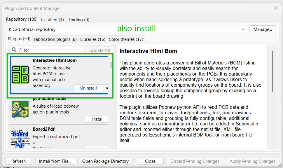
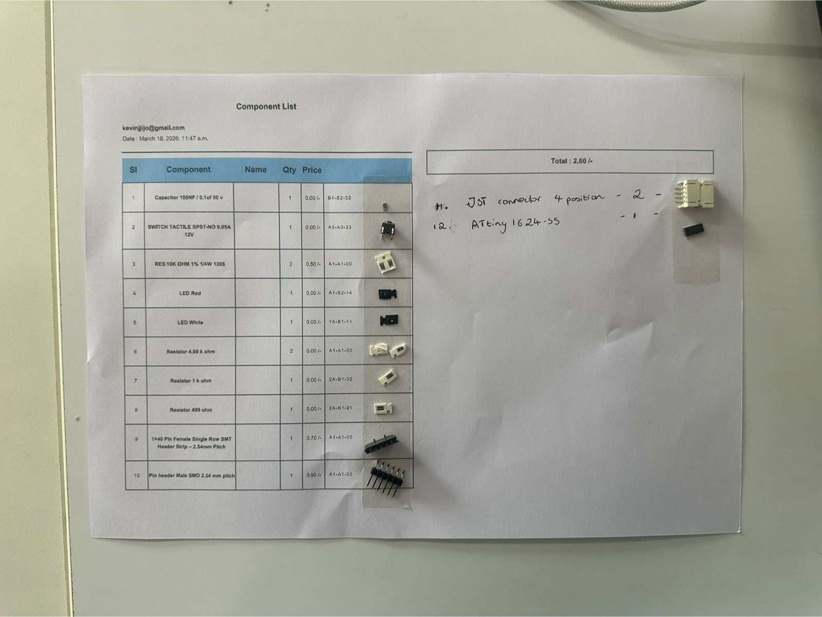
Also download the HTML BOM generator. We use this Bill of Materials to keep track of the components.
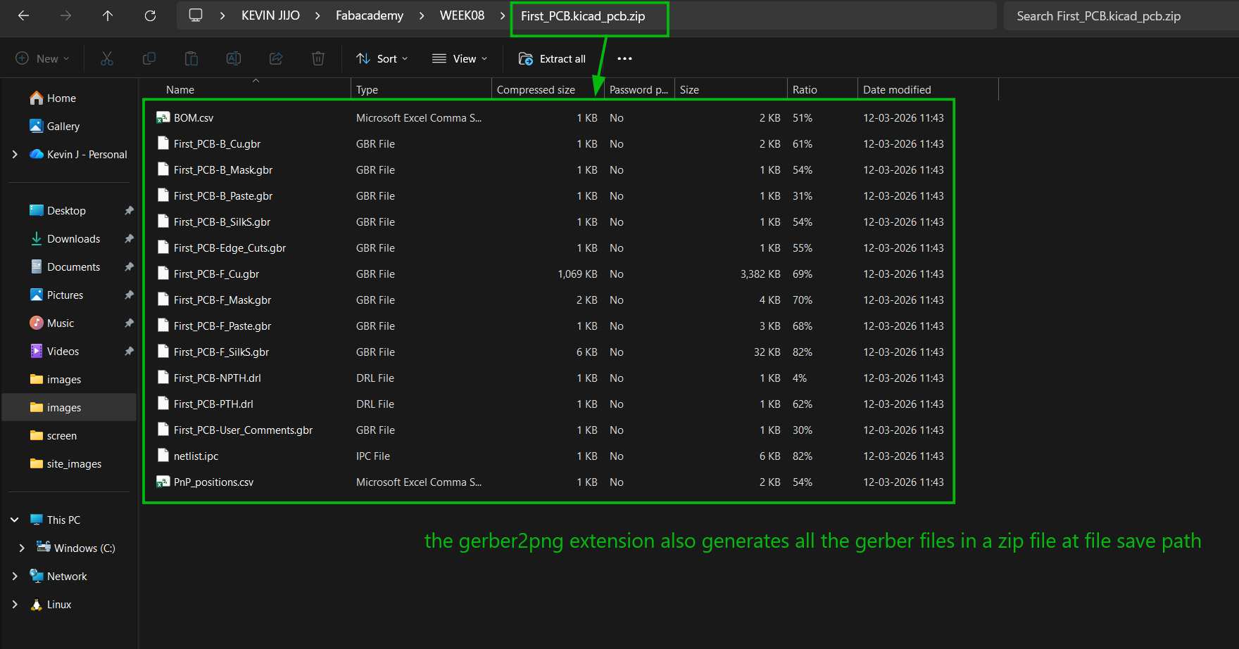
When we generate the PCB, it opens Gerber2PNG in your browser and also generates all the necessary Gerber files in the project file location.
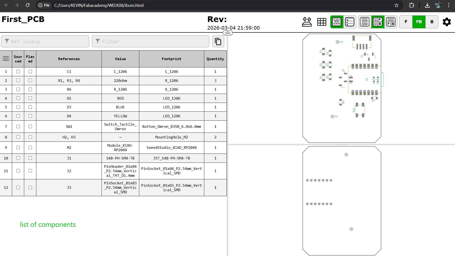
BOM (Bill of Materials): list of components presently being used in KiCad.
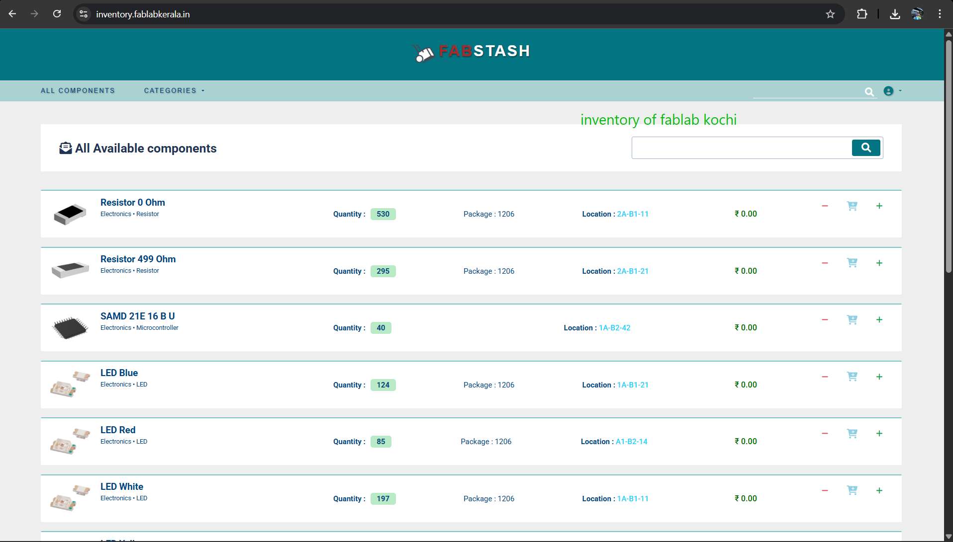
List of components presently available in the inventory.
A 1206 resistor is a Surface Mount Device (SMD) resistor, commonly used in electronics for its manageable size in hand-soldering and good power dissipation.
MODS online: modsproject.org
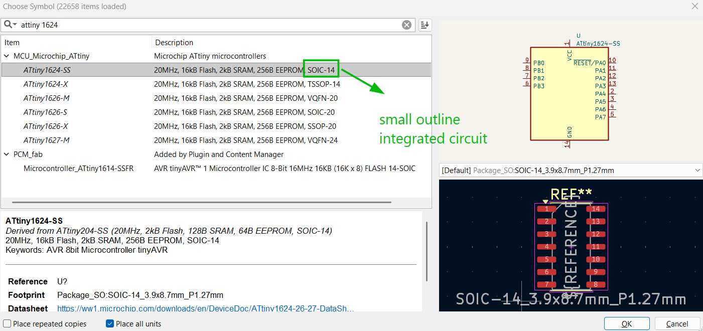
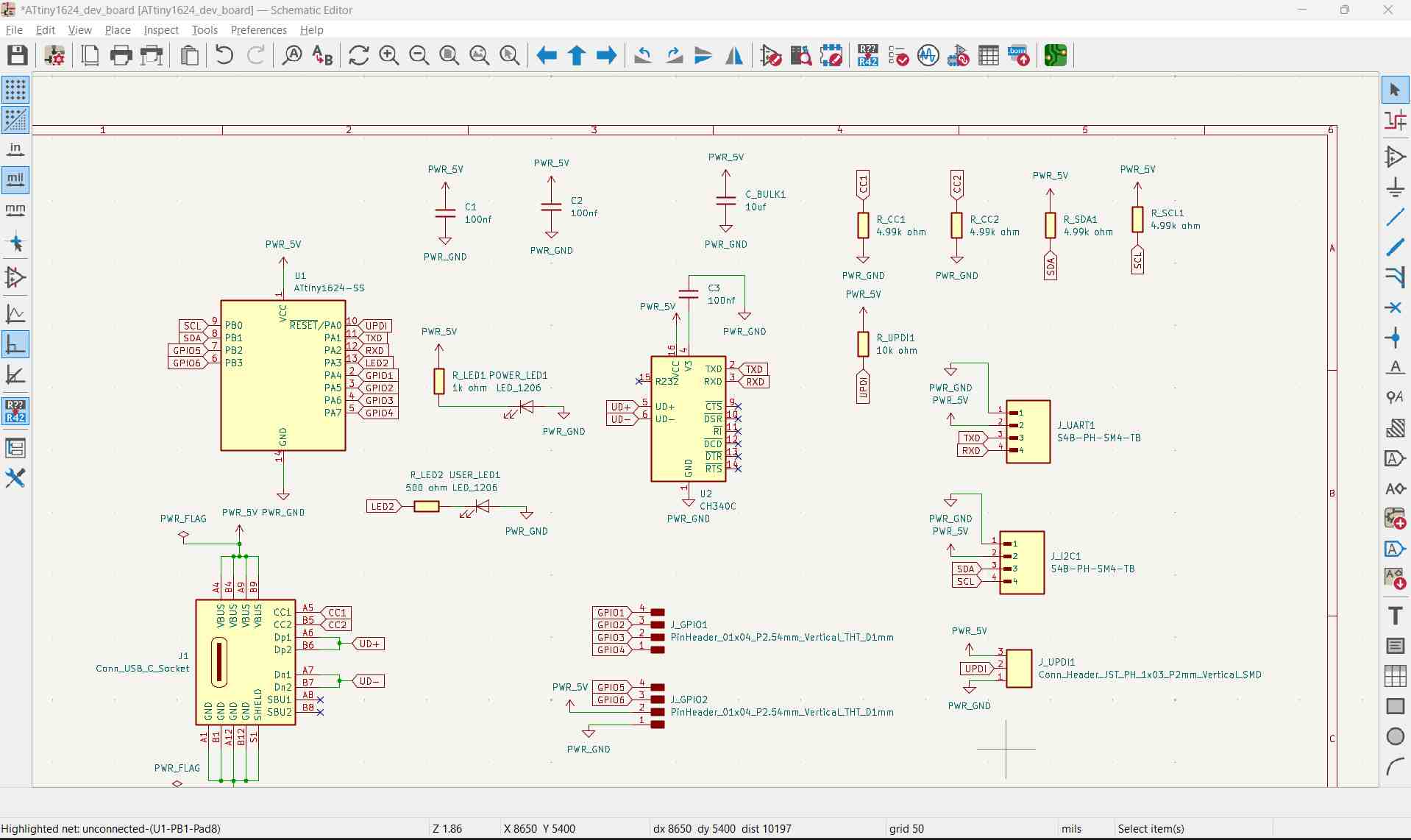
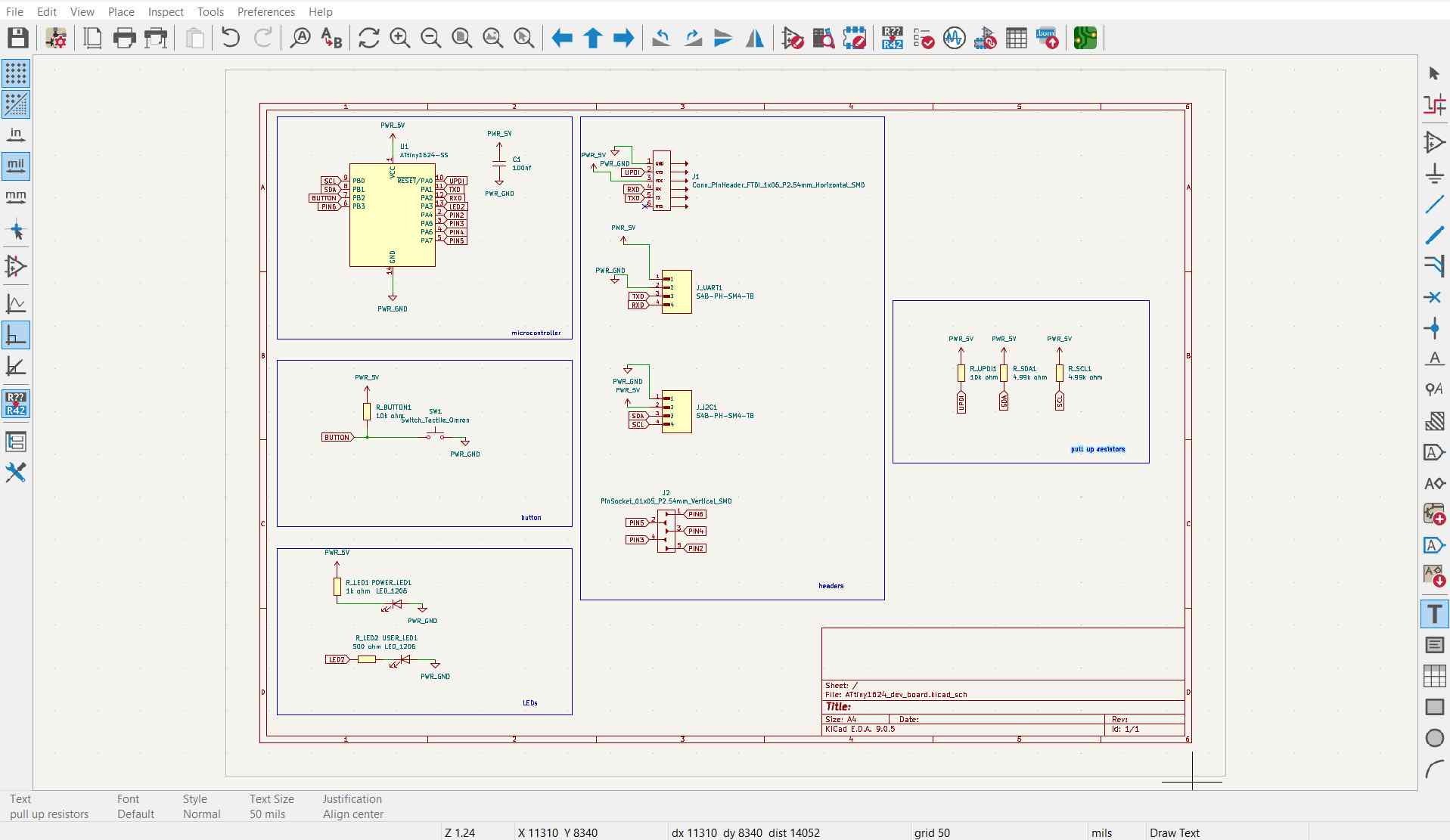
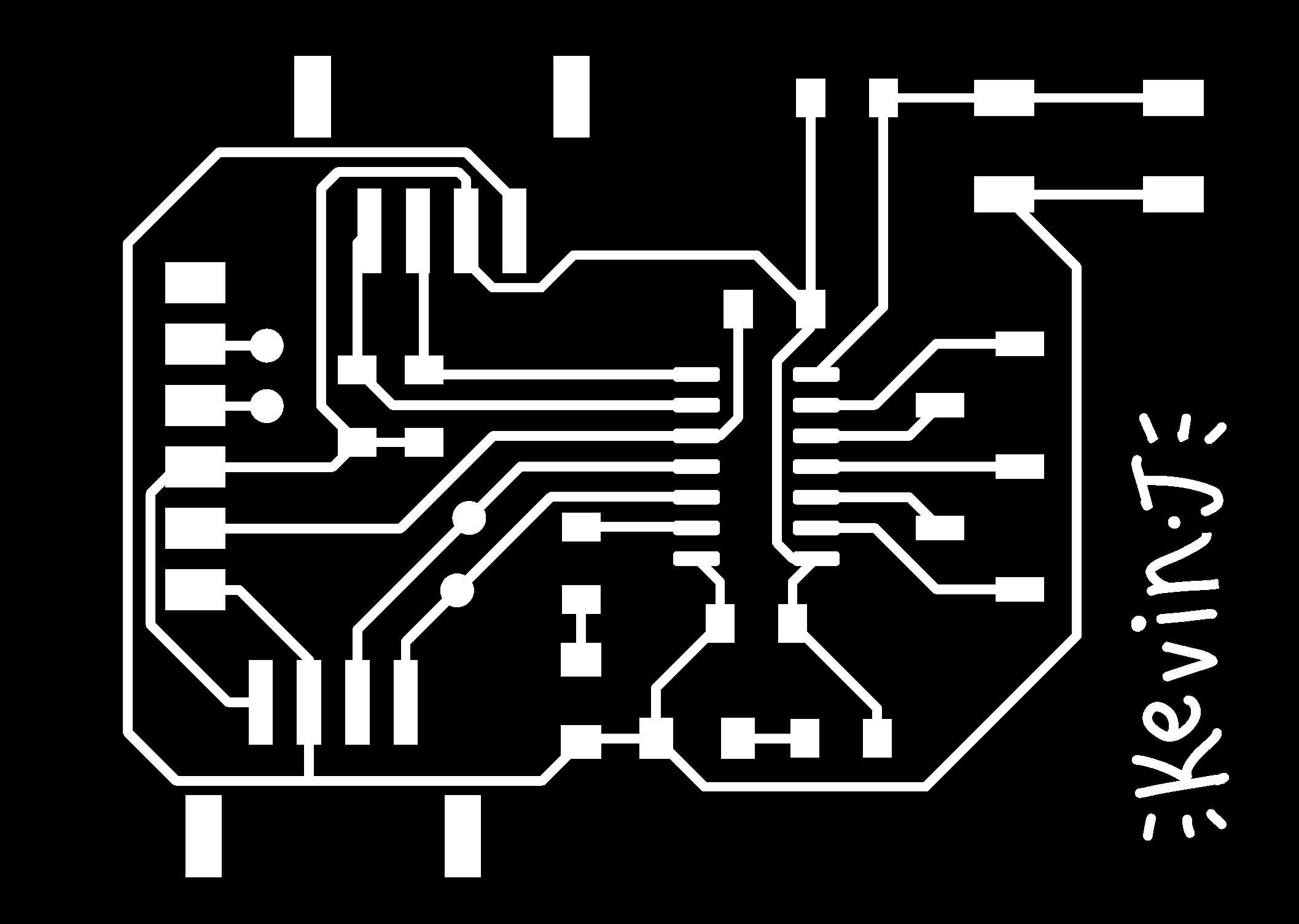
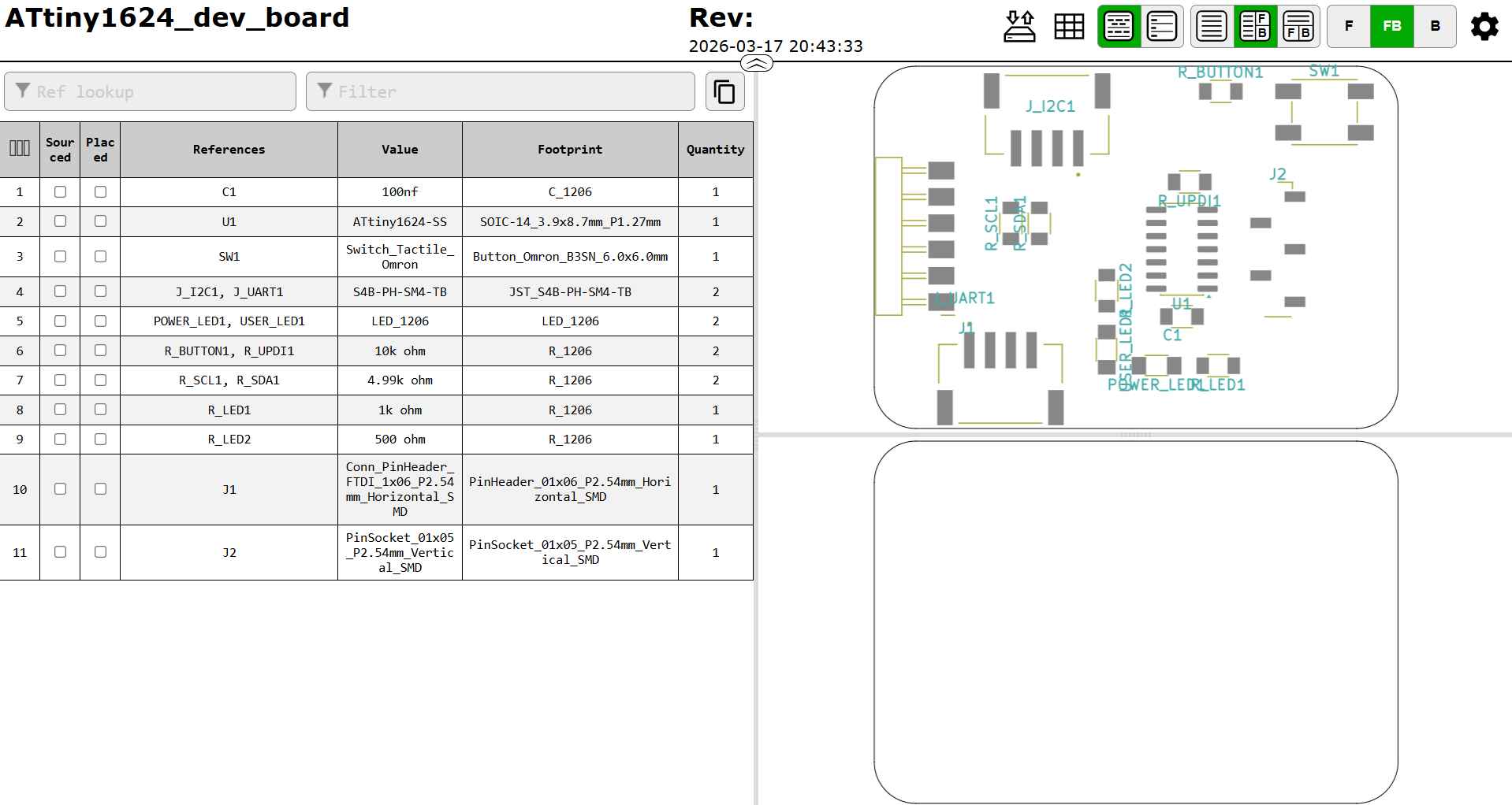
Designing the ATtiny1624 development board.
https://ww1.microchip.com/downloads/aemDocuments/documents/MCU08/ProductDocuments/DataSheets/ATtiny1624-26-27-DataSheet-DS40002234B.pdf
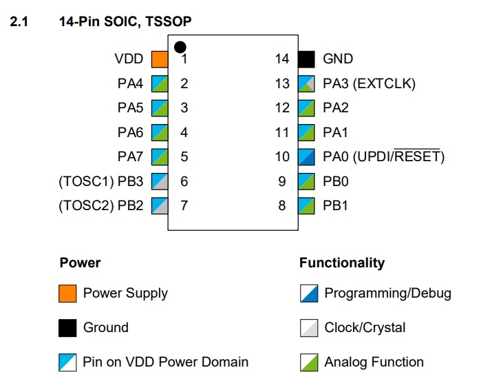
SOIC is easier to manually solder. The 1624 has 14 pins.
For constructing the development board, I will be focusing mainly on various communication protocols like I2C and UART, and also UPDI for programming.
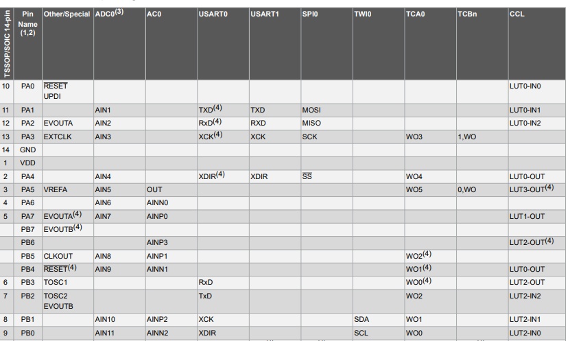
So the connections that will be available will be: PA0 for UPDI, PA1 TX and PA2 RX for UART, PB1 SDA, PB2 SCL for I2C, PA3 GPIO or ADC, PA4–PA7 GPIO, PB pins also GPIO, a reset pin, a power indicator LED, and a user LED for blink test.
USB-C through-hole connector.
CH340C USB to Serial Converter: ATtiny1624 has no native USB peripheral, so you need a USB-to-UART bridge chip for virtual COM port serial debugging.
I2C pull-ups: place 4.7kΩ resistors near the header, tied to 3.3V (no internal weak pull-up).
Crystal not needed (ATtiny1624 has a 16/20 MHz calibrated internal oscillator).
USB power only: 5V from USB → LDO → 3.3V (100 mA LDO).
UPDI: 3 pins (GND, UPDI, VCC)
I2C: 4 pins (GND, VCC, SDA, SCL)
UART: 4 pins (GND, VCC, TX, RX)
GPIO: 4-pin strips along the edge
CH340C at 5V: Fully supported. VCC = 5V, V3 pin gets 100 nF capacitor to GND.
ATtiny1624 at 5V: Fully supported. Runs up to 20 MHz at 5V. I2C pull-ups go to 5V instead of 3.3V.
JST SH, PH, and XH connectors are their pitch (pin-to-pin spacing), size, and power ratings. SH is the smallest, PH is mid-sized, and XH is the largest.
First I thought I’d go about making the dev board like this so it could be powered on its own, but I thought it could be programmed via serial like an Arduino. It can only be done using UPDI, so I scrapped this plan and just made a header.
DTR (Data Terminal Ready) is a hardware control signal in RS-232 serial communication.
This wasn’t the right approach for this week. A simple FTDI programmer makes more sense for this IC.
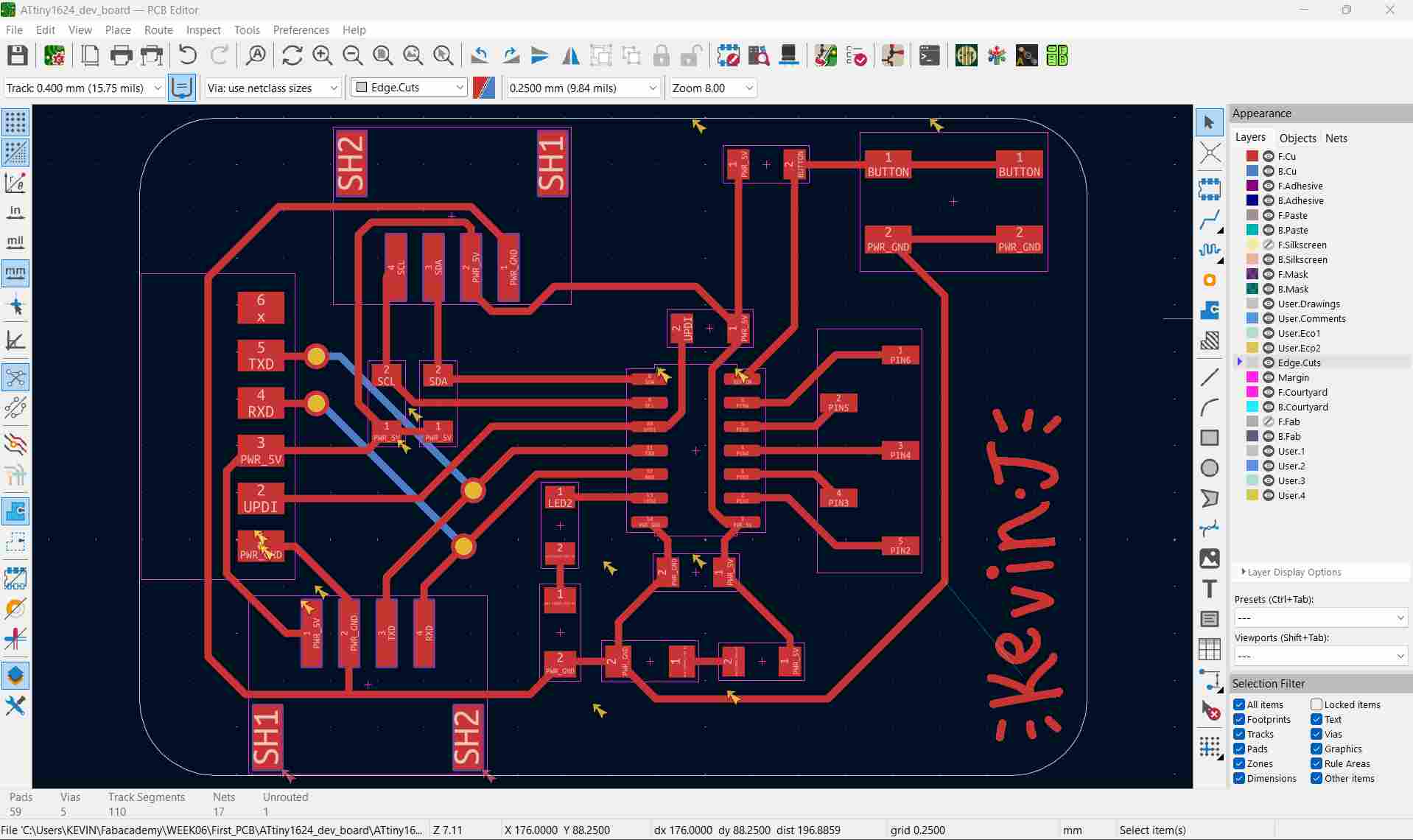
Differential pair maintains the same length as seen in USB D+ and D−.
I wanted to have very short RX and TX lines, and I also wanted to try two-sided PCB milling and learn the process around that, so I chose to route RX and TX through vias.
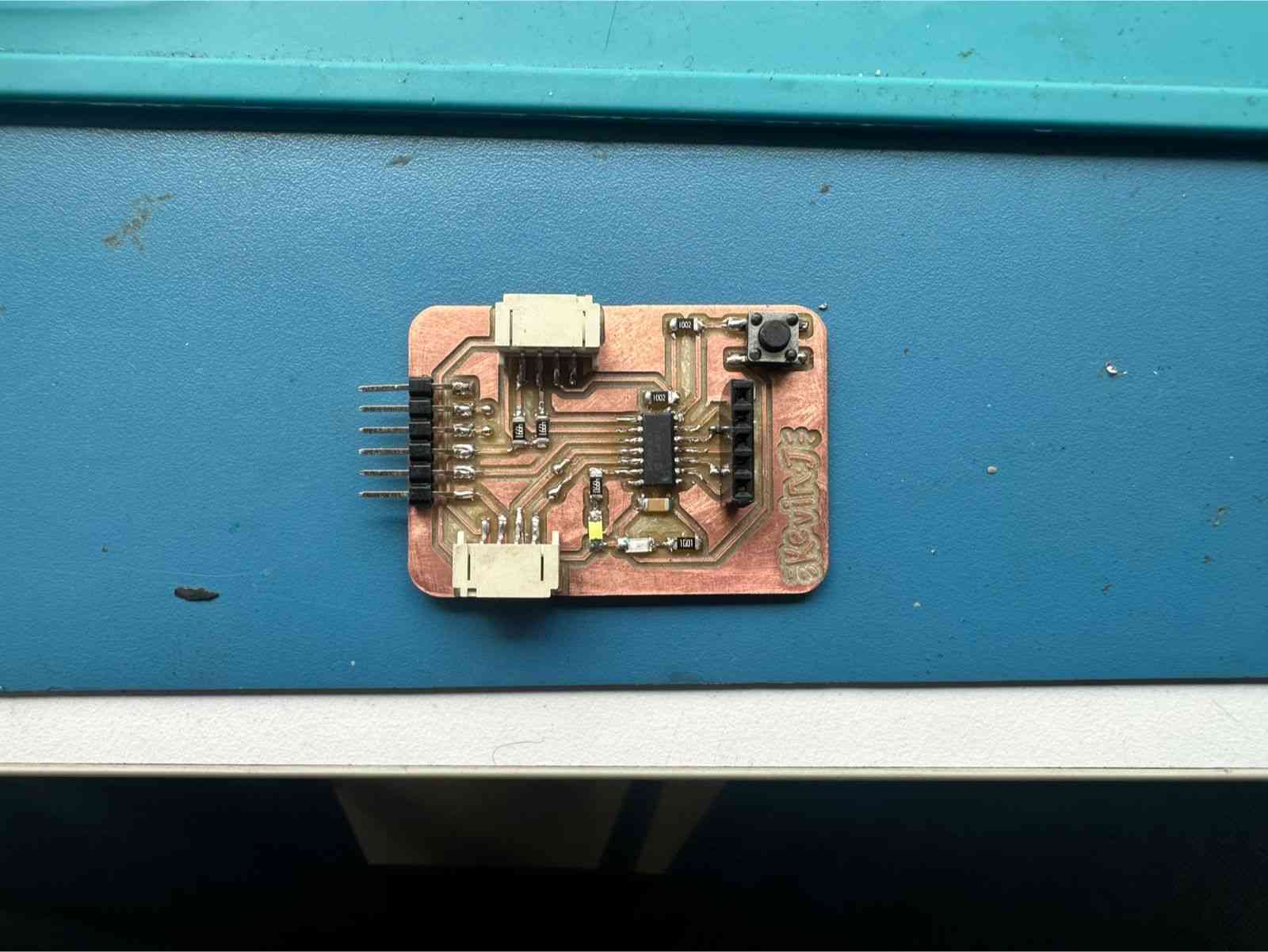
It’s an ATtiny1624 dev board with I2C, UART connectors, GPIO connectors, programmable using UPDI, with a user LED, power LED, and a programmable button.
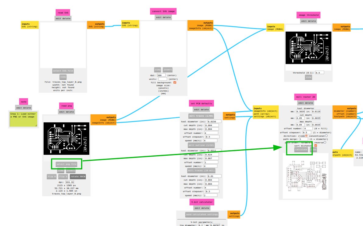
Now using the Gerber2PNG plugin we can easily get the PNGs.
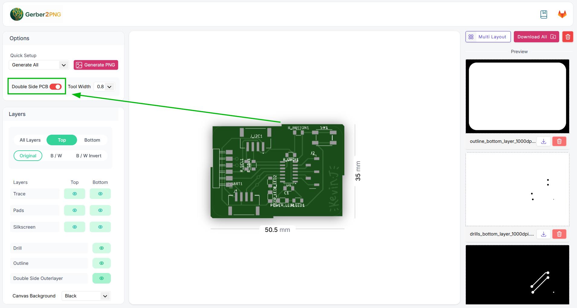
From here you can download a ZIP file containing all the PNG traces, including traces, drills, and outline for both sides. In this case there are 6 since it is a double-sided PCB.
Traces top layer
Drills top layer

Outline top layer

Traces bottom layer

Drills bottom layer

Outline bottom layer

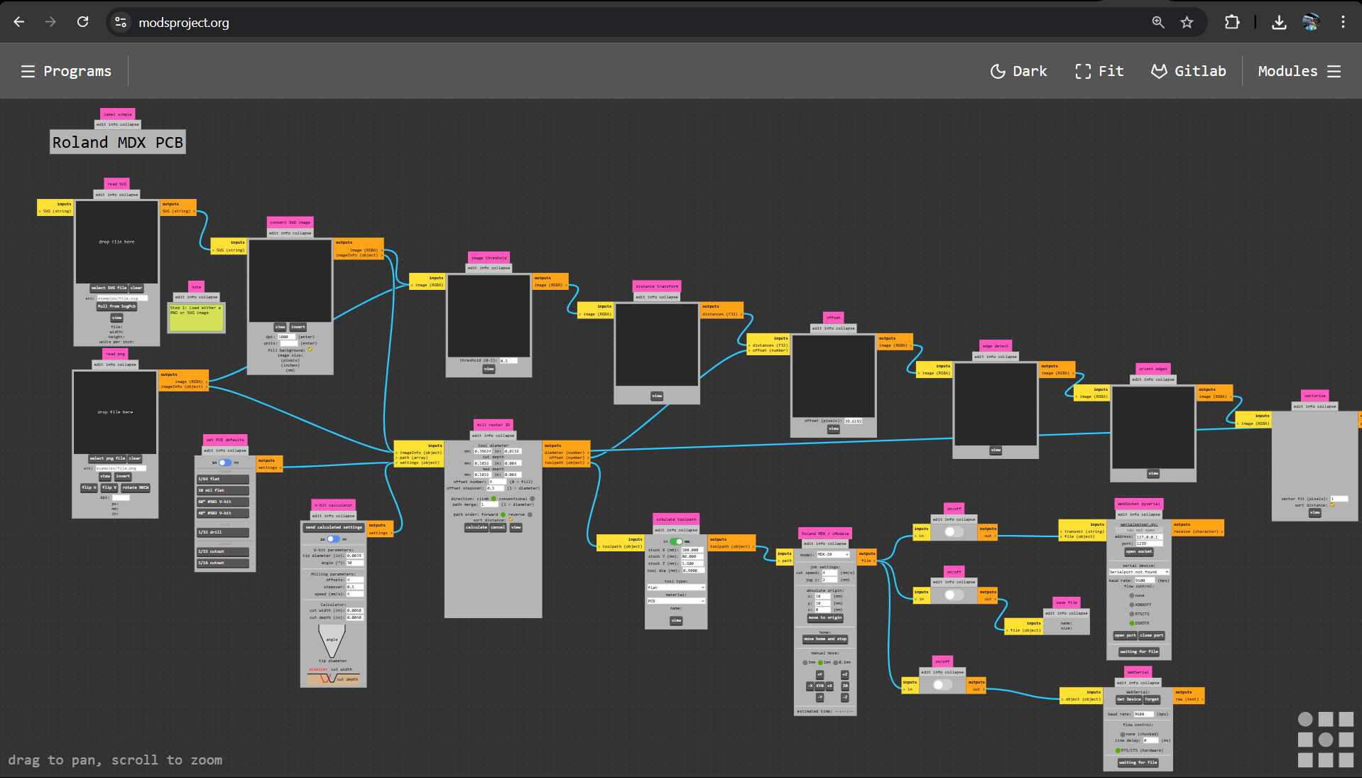
Using the Gerber2PNG plugin, the entire process is made very streamlined. We can move forward to milling on the Roland MDX PCB mill very quickly. We will be using MODS.
PCB milling and MODS
We can use the MODS interface to communicate with the Roland PCB mill.
To load the plate onto the machine, apply double-sided adhesive to one side and place it within the device bed.
Cut the necessary adhesive size out.
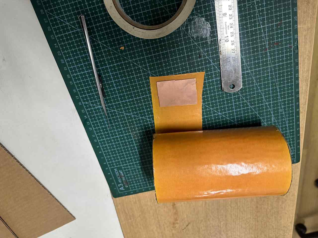
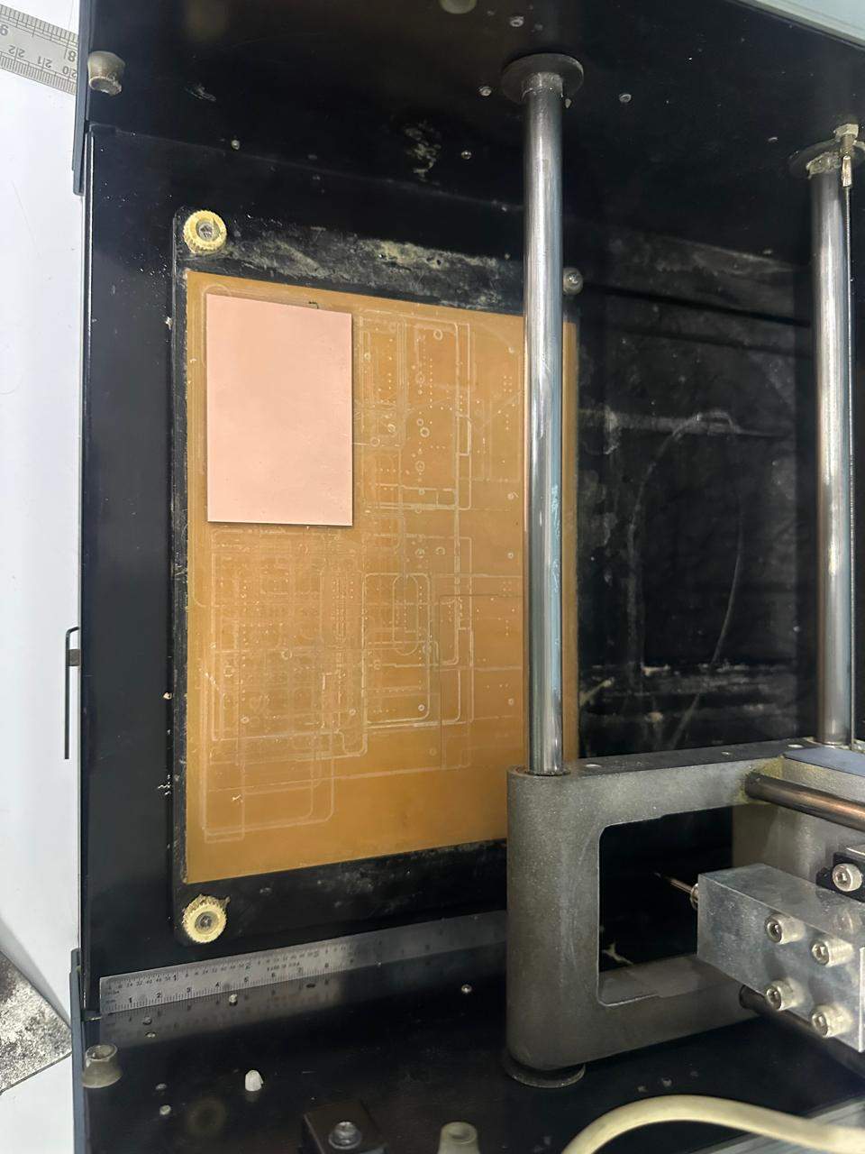
Place the plate somewhere within the bed. Try to align it with the X and Y axes of the machine.
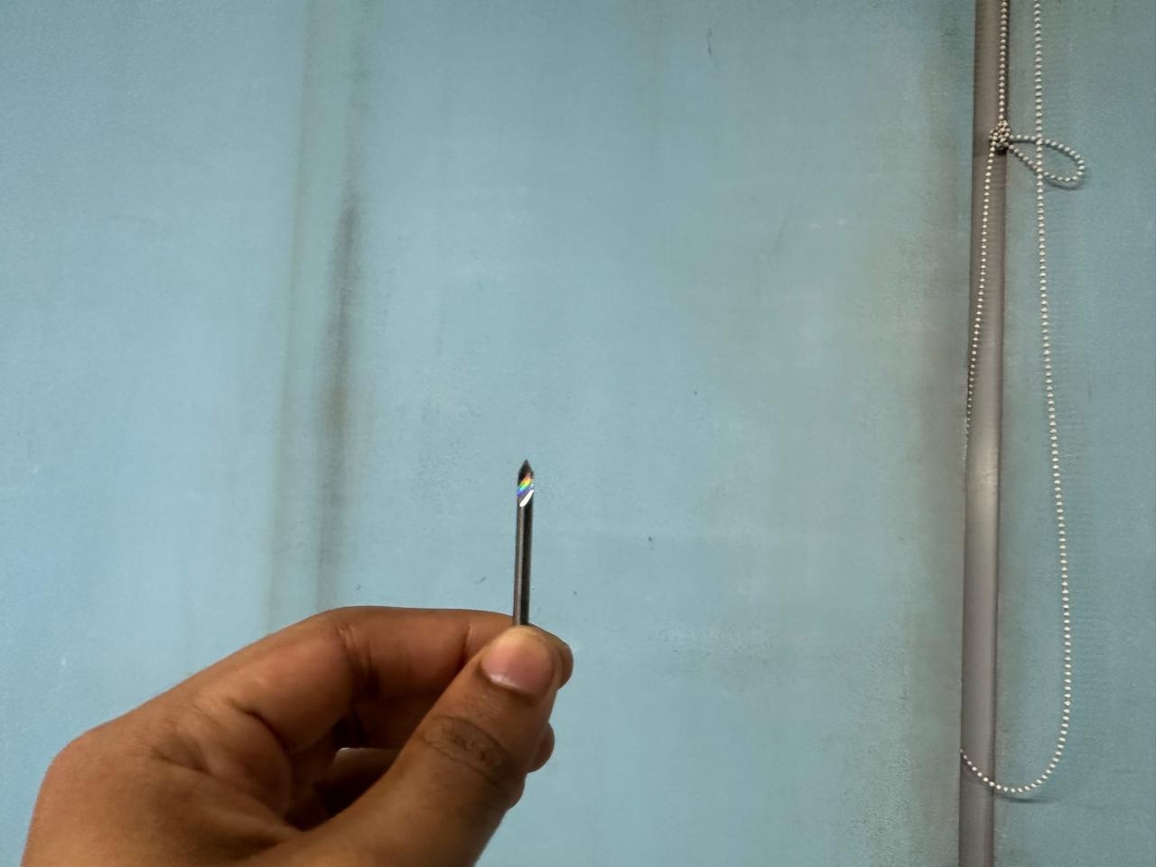
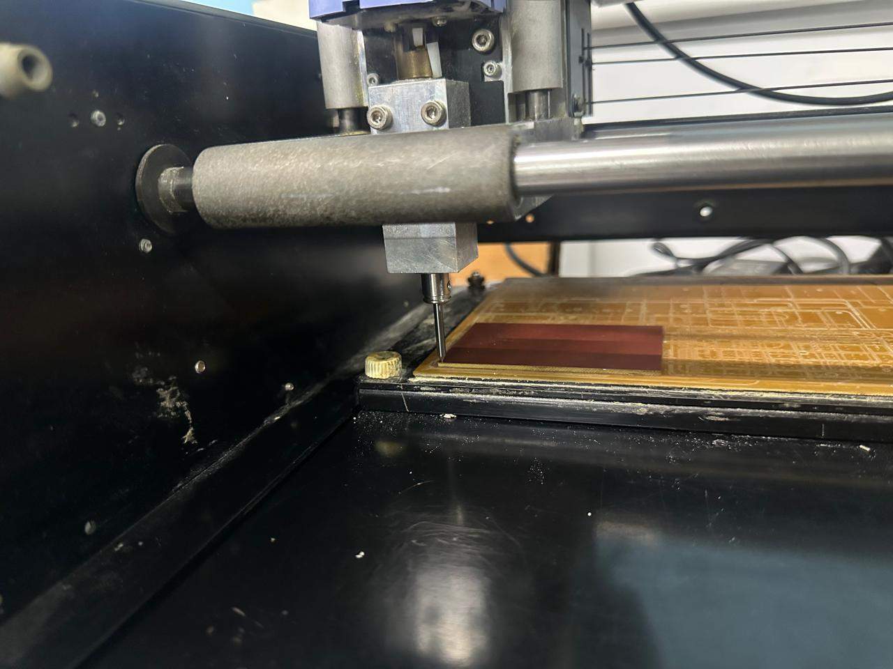
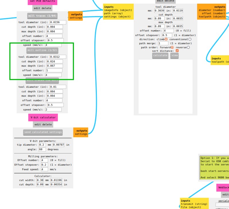
Let’s set up the bit now.
We are going to use two tools: the V-bit 0.2 mm tip end mill and the 1/32 (0.8 mm) end mill for drilling and outline.
The 1/32 (0.8 mm) tool end
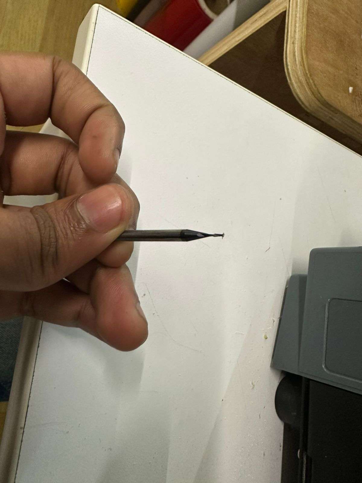
The V-bit tool end
To change bits, move the spindle to a safe position using MODS.
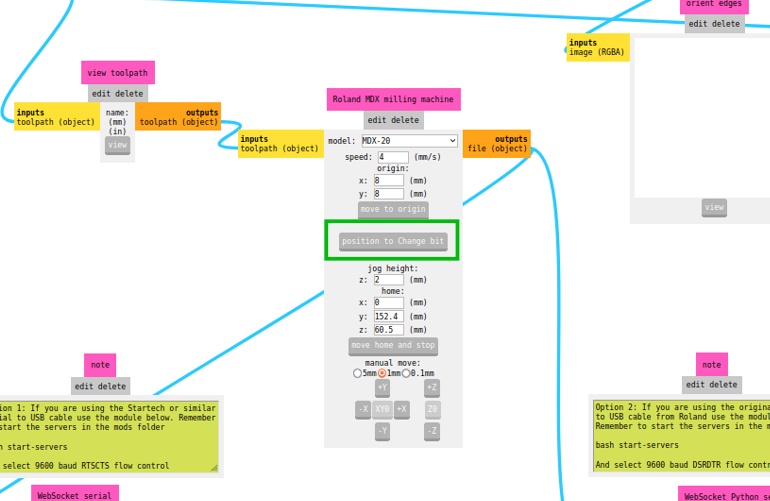
Use an Allen key to loosen the bit and insert the desired tool.
We will etch the traces first. Work from inside to outside: traces → drills → outline.
Now set X, Y, Z zeroes.
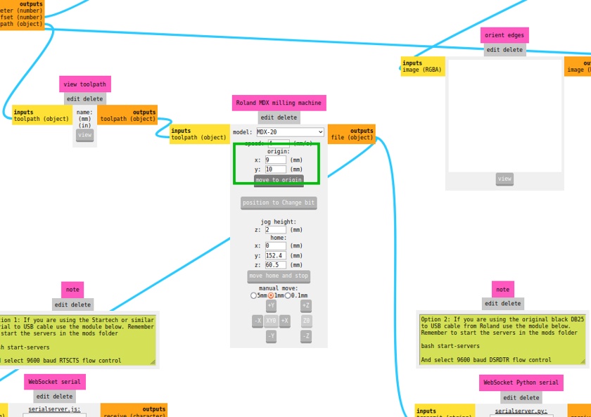
Z zero is set manually by lowering the bit until it touches the surface, then tightening it.
Set tool parameters using the V-bit calculator. Depth = 0.09, offset = 4.
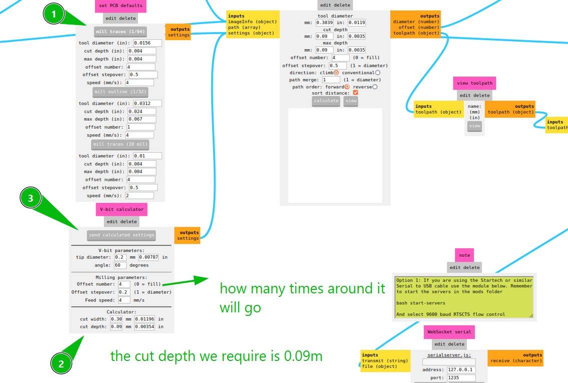
Select the correct PNG and calculate the toolpath.
Open socket and send file.
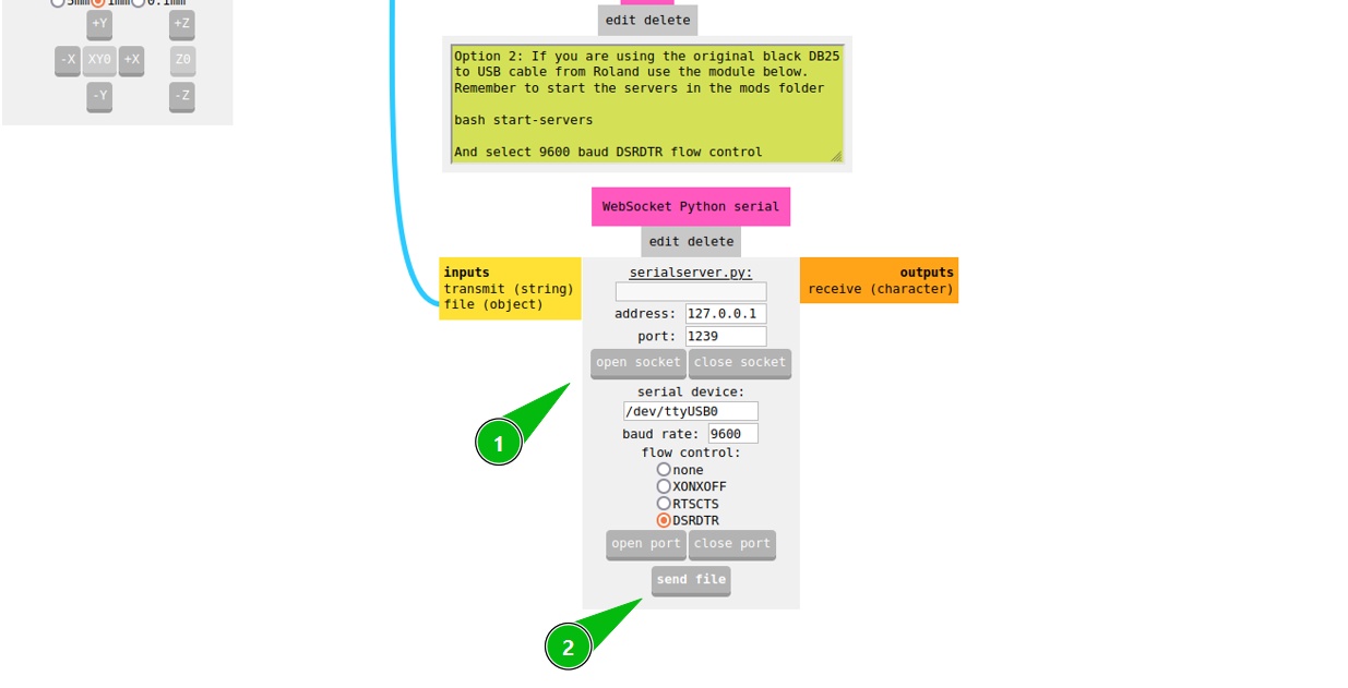
If there is an error, pause using the machine, close socket, and reset.
While milling, check depth and clearance.
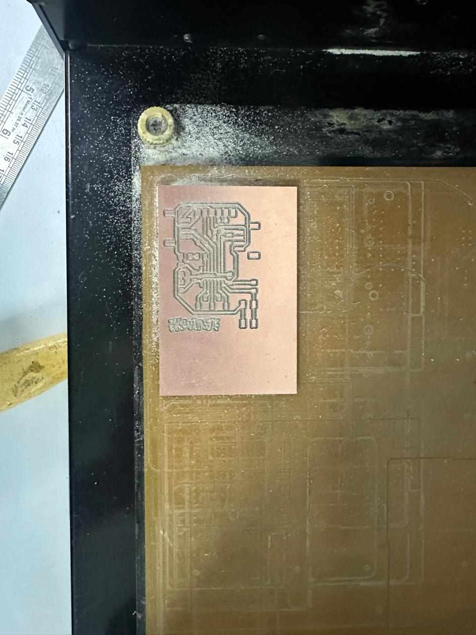
The top traces are complete.
Now drill and outline using the 0.8 mm bit.
Send the drill file.
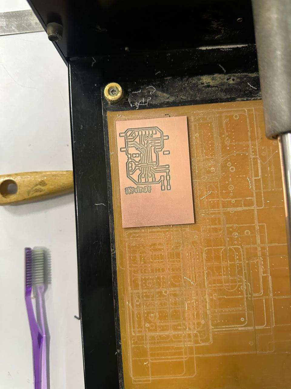
It might not drill fully; it will be completed from the other side.
Now cut the outline.
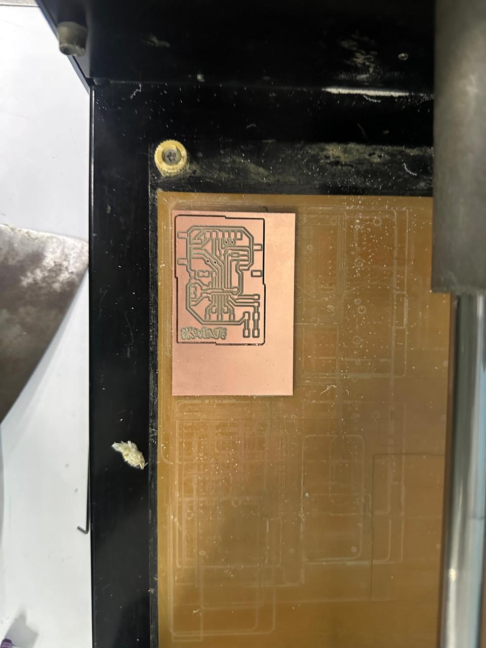
Peel it out, clean adhesive, flip, align, and repeat for bottom layer.
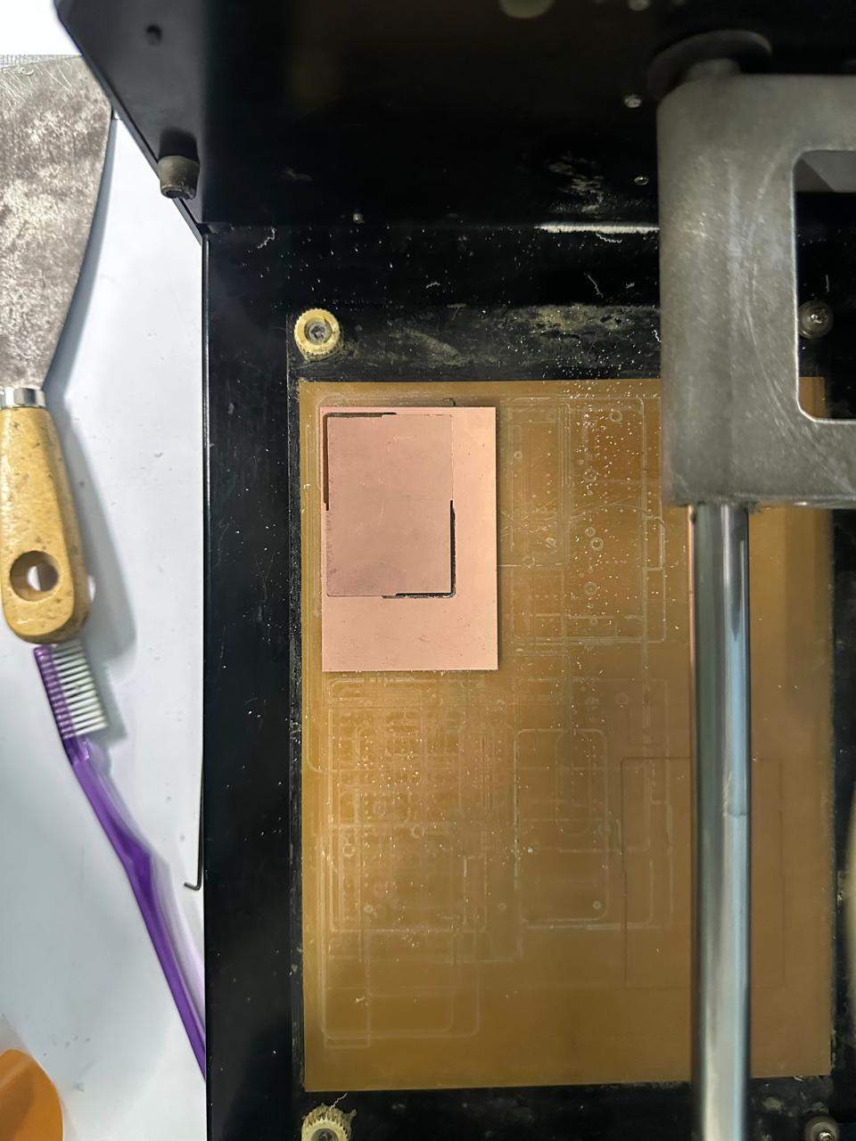
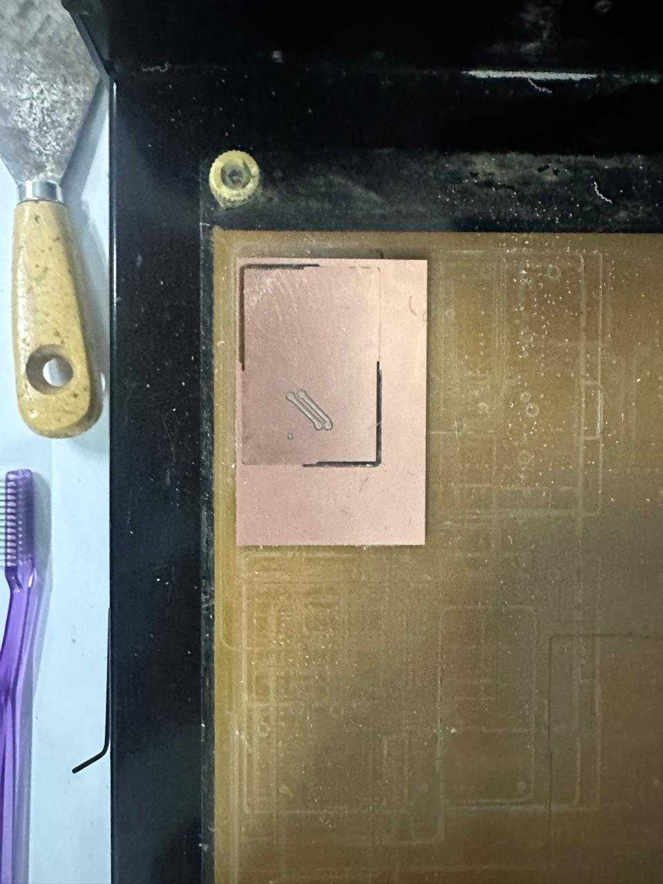
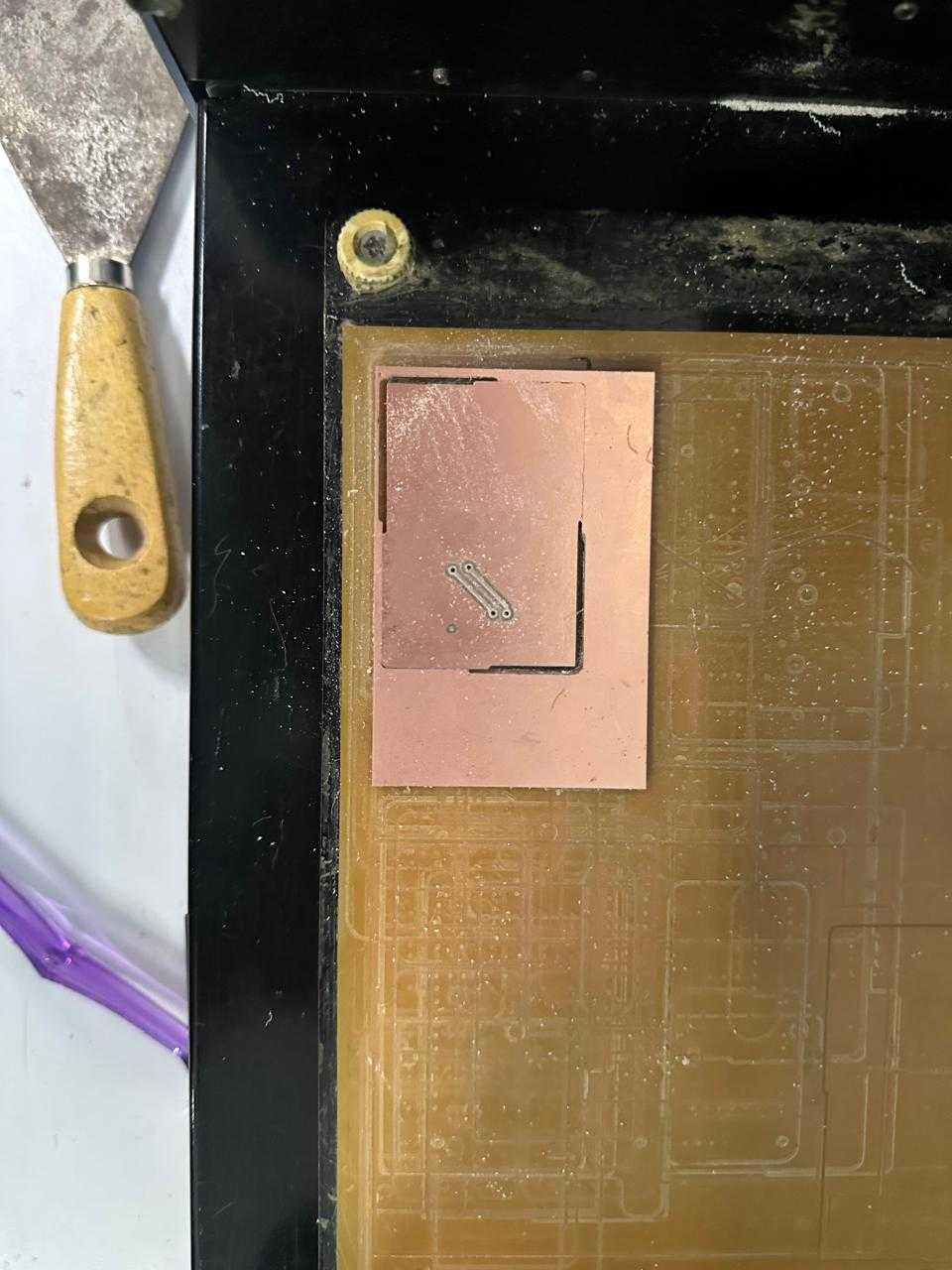
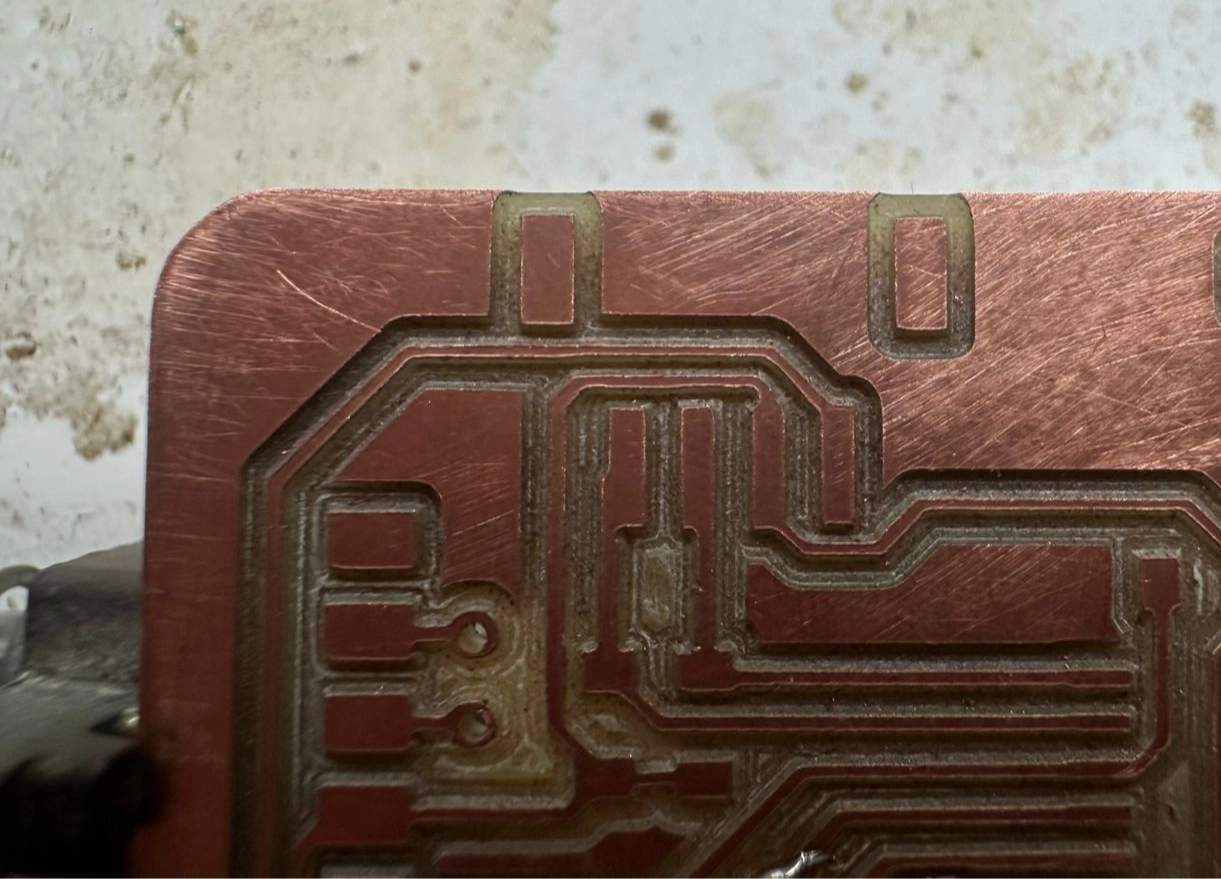
Clean the board and remove debris.
Soldering
Use HTML BOM to track components.
Inventory link used to request components.
Soldering workstation.
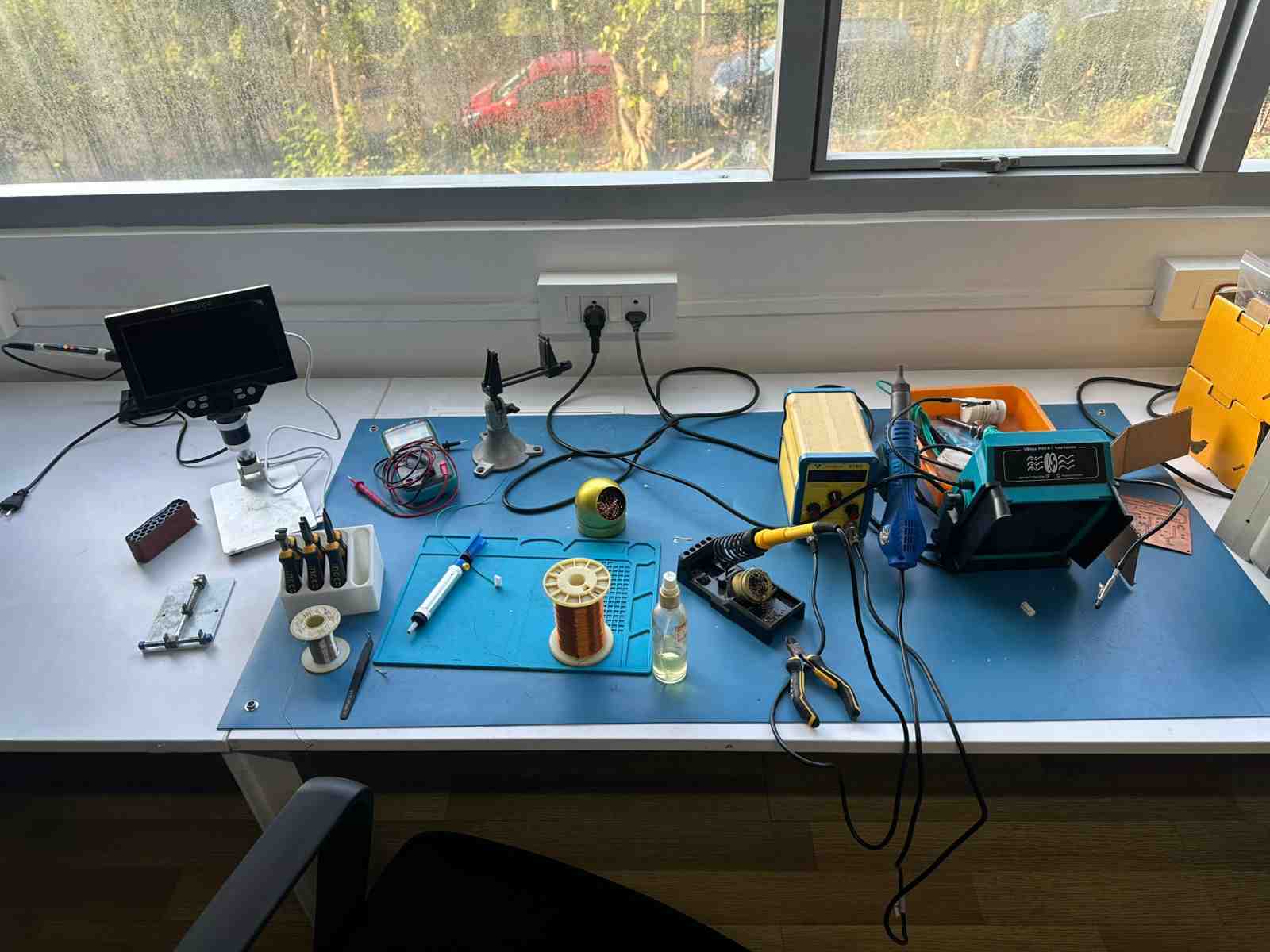
Keep ventilation on and wear a mask.
Sand PCB before soldering.
Clamp the board.

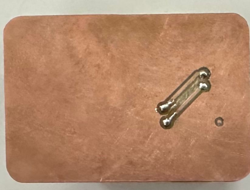
Solder by heating pad and applying solder.
Start with vias, then small components.
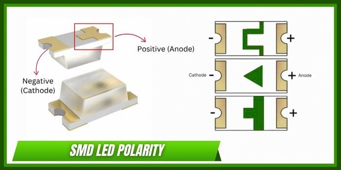
Check diode orientation.
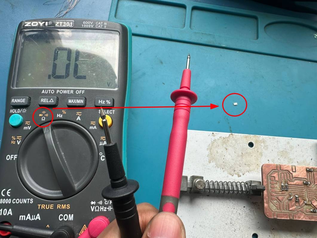
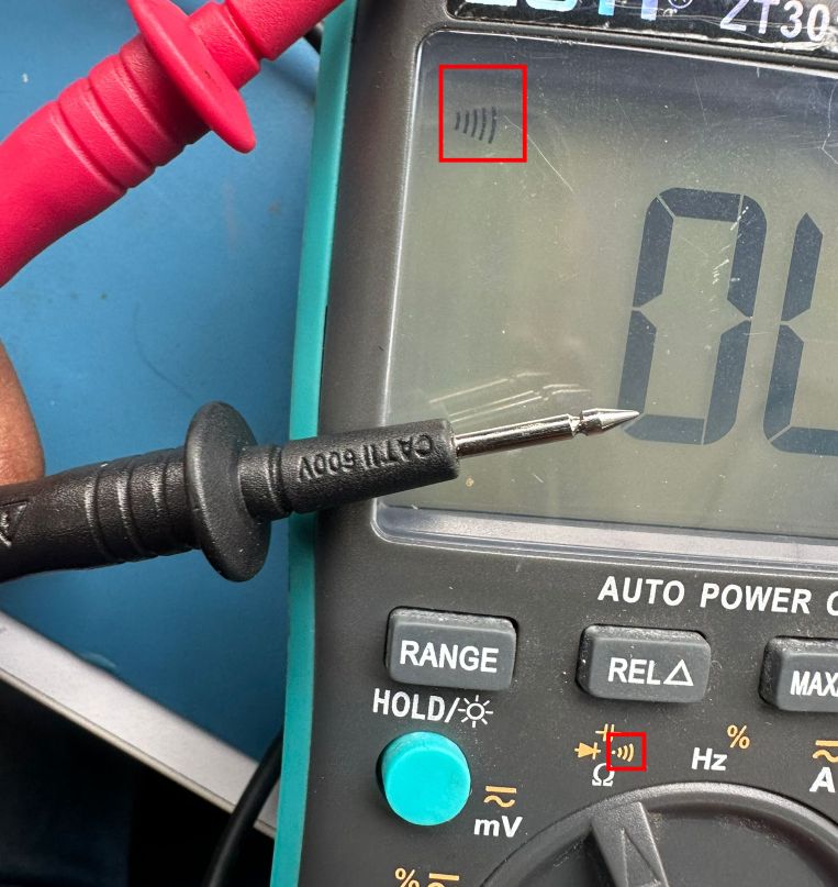
Check continuity with multimeter.
Testing the Board
UPDI Programming
UPDI is a single-wire programming interface used in modern AVR microcontrollers.
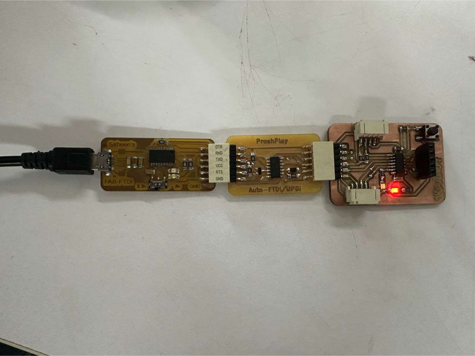
Used a UPDI programmer designed by Saheen Palayi, who has documented it really well.
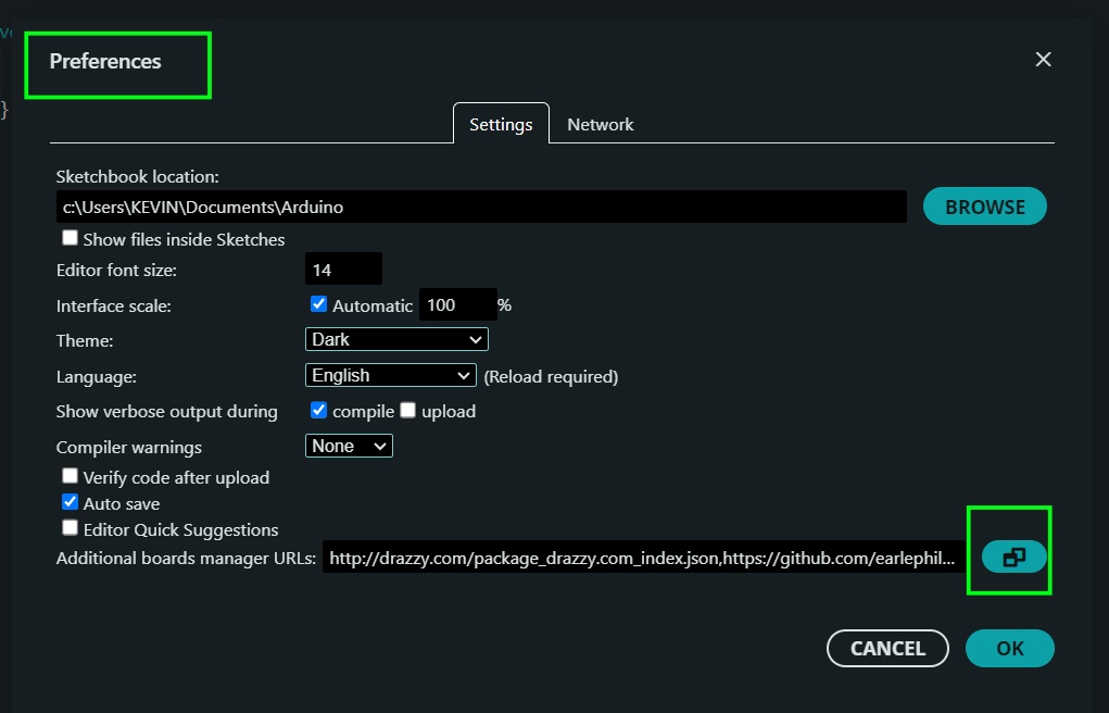
To set up the ATtiny board in Arduino IDE, add this link to the Additional Boards Manager URLs.
http://drazzy.com/package_drazzy.com_index.json
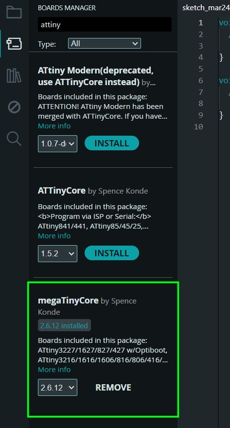
Now, in Boards Manager, install MegaTinyCore to your local libraries.
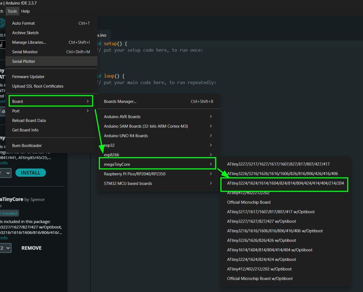
You can now choose the correct board. I used the ATtiny1624.
To find the correct port, you can usually use the Port option in Arduino IDE, or check Device Manager to identify it.

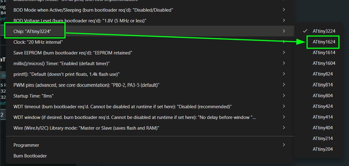
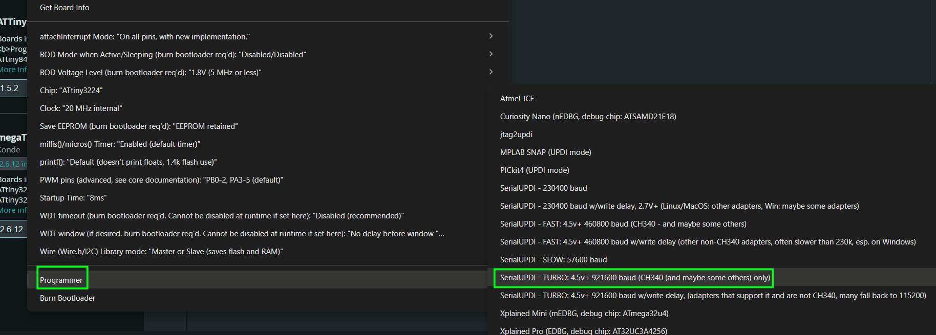
Now choose the correct chip configuration.
Then select the UPDI programmer. Everything should work; I chose the fastest option (Turbo).
You can now program the ATtiny microcontroller.
I connected RX and TX to PA1 and PA2, which correspond to TXD1 and RXD1. Since this is not the default serial interface, I used Serial.swap(1); in the setup function to switch to the alternate serial.
#define LED_PIN PIN_PA3
#define BUTTON_PIN PIN_PB2

void setup() {
  pinMode(LED_PIN, OUTPUT);
  pinMode(BUTTON_PIN, INPUT_PULLUP);
}

void loop() {
  if (digitalRead(BUTTON_PIN) == LOW) {
    digitalWrite(LED_PIN, HIGH);
  } else {
    digitalWrite(LED_PIN, LOW);
  }
}
This is to check if the board can be programmed and to verify button and LED.
The UART serial connector is not working as of yet.