Group Assignment
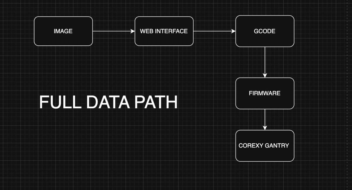
Pixel-Art is an open-source CNC machine that automatically places beads into a grid of holes on an acrylic sheet, producing physical pixel art from digital images. The machine uses a CoreXY motion system for fast, precise XY movement and a bead dropper mechanism as the end effector.Below is the slide of our presentation made in Canva: .
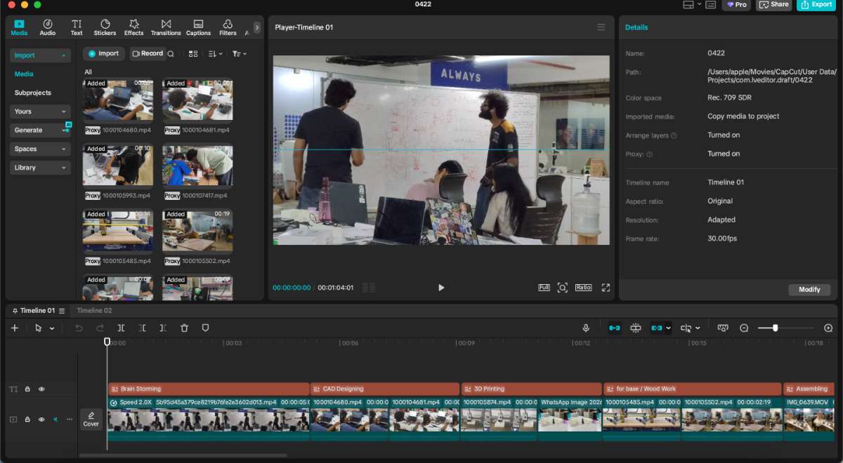
The project video was edited in Capcut
 Final Output :
Click here to view our group assignment
Individual Contribution
For the machine week i was incharge of building the firmware , making the presentation slide & editing the video.
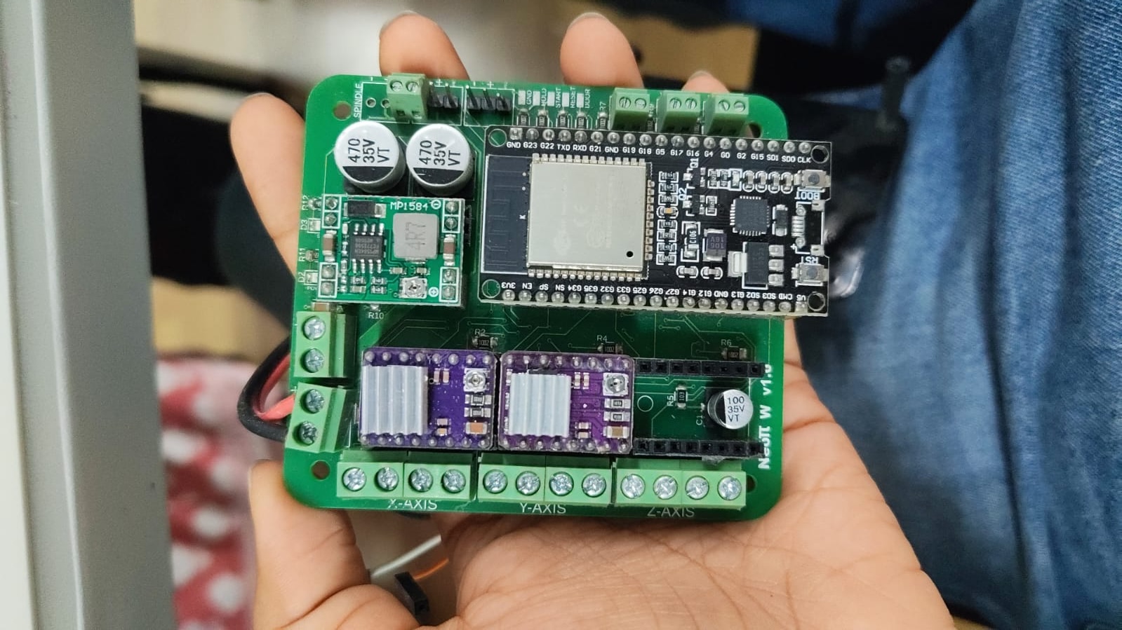
I used the updated version of the Neoπ Wireless CNC controller, originally developed by Saheen Palayi at Fab Lab Kerala. This board is a compact, all-in-one solution for ESP32-based motion control.
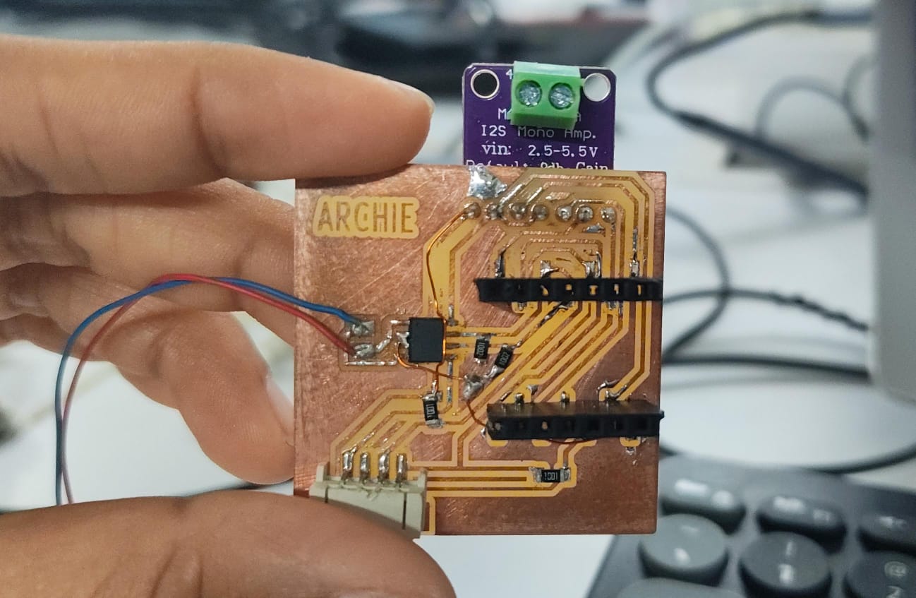
Vellichapad
 Oneof our Team member's Merin made an alternative board just in case we were not able to achieve the working of the project with this one.
Testing the Board on the Plotter Since are project was similar to one of the previous project - PolyPlot we were given a it to built the firmware till our model was ready.
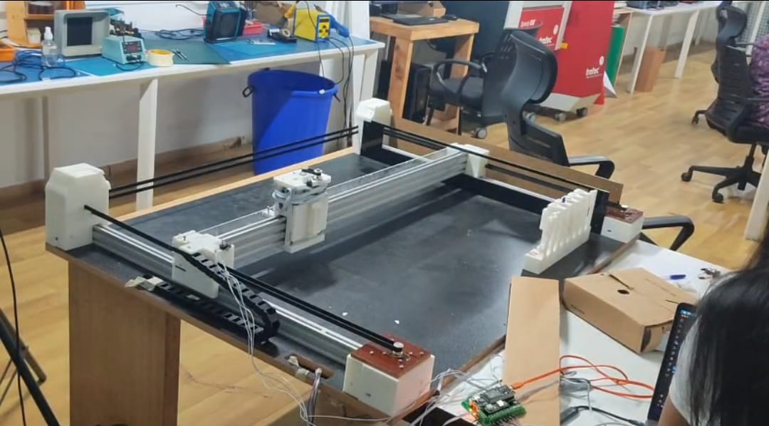 My first priority was to check if the vertical motion part of the old plotter would work using gcodes.
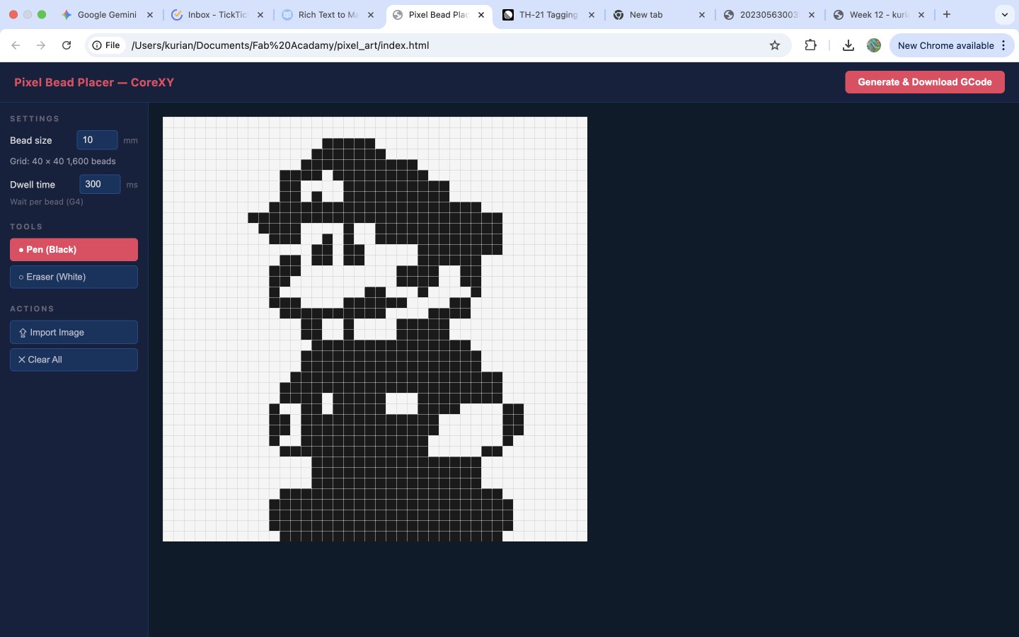
Now to set the baseline, My teammate Kurian built the Interface for PixelArt which turns a picture into a list of G-code instructions — go to this hole, drop a black bead, move to the next hole, drop a white bead — one line per pixel. On its own, that list is just text. The firmware is what reads each line, works out how far and how fast each motor has to turn, fires the correct bead feeder, and keeps everything coordinated so a bead lands in the right hole at the right moment.
Because our gantry uses a CoreXY belt arrangement, the two stepper motors don't map neatly to "X motor" and "Y motor." Every X or Y move is a combination of both motors turning together.
The firmware's most important job is to hide that complexity: the interface sends ordinary X/Y coordinates, and the firmware silently applies the CoreXY transform (steps_A = steps_X + steps_Y, steps_B = steps_X − steps_Y) to convert them into the correct motor steps. It also homes the machine to a known corner so that pixel (0,0) always means the same physical hole, and it switches the black/white bead feeders on and off on command.
Since the NeoPi already reads gcode i did not need to make a firmware from scratch , i needed to configure the firmware our fit the project, i used grbl_esp32 as the base firmware because it already handles the hard real-time work — step generation, acceleration planning, G-code parsing, homing, and Wi-Fi — out of the box. My job was not to write a motion controller from scratch, but to configure and adapt grbl_esp32 to our specific machine: our pin wiring, our CoreXY geometry, our steps-per-millimetre, our homing direction, and our two bead feeders mapped onto the outputs.
Requirements & How Each Was Addressed
R1 — Drive a CoreXY gantry
The two NEMA17 motors must move the carriage to any XY position on the 400×400 mm work area.
How addressed: grbl_esp32 has native CoreXY kinematics. Enabled by adding #define CUSTOM_CODE_FILENAME "../Custom/CoreXY.cpp" in the custom machine header (Pixelart.h). The firmware applies the CoreXY transform internally, so a single G0 X.. Y.. command resolves to the correct motor-A / motor-B steps automatically.

R2 — Accept standard G-code from the web interface
How addressed: grbl_esp32 is a GRBL 1.1-compatible parser. Kurian's interface exports GRBL-1.1 G-code (G21, G90, G28, G0, G4, M3/M4, M5, M30), which the firmware reads line-by-line with no translation layer.
R3 — Home to a known origin
Pixel (0,0) must always correspond to the same physical hole on the acrylic sheet.
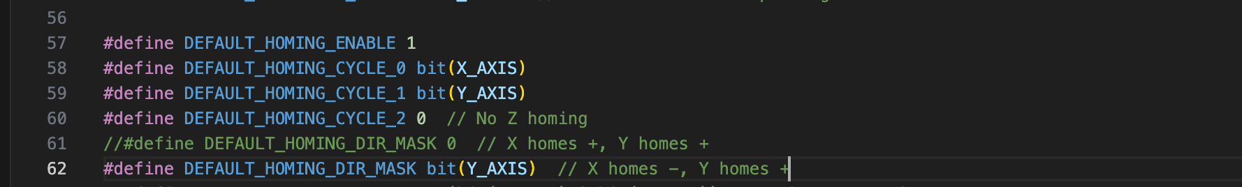
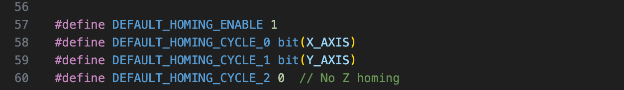 How addressed: Homing is configured against two limit switches (X and Y). $H / G28 drives the carriage into the switches, backs off, and sets machine zero — giving every G-code run a repeatable origin. Homing cycles, direction masks, and limit polarity are all configured in Pixelart.h.
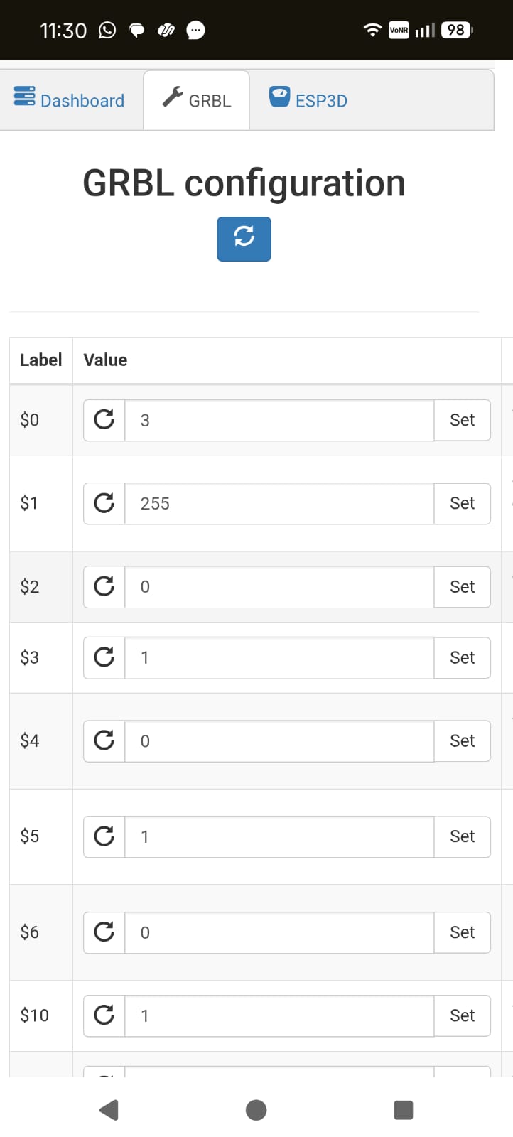
Some GRBL runtime settings:
How addressed: Homing is configured against two limit switches (X and Y). $H / G28 drives the carriage into the switches, backs off, and sets machine zero — giving every G-code run a repeatable origin. Homing cycles, direction masks, and limit polarity are all configured in Pixelart.h.
Some GRBL runtime settings: $22=1 ; homing cycle enable
$23=3 ; homing direction invert mask (seek negative X and Y)
$24=200 ; homing feed rate (mm/min)
$25=2000 ; homing seek rate (mm/min)
$27=2.0 ; homing pull-off distance (mm)
R4 — Convert real-world distance to motor steps correctly
A 6.5 mm bead pitch must move exactly one hole spacing.
How addressed: steps/mm is calculated from the belt-and-pulley geometry:
(200 steps × 32 microstep) / (20 teeth × 2 mm pitch)
= 160 steps/mm.
This calibration ensures commanded millimetres match physical travel.
R5 — Fire the correct bead feeder per pixel (black vs white)
How addressed: The two feeders are mapped onto grbl_esp32's spindle outputs: M3 (CW) = black feeder, M4 (CCW) = white feeder, M5 = both off. The interface only emits a new M3/M4 when the bead colour actually changes, keeping G-code compact. Example:
M3 S100 ; black feeder ON
G0 X5.00 Y5.00 F3000 ; move to hole
G4 P300 ; dwell — bead drops
G0 X15.00 Y5.00 F3000 ; next hole (still black, no M3 needed)
G4 P300
M4 S100 ; switch to white feeder
G0 X25.00 Y5.00 F3000
G4 P300
M5 ; all feeders off
R6 — Pause long enough for a bead to drop and seat
How addressed: The interface inserts a dwell (G4 P300) after each position.
G0 X5.00 Y5.00 F3000 ; rapid move to hole position
G4 P300 ; hold carriage still for 300 ms
grbl_esp32 honours the dwell, holding the carriage still for ~300 ms so the bead falls cleanly into the hole before the gantry moves on.
R7 — Communicate wirelessly during normal operation
How addressed: The ESP32's built-in Wi-Fi (used via grbl_esp32's networking layer, following the NeoPI_Wireless approach) lets G-code be streamed from the browser interface over Wi-Fi — no USB cable needed during a run.
Firmware Changes & Modifications During Development
The base firmware (grbl_esp32) was not edited at the C/C++ core level. Everything related to the project lives in one custom machine definition header (Pixelart.h).Build Configuration (platformio.ini)
; PlatformIO Project Configuration File
;
; Build options: build flags, source filter
; Upload options: custom upload port, speed and extra flags
; Library options: dependencies, extra library storages
; Advanced options: extra scripting
;
; Please visit documentation for the other options and examples
; https://docs.platformio.org/page/projectconf.html
[platformio]
src_dir = Grbl_Esp32
lib_dir = libraries
data_dir = Grbl_Esp32/data
default_envs = release
;extra_configs=debug.ini
[common_env_data]
lib_deps_builtin =
ArduinoOTA
BluetoothSerial
DNSServer
EEPROM
ESPmDNS
FS
Preferences
SD
SPI
SPIFFS
Update
WebServer
WiFi
WiFiClientSecure
[common]
build_flags =
-DMACHINE_FILENAME=test_drive.h
-DCORE_DEBUG_LEVEL=0
-Wno-unused-variable
-Wno-unused-function
[env]
;lib_deps =
; TMCStepper@>=0.7.0,<1.0.0
platform = espressif32@3.0.0 ; temporary fix for lost uart rx characters
board = esp32dev
framework = arduino
upload_speed = 921600
board_build.partitions = min_spiffs.csv
monitor_speed = 115200
monitor_flags =
--eol=CRLF
--echo
--filter=esp32_exception_decoder
board_build.f_cpu = 240000000L
board_build.f_flash = 80000000L
board_build.flash_mode = qio
build_flags = ${common.build_flags}
src_filter =
+<*.h> +<*.s> +<*.S> +<*.cpp> +<*.c> +<*.ino> +espressif32@3.0.0 is pinned on purpose — a newer platform version was dropping UART RX characters, corrupting streamed G-code. The comment stays in the file so nobody "upgrades" it back into the bug.
Development Journey — What Changed Along the Way I didn't land the firmware in one shot. Here's how i did it, including the wrong turns:
Phase 1 — Exploring a custom PicoNC firmware
I initially studied a PicoNC/Pico-based firmware sketch to understand the structure: stepper assignments, homing/state logic handling. With AI help(all AI conversaions will be listed at the end of the documentation), I explored rewriting it for CoreXY + bead placement — adding CoreXY coordinate conversion, simplifying from pick-and-place to push/drop, removing Z-axis logic, and adding a minimal G-code parser. This built my understanding of how motion firmware works, but the approach was abandoned once we decided to use the NeoPI board (ESP32-based) rather than a Pico.
Phase 2 — Pivoting to grbl_esp32
As mentioned in the beginning of the documentation we used the NeoPI CNC controller board from last year's Fab Academy. I attached the grbl_esp32 archive and the NeoPI machine header to the Codex session and asked how to integrate them. Codex inspected the GRBL architecture, the built-in CoreXY.cpp, and the NeoPI header's pin mappings, and recommended creating a custom machine header (Pixelart.h) based on NeoPI's pin layout with CoreXY enabled, so i replaced velichapad.h(which is the last years machine code) with Pixelart.h, i.e, removing/commenting out the non essentials and adding the Pixelart project essentials instead.
Pixelart.h:
#pragma once
// clang-format off
/*
NeoPI_W_v1.h
Part of Grbl_ESP32
Pin assignments for the NeoPI Wireless CNC Controller(3-axis), v1.0 and later.
https://github.com/saheenpalayi/NeoPI_Wireless
2018 - Bart Dring
2020 - Mitch Bradley
2022 - Saheen Palayi
2026 - Archita BK
Grbl_ESP32 is free software: you can redistribute it and/or modify
it under the terms of the GNU General Public License as published by
the Free Software Foundation, either version 3 of the License, or
(at your option) any later version.
Grbl is distributed in the hope that it will be useful,
but WITHOUT ANY WARRANTY; without even the implied warranty of
MERCHANTABILITY or FITNESS FOR A PARTICULAR PURPOSE. See the
GNU General Public License for more details.
You should have received a copy of the GNU General Public License
along with Grbl_ESP32. If not, see I had enabled CoreXY by adding #define CUSTOM_CODE_FILENAME "../Custom/CoreXY.cpp" to Pixelart.h. Then i tested the XY movement through the GRBL client config .
 Testing with G0 X10 through the terminal showed GRBL reporting position changes internally , but motors were not physically turning.the issue was traced to stale build artefacts, reflashing solved it.
Phase 4 — Homing and limit switches
Limit switch support was already present in the machine header. The key work was getting the homing direction mask and limit invert polarity correct so the carriage sought the right corner. So my understanding on GRBL's stepper driver only knows step pulses and direction pins and that "X+" and "home" are entirely defined by configuration masks was essential.
Phase 5 - Programming the Bead Allotter(Servo)
The Servo had a gear attached to it which was responsible for the movement of the slider plate,(check Kevin's documetation for a detailed description od the end effector) deciding which bead the end effector should let go, so finding out exactly how many degrees the servo should rotate for the bead to pass through the hole in the slider involved a lot of trial.
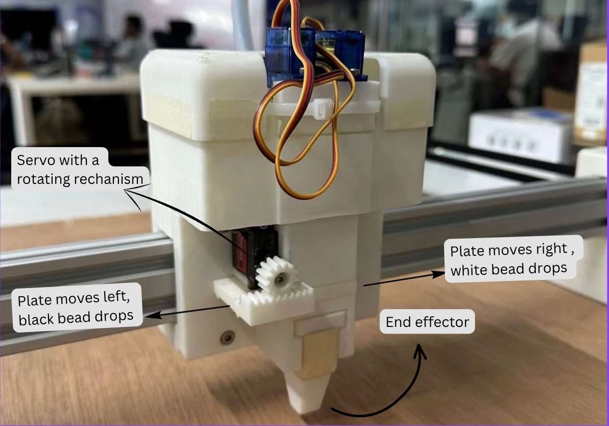
 Here, i had to manually type out machine codes in the terminal to see which one was accurate.
 After trials these values were confirmed as defaults :
M4 - Rotate counter-clockwise
M3 - Rotate clockwise
M3 S40 - Moves the slider to the left
M3 S79 - Slider is in rest position, beads are blocked
M3 S120 - Moves slider to right
Note : The color of the bead dropped completely depends on how the user allots the bead in the catridge, i.e if the left is filled with white beads instead of black you'll be getting an inversed output.
Final Output:
Firmware Logic — Block Diagram
 Decision flow inside the firmware:
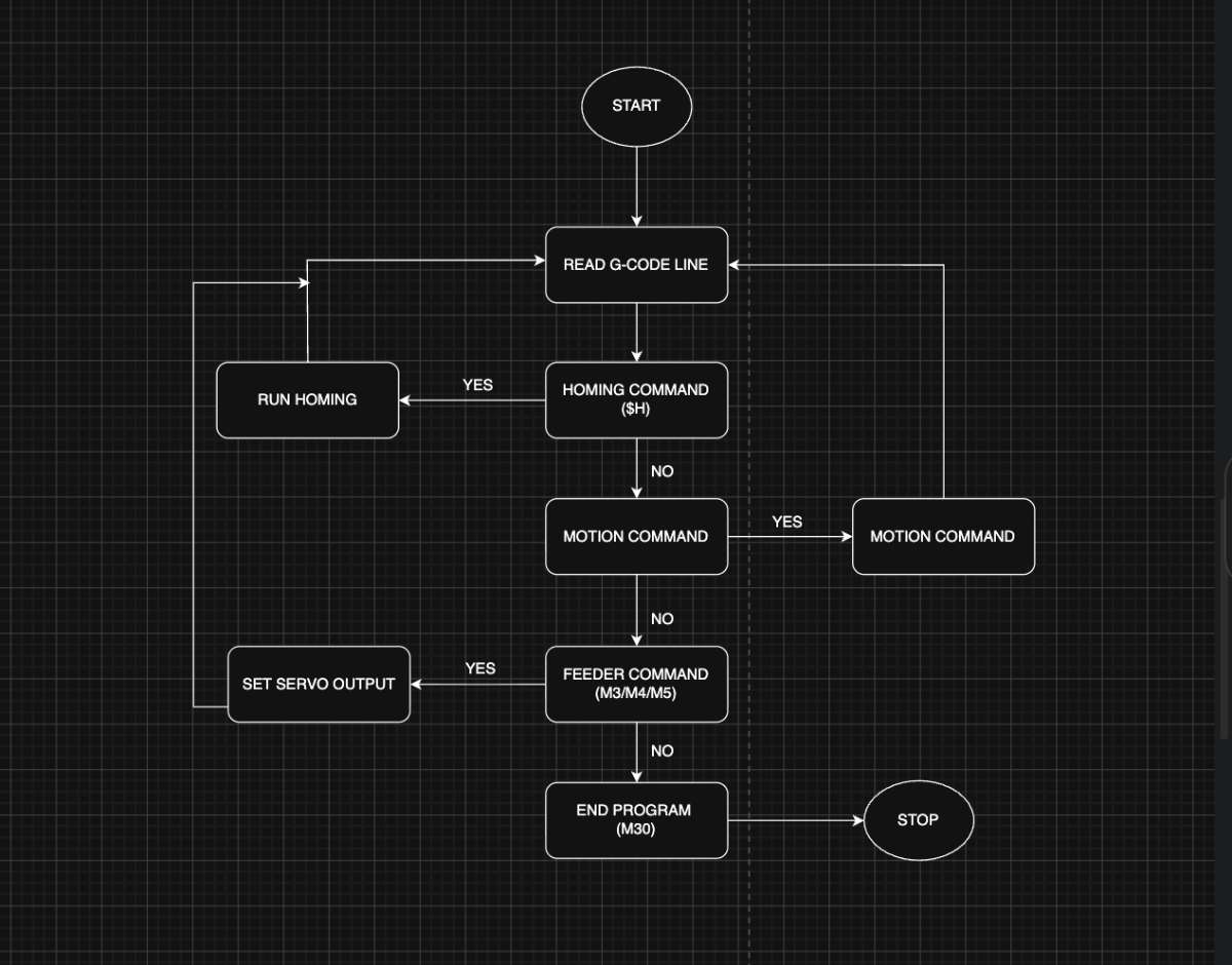
Conclusion
Final Files
AI PromptsFirmware Files