12. Mechanical Design, Machine Design
- Group assignment
- Design a machine that includes mechanism + actuation + automation + application
- Build the mechanical parts and operate it manually
- Document the group project
- Individual assignment
- Document your individual contribution
Group Assignment
Results can be found on the group assignment page of our lab.
Individual Assignment
Problem Definition
The objective of this project was to design a reliable end effector capable of dispensing individual black and white beads for a pixel art generating machine. The mechanism needed to accurately select between two bead colors, prevent jamming, integrate with the automated gantry system, and be simple enough to manufacture and assemble within the project timeline.
Exploring the Solution Space
Before starting fabrication, several concepts were explored for both the dispensing and actuation mechanisms. Different slider designs, dispensing methods, and motion conversion mechanisms were considered, including a scotch yoke and a rack-and-pinion system. Early prototypes were built to evaluate these ideas and identify issues such as poor tolerances, inconsistent bead flow, and hopper clogging. The observations from each prototype guided the next design iteration, resulting in a more reliable and manufacturable solution.
Development Timeline
- Concept Development: Brainstormed multiple dispensing mechanisms and selected the slider-based end effector concept.
- Prototype 1: Built a proof-of-concept to validate single-bead dispensing.
- Mechanical Redesign: Improved the slider, frame rigidity, and integrated a rack-and-pinion drive with a servo motor.
- Testing & Iteration: Identified hopper clogging and refined the design through multiple revisions.
- Final Assembly: Added the bead agitator, protective enclosure, and completed the fully functional end effector.
This week we were tasked with building a machine that incorporated a mechanism powered by an actuation system. The entire system also had to be automated with an application interface for user input. This was a fairly large task to complete individually, so the class was divided into two groups of five students, each group responsible for developing one machine.
After discussing several possible concepts, our group decided to build a pixel art generating machine that recreates images using black and white beads.
We divided responsibilities among the team members and I was assigned the design and development of the end effector. We discussed multiple approaches for bead dispensing and eventually arrived at the idea of a funnel bucket feeding beads continuously into a slider. The slider height would match exactly the height of a single bead so that only one bead could pass at a time. A single dispensing hole would release either a black or a white bead depending on the slider position. The slider always carries one black bead and one white bead, and the actuation selects which bead is dropped.
To validate the idea quickly, I built a rudimentary prototype.
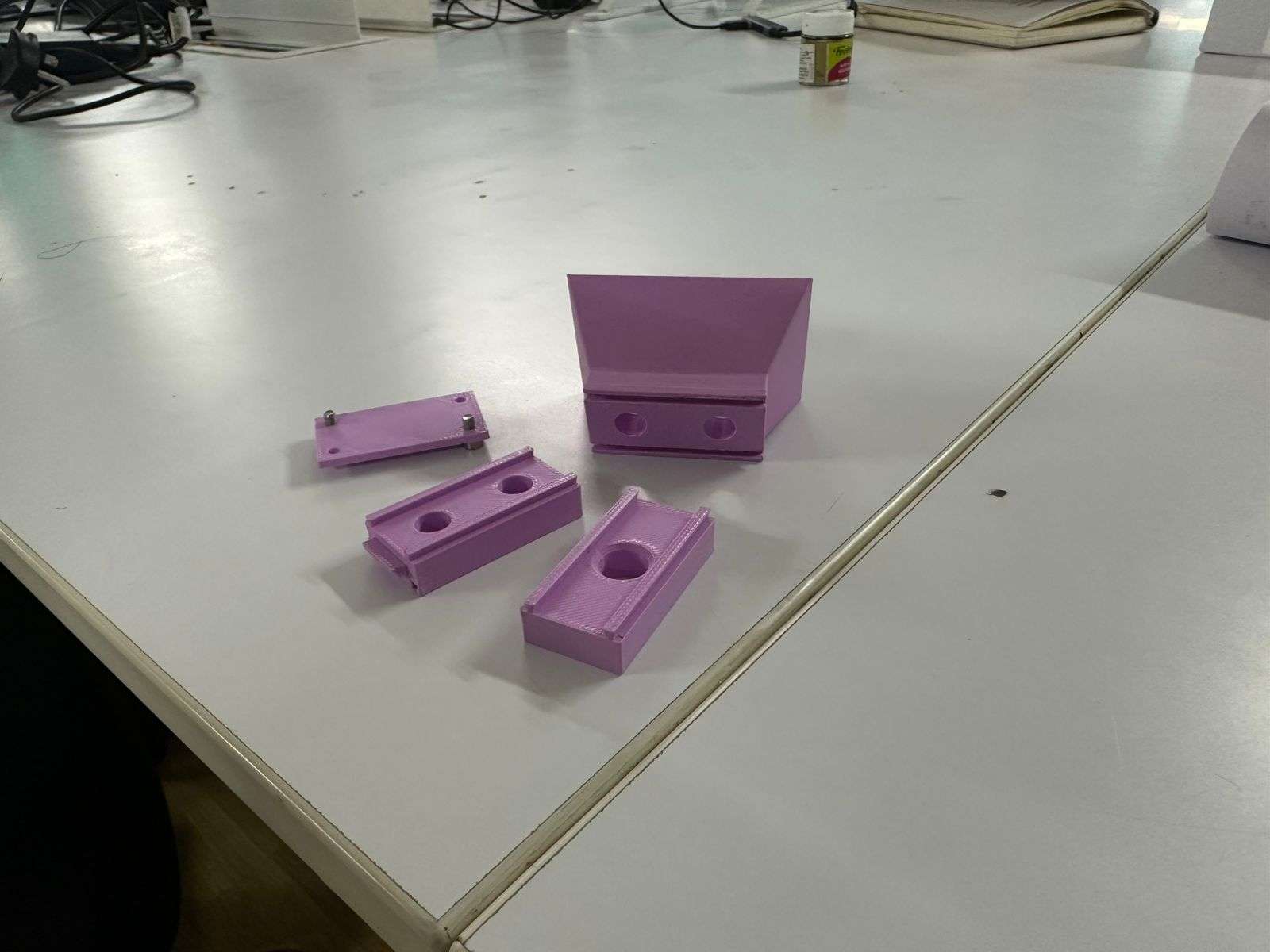
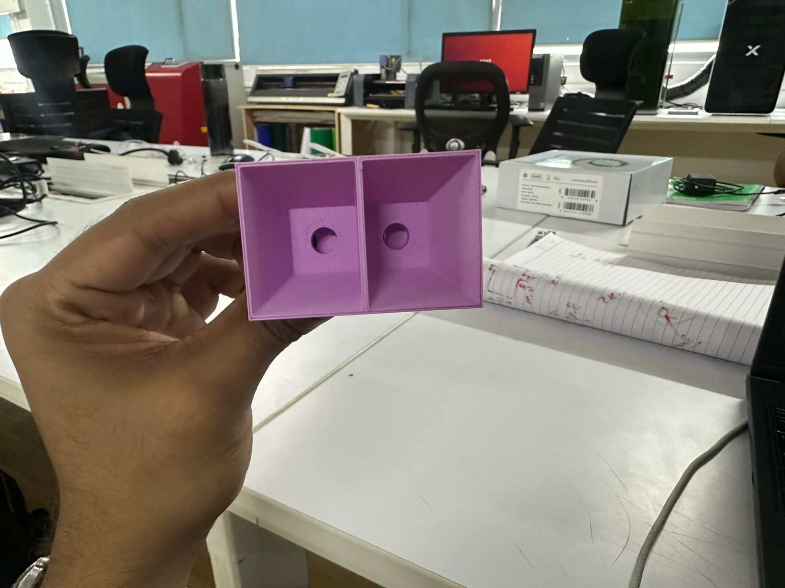
The prototype consisted of four parts. A bucket funnel with a separating wall dividing black and white bead channels, a slider whose height matched a single bead, a dispensing layer containing one large hole, and a backplate that held all components together.
I implemented a dovetail extrusion as the sliding mechanism.
Once fully assembled, several problems became apparent. The structure lacked stability, the bead height tolerances were inaccurate which caused inconsistent dispensing, and the dovetail slider did not move as smoothly as expected. Despite these shortcomings, the prototype successfully demonstrated that the fundamental concept worked.
Another issue was that the region around the funnel remained flat, allowing beads to accumulate and interrupt flow. Using these observations, I began a redesign.
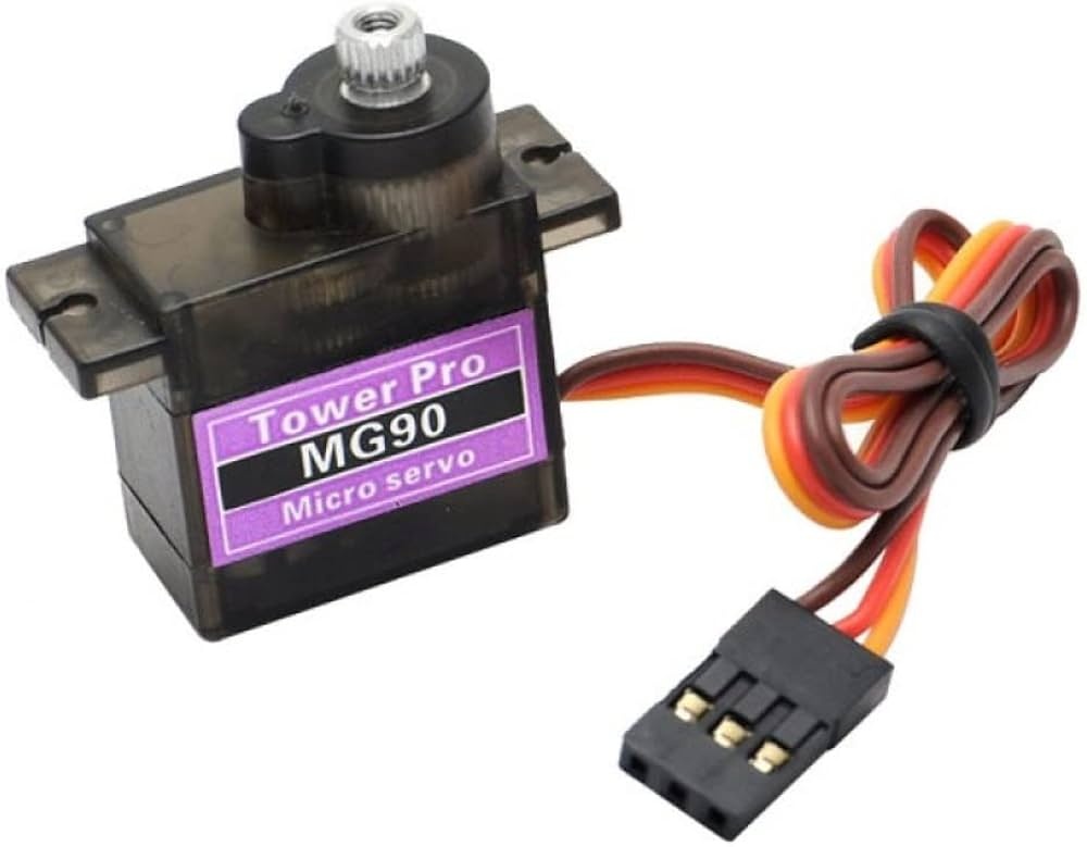
I also needed a method to actuate the slider. I decided to use a 180 degree servo motor, specifically the MG90S.
Initially, I considered using a scotch yoke mechanism to convert the servo rotation into linear slider motion.
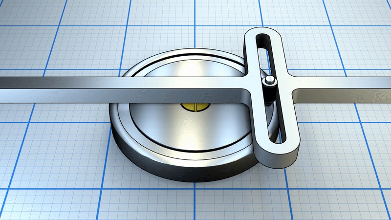
However, due to concerns regarding mechanical complexity and iteration time within the project deadline, I shifted to a rack and pinion mechanism. This approach appeared more suitable for controlled linear motion and required fewer experimental iterations.
Using an online gear generator https://evolventdesign.com/pages/spur-gear-generator, I generated a rack and pinion profile and exported the DXF file.
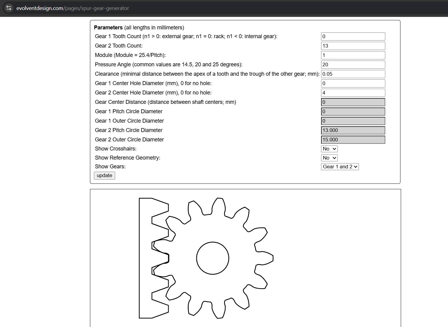
I extruded the profile, integrated it into the slider design, and added an accommodation for mounting the servo motor.
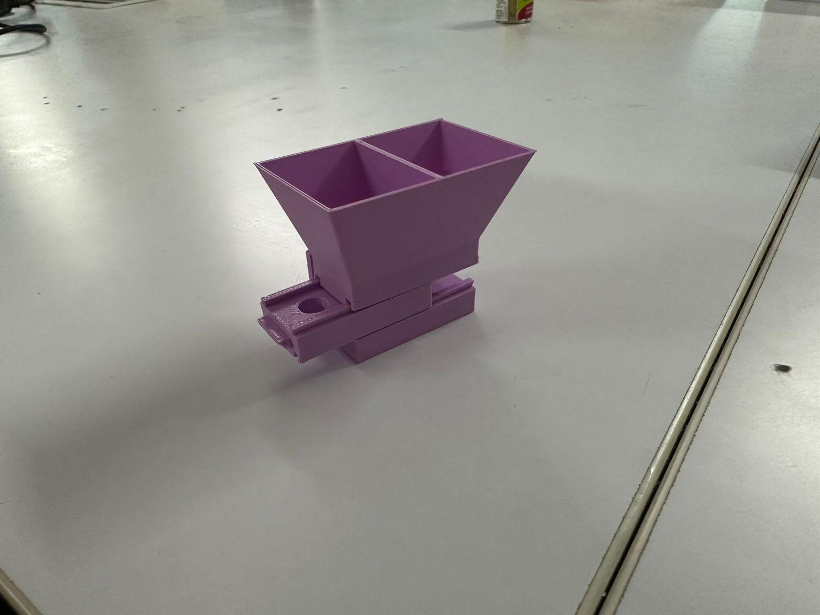
The resulting design was as follows.
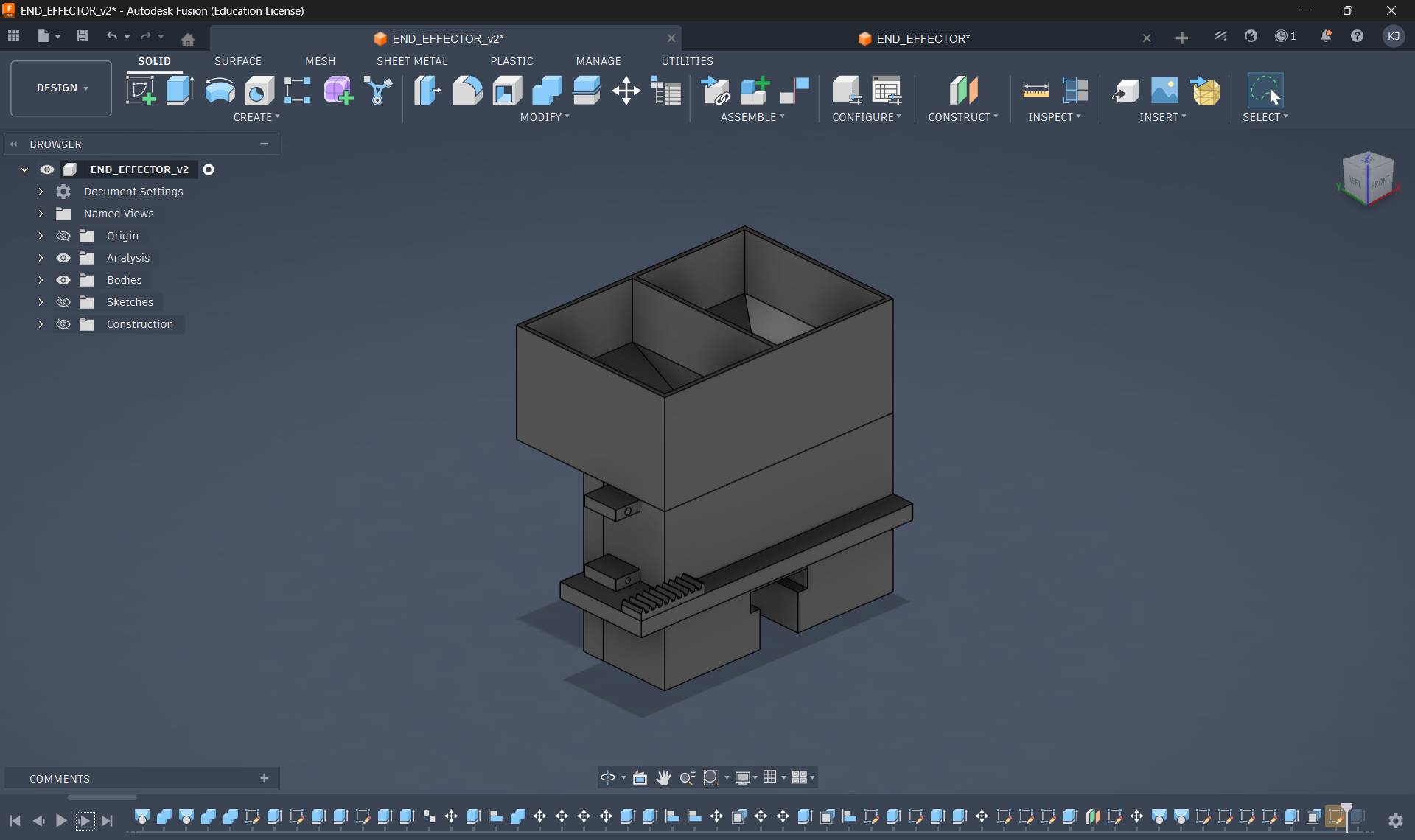
All parts except the bucket were printed. The bucket was intentionally made wide because I planned to match its dimensions to the gantry width. The opening at the bottom was left adjustable to accommodate a nozzle since the final drop height had not yet been determined.
This version also introduced several issues. The dovetail joint again performed poorly because it was undersized and effectively behaved like a loose track. Excess material was used without providing structural benefit. Nevertheless, once the servo was attached, the mechanism functioned and beads could be dispensed successfully.
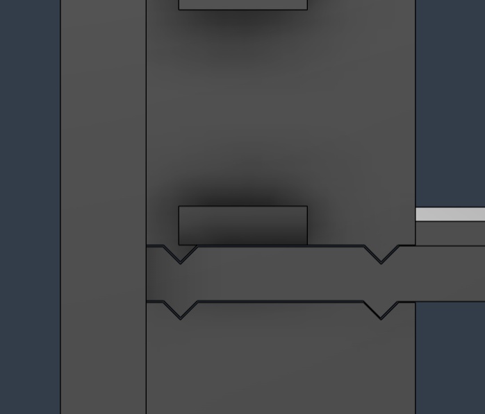
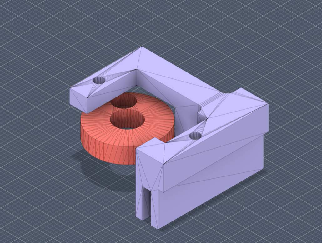
During the redesign, I replaced the sliding joint with a triangular extrusion.
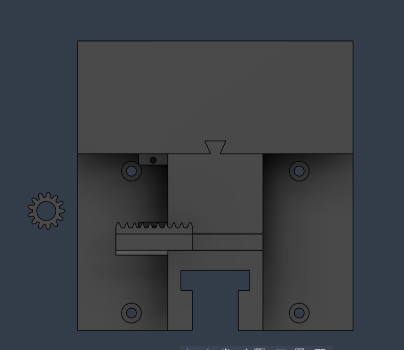
Previously, the backplate existed as a separate component, which meant the slider was not properly clamped. This introduced excessive tolerance and caused the pinion gear to skip teeth during motion. To address this, I redesigned the top, bottom, and backplate as a single integrated component while increasing the backplate thickness for rigidity.
Another limitation was that the earlier end effector depended on mounting holes from the gantry and could not function as an independent module. The redesign aimed to create a standalone end effector assembly.
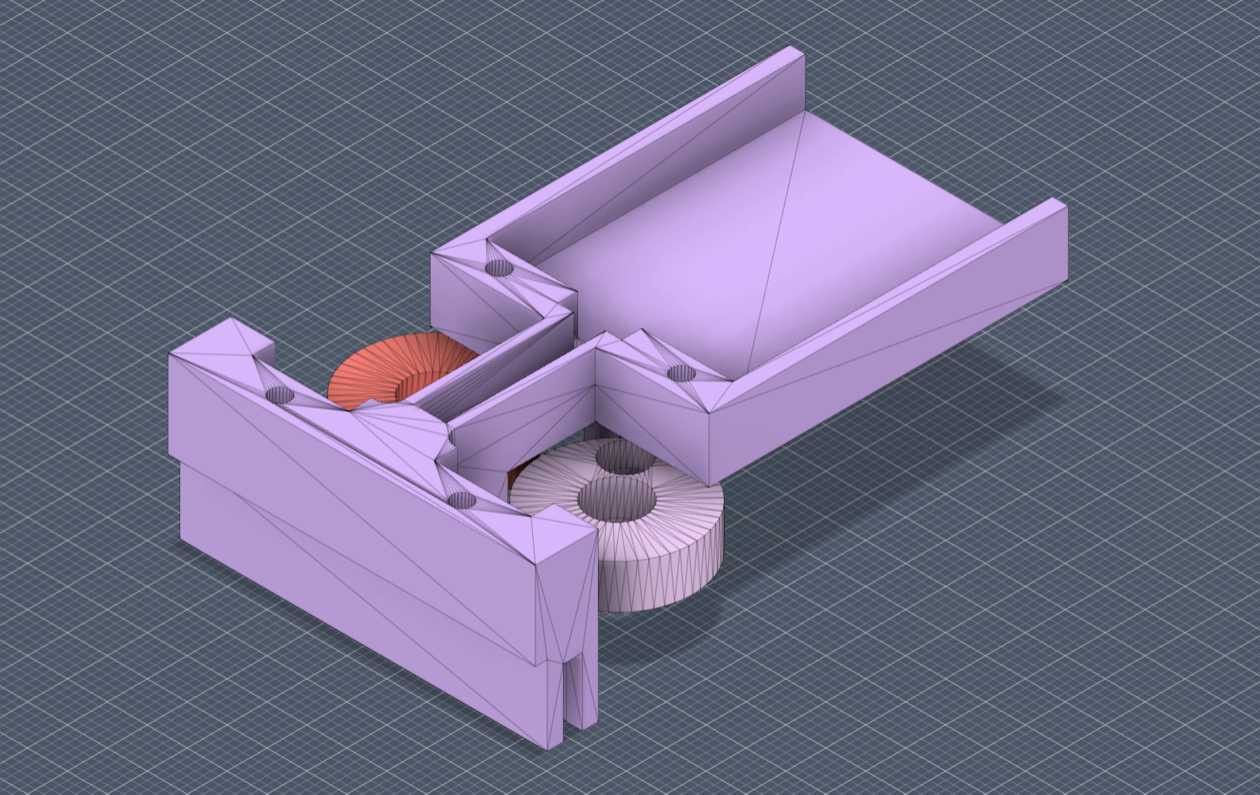
The new design resulted in significantly smoother motion while also reducing material usage and prioritizing the bead dispensing region.
I also introduced a dovetail joint for the bucket, allowing it to slide in and be removed easily for refilling or maintenance.
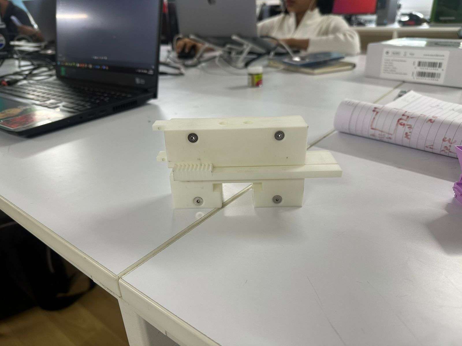
A first integrated prototype model was produced.
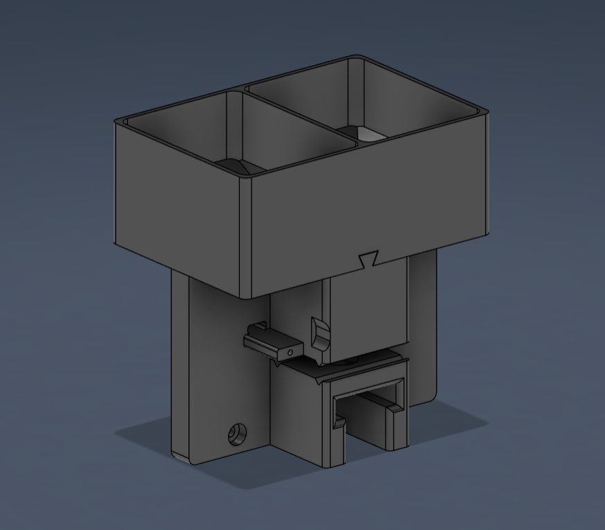
The slider mechanism worked reliably during testing, but a major issue appeared in the bucket hopper. At some point in the funnel geometry, the width becomes exactly two beads wide. At this location, beads jammed and stopped flowing. This phenomenon is known as hopper clogging.
After researching possible solutions, I determined that an agitator was required to maintain continuous bead flow.
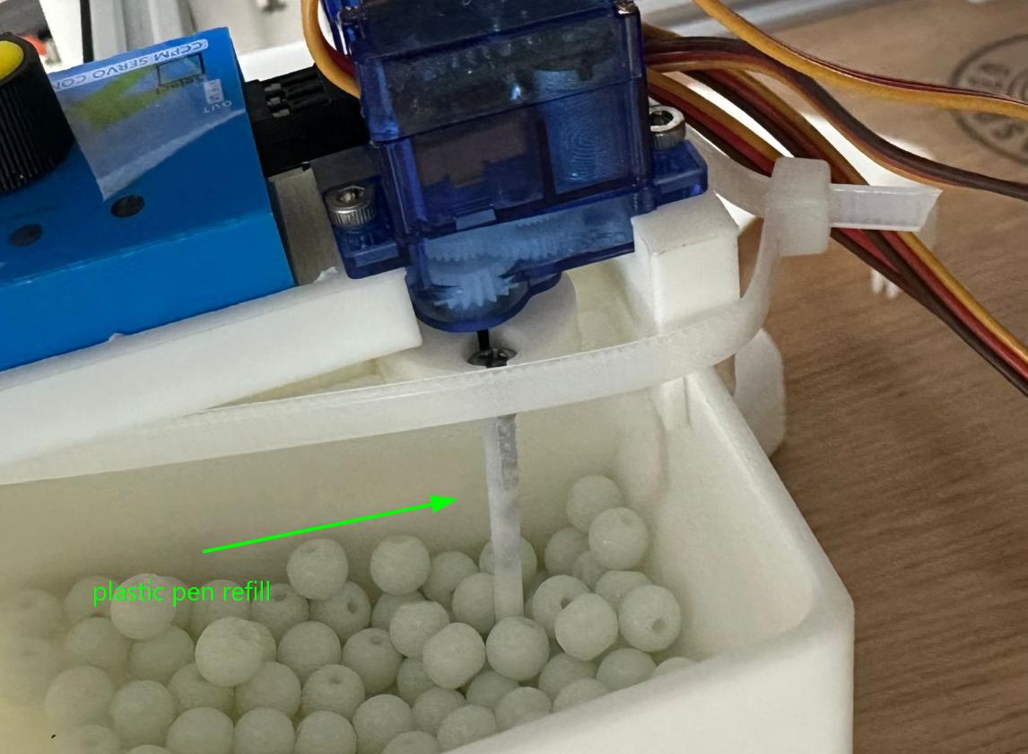
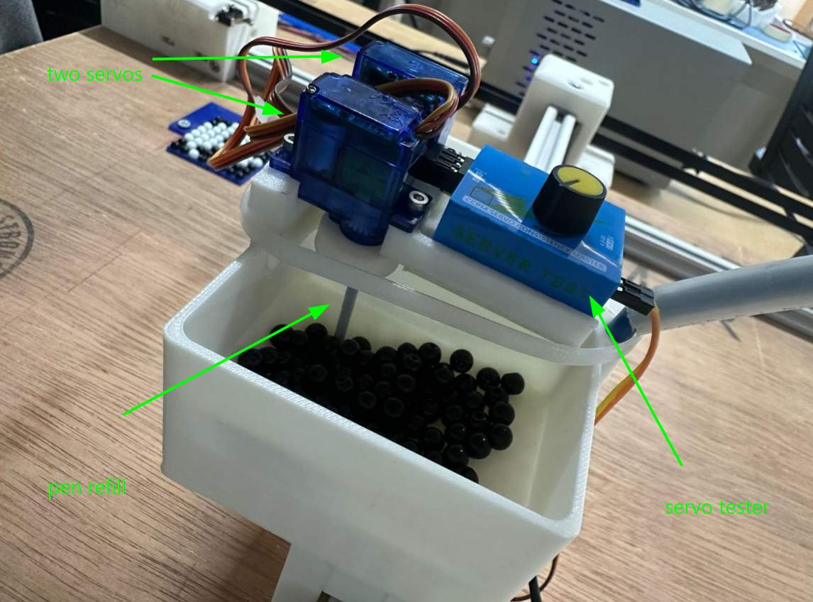
Through experimentation, I discovered that rotating a pen refill around the drop hole prevented clogging and allowed beads to flow consistently.
Given the approaching deadline, I implemented a practical solution. I added two servos positioned above the funnel drop holes. Each servo rotated a screw positioned close to the hole, continuously disturbing the bead packing similar to the pen refill experiment.
I first printed a small test assembly that held a single servo and a joint designed to mount an M3 40 mm screw.
This worked, so I completed the design and printed both sides.
To simplify electronics integration, I used an existing servo testing board capable of controlling rotation speed. I designed a mounting location for this board instead of developing a dedicated control board for the agitator servos.
During extended testing, the rigidity of the metal screws became a failure point. Beads occasionally became trapped between the screw and the wall, causing the servo to stall. Additionally, the agitation sometimes launched beads outward in a popcorn like manner.
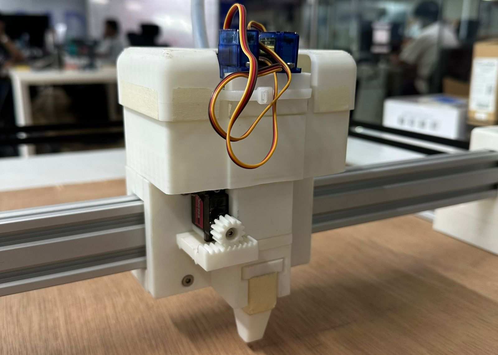
Two rapid solutions were implemented. Since pen refills had previously worked well, I replaced the metal screws with trimmed plastic pen refill tubes. Their semi flexible structure allowed them to deform slightly instead of jamming when beads became trapped. To prevent beads from ejecting outward, I designed an enclosing case around the funnel.
This enclosure also served as a mounting structure for the servo testing board.
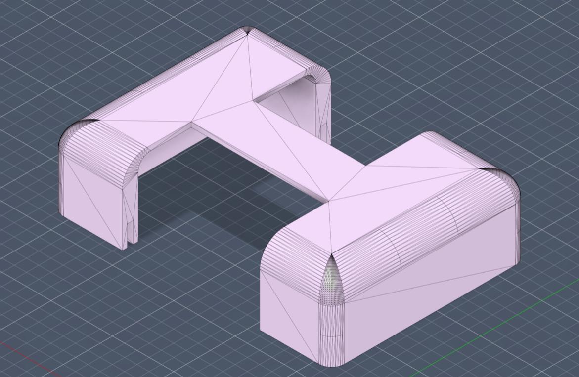
The bead mixer assembly resulted in the following configuration.
With the case installed, the completed end effector assembly appeared as follows.
After final integration and testing, the system successfully dispensed beads to form the letter R.
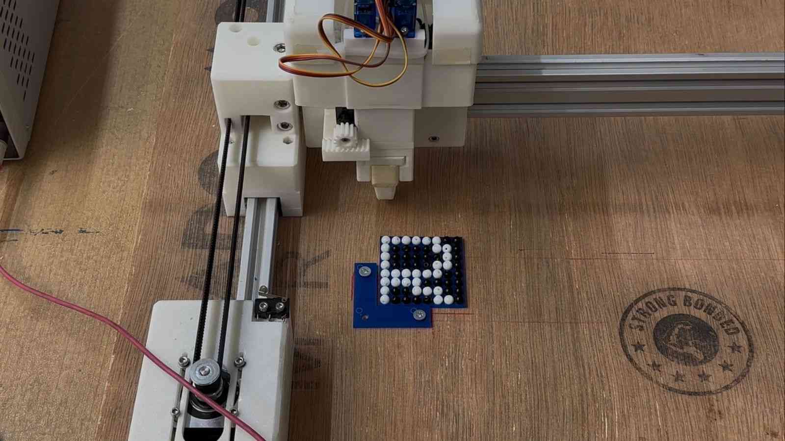
A video of the end effector in action can be found below. It's dispensing beads to form the letter P.