Individual Assignment
I was not able to complete my Networking and Communications Week assignment in time so i ended up doing this after my final project.I2C Communication Protocol
I2C (Inter-Integrated Circuit) is a serial communication bus protocol commonly used for short-distance data exchange between integrated circuits. It is also known as the Two-Wire Interface (TWI).
I2C uses only two bi-directional, open-drain lines:
SDA (Serial Data) – carries the actual data
SCL (Serial Clock) – carries the clock signal
Both SDA and SCL lines are normally pulled high using pull-up resistors. All devices on the bus are active low, meaning they can pull the lines low but not drive them high.
 (communication timing diagrams)
I2C supports two operating roles:
- Master mode
- Student mode
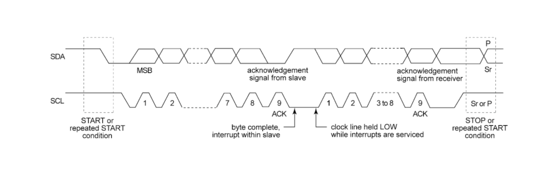
Every bit of data sent on the SDA line is synchronized with the clock on the SCL line. According to the I2C specification:
The data line (SDA) must remain stable while the clock line (SCL) is high.
SDA is only allowed to change state when SCL is low.
Data Format Data is transmitted in packets, typically consisting of 9 bits:
Start Condition – 1 bit
Student Address – 8 bits
Acknowledge (ACK) – 1 bit
Why I chose I2C
Before settling on I2C I thought about the two other options I could have used — SPI and UART. Here's why I2C fit this assignment best:
- Number of wires: I2C needs only two shared lines (SDA and SCL) no matter how many devices I add. SPI would have needed a separate chip-select wire to every single node, and my whole point was one master talking to multiple nodes on a shared bus.
- Addressing built in: each node has its own address (0x12, 0x13), so the master can talk to all of them or one specific node without extra wiring. That's exactly what my gesture control relies on — same touchpad, different address depending on the gesture. UART is point-to-point, so it can't do this cleanly with three boards.
- Multiple devices on one bus: I2C is designed for several chips sharing the same two lines, which is precisely my one-master-two-node setup. It made adding Abhishek's hub trivial — every port just ties SDA to SDA and SCL to SCL.
- Distance and speed were not a concern: my boards sit right next to each other and I'm only sending single bytes, so I didn't need SPI's higher speed. The trade-off (I2C is slower) simply didn't matter here.
In short, I2C's shared two-wire bus with addressing matched a project that is fundamentally "one board tells several other boards what to do," so it was the natural pick.
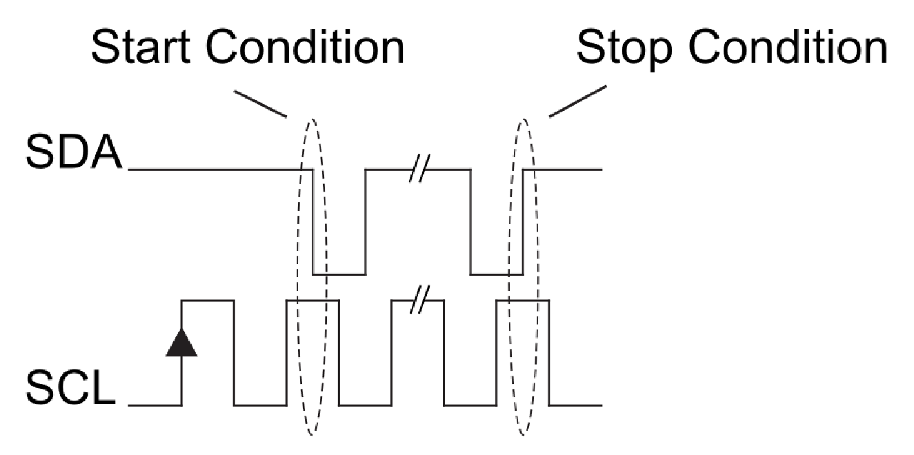
Start and Stop ConditionsStart and stop conditions are generated by changing SDA while SCL is kept high:
Start Condition: SDA goes from high to low while SCL is high.
Stop Condition: SDA goes from low to high while SCL is high.
 Read/Write Bit
A single Read/Write (R/W) bit indicates the direction of data transfer:
A high R/W bit means the master is sending data to the slave (write).
A low R/W bit means the master is receiving data from the slave (read).
Overall, this simple two-wire design, combined with addressing and start/stop conditions, allows multiple devices to share the same bus efficiently.
Designing the Board
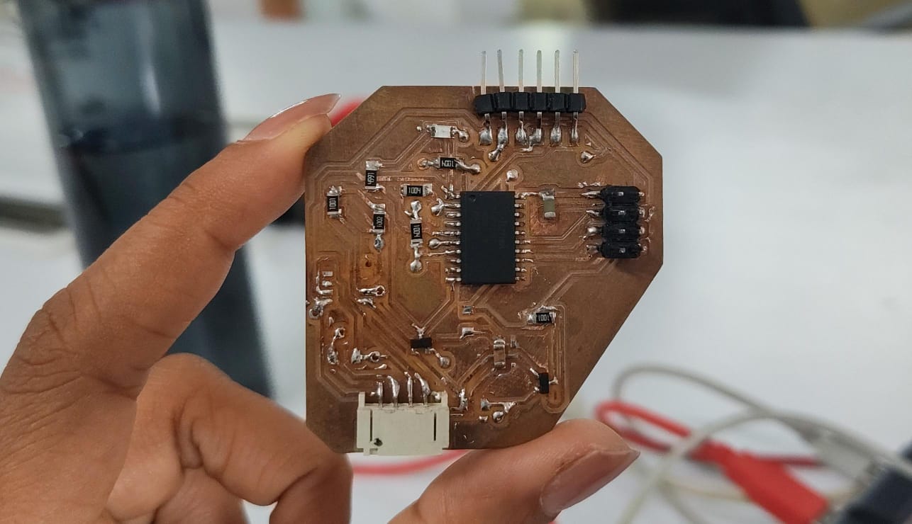
Master Board - reads touch and sendsFor the Master board , I'll be using the board developed during the the input week, which has an ATtiny3216 microcontroller,This board features a magnetic encoder and touch pads, along with along with the I2C pins.
Here i used the capacitive touch code that already worked on my previous board. The way it senses touch is a little trick, it discharges the pad LOW, then lets the pin float as an input and counts how long it takes to read back. A finger adds capacitance and changes that count, so when the delta drops past a threshold, it's a touch.
Once it knows the pad is touched, it sends a single byte to both node addresses. I only send on a change of state, so the bus isn't getting spammed every loop.
 Nodes — listening
Each node joins the bus as a peripheral with Wire.begin(address) and registers a callback. When the master sends a byte, it reads and sets the LED ON/OFF. The main loop just reflects that state onto the pins. Nothing fancy, the whole point of a node is to sit there and react.
Node 1
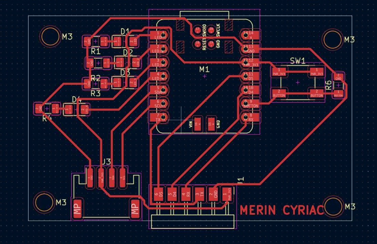
For Student Board 1, I will be using the board developed during my Electronics Design Week, its a simple LED board with a button.
 Node 2
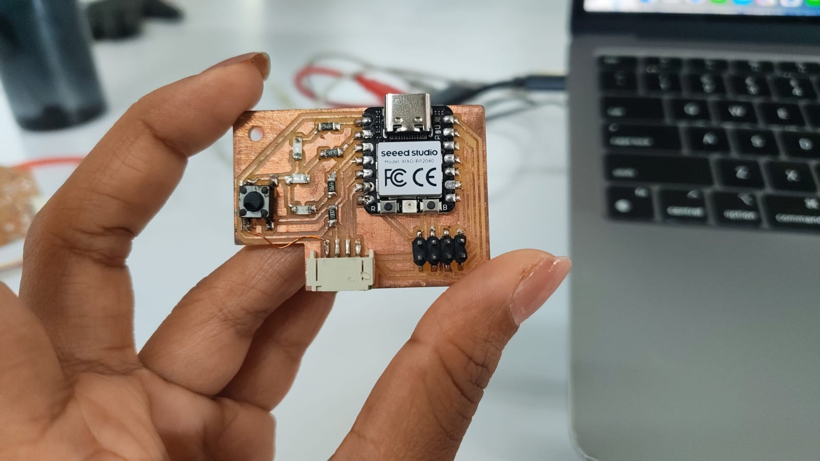
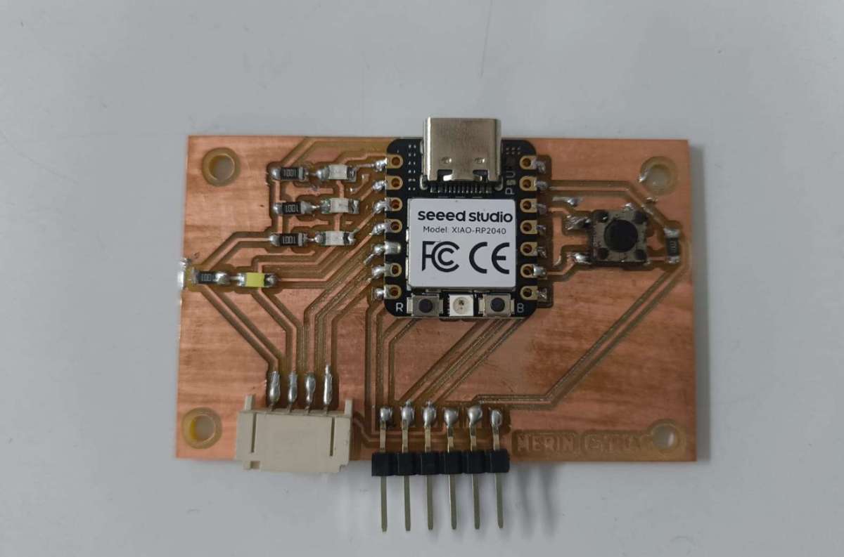
For Student Board 1, I used a fellow classmate's - Merin's board, developed during her Electronics Production Week
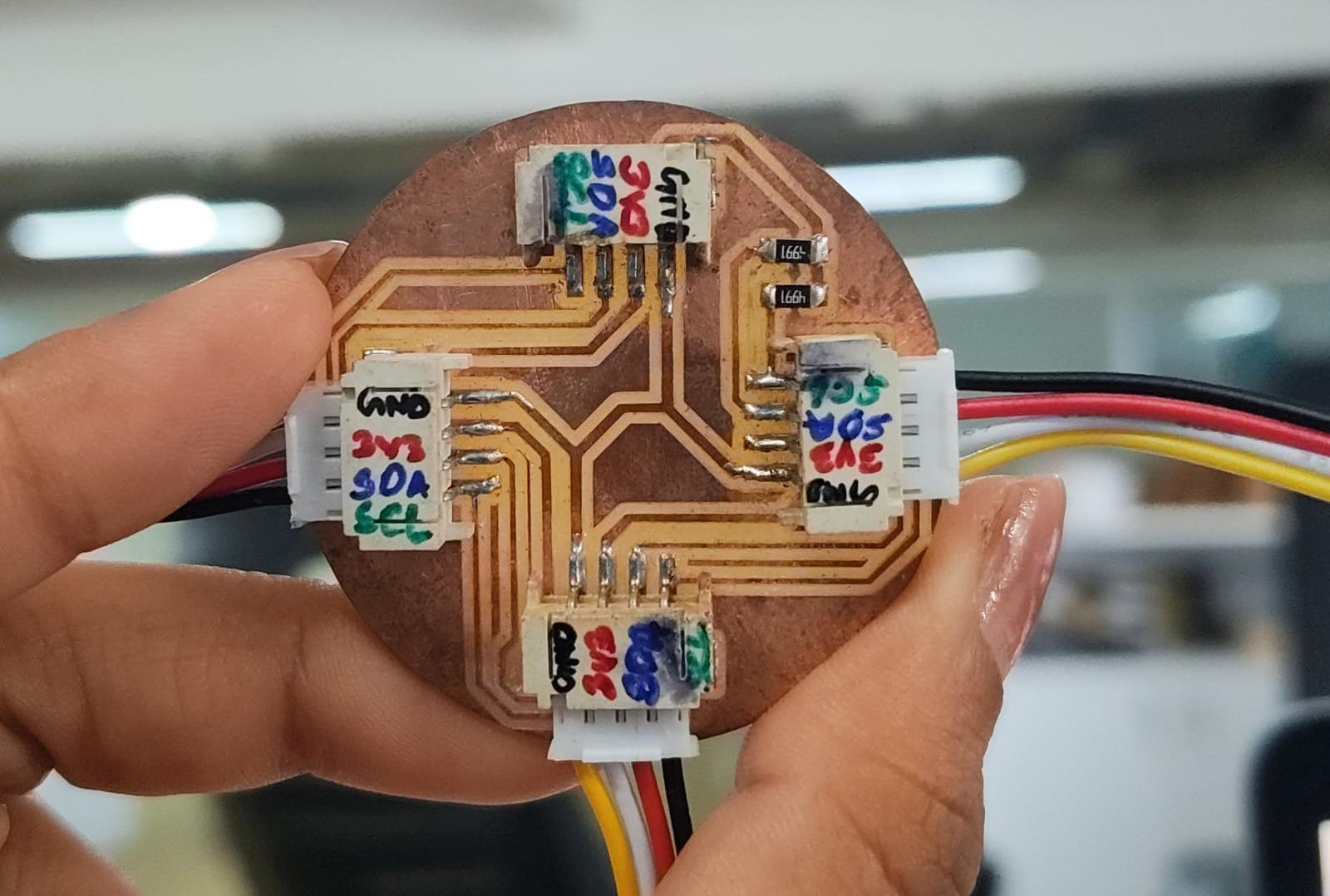
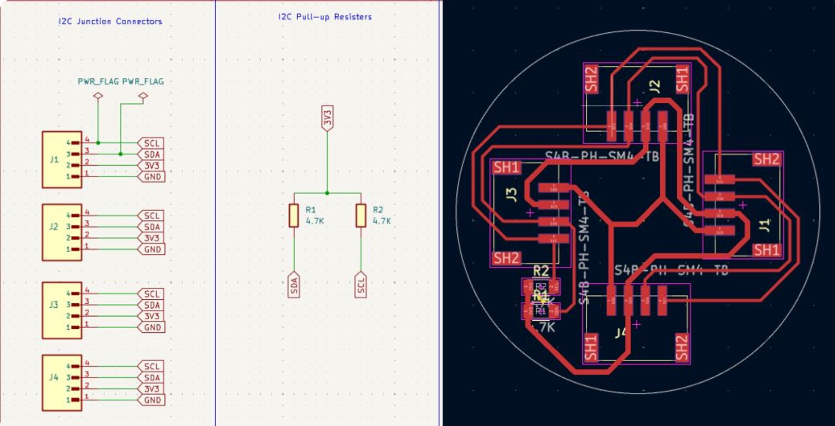
 For connecting multiple I2C nodes i used abhishek's I2C hub which he had made in the Networking and Communication Week where every connector ties SDA to SDA, SCL to SCL, and shares power and ground in parallel.
Programming the boards
For programming i referred a couple of documentations from the past academy graduates, Angelina Yang , Arduino's example.The master is the ATtiny, node 1 is at address 0x12 and node 2 is at 0x13.
To check whether nodes are seen
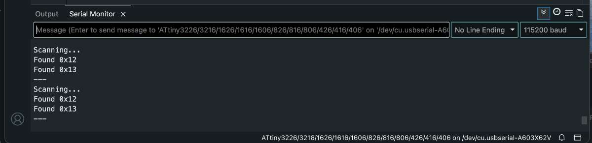
First, i started by checking whether the nodes can be seen by the master board, so i used an I2C scanner:#includevoid setup() { Serial.begin(115200); Wire.begin(); } void loop() { Serial.println("Scanning..."); int found = 0; for (uint8_t a = 1; a < 127; a++) { Wire.beginTransmission(a); if (Wire.endTransmission() == 0) { Serial.print("Found 0x"); Serial.println(a, HEX); found++; } } if (!found) Serial.println("No devices found"); Serial.println("---"); delay(2000); }
Prompt: Give an I2C Scanner Code to check for nodes.
An I2C scanner is where the master goes through every possible address from 1 to 126, tries to start a transmission to each one, and checks whether anything sends back signal. If a node is alive on the bus and listening at its address, the scanner prints it. If nothing answers, you know the node isn't reachable or somethings wrong with the wiring.
I flashed the code onto the master and watched the serial monitor and for the longest time i got the output as "No device found" so after checking every line with the multimeter i figured out that there was no power going to the XIAO, nodes, so i powered one node and both Xiaos lit up. Once i gave the XIAO its own power the scanner started picking it
 12C Addressing
The master side reused the capacitive touch code that already worked on my board,i.e, it sends a single byte, 0x01 for on, 0x00 for off ,to both node addresses. I only send on a change of state, so the bus isn't getting spammed every loop.
void sendCmd(uint8_t cmd) {
  if (cmd == lastSent) return;          // only transmit on state change
  sendTo(NODE1_ADDR, cmd);              // node 1 (single LED)
  sendTo(NODE2_ADDR, cmd);              // node 2 (4 LEDs)
  lastSent = cmd;
}
Each node joins the bus as a peripheral with Wire.begin and registers an onReceive callback. When the master sends a byte, the callback fires, reads it, and sets the LED state.
#define CMD_LED_ON 0x01
#define CMD_LED_OFF 0x00
volatile bool ledState = false;
// Called automatically when the ATtiny sends a byte to us.
void onReceive(int howMany) {
while (Wire.available()) {
uint8_t cmd = Wire.read();
if (cmd == CMD_LED_ON) ledState = true;
else if (cmd == CMD_LED_OFF) ledState = false;
}
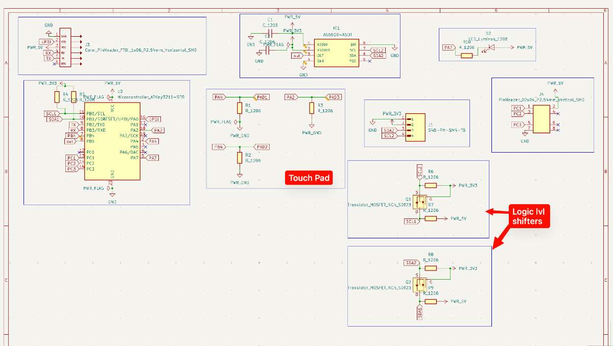
}System / Block Diagram
Before wiring anything up, here's the overall shape of my network — one master reading the touchpad and sending commands over a shared two-wire I2C bus to two nodes, each of which lights an LED.
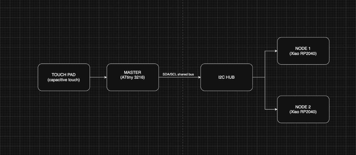 The ATtiny3216 master reads the capacitive touch pad, and on a change of state it puts a single byte
onto the shared I2C bus. Both XIAO RP2040 nodes sit on that same two-wire bus through Abhishek's hub (which
also carries the pull-ups, power and ground in parallel). Each node listens at its own address — 0x12 and
0x13 — and drives its LED when addressed.
The ATtiny3216 master reads the capacitive touch pad, and on a change of state it puts a single byte
onto the shared I2C bus. Both XIAO RP2040 nodes sit on that same two-wire bus through Abhishek's hub (which
also carries the pull-ups, power and ground in parallel). Each node listens at its own address — 0x12 and
0x13 — and drives its LED when addressed.
Master Code
/* * Communication Week - ATtiny3216 board (I2C CONTROLLER / MASTER) * ---------------------------------------------------------------- * Reads the capacitive touch pad and sends a 1-byte command over I2C * to BOTH XIAO nodes: * Node 1 (0x12) -> lights its single LED * Node 2 (0x13) -> lights its 4 LEDs * while the pad is touched. * * Touch sensing = Archie's proven method (finger LOWERS the count, * so delta goes NEGATIVE on touch). * * Board pin mapping (Output_week.kicad_sch): * Touch pad PAD1 -> PA4 * I2C SDA -> PB1 * I2C SCL -> PB0 * Local LED -> PB5 (optional feedback) * * Bus: ATtiny + node1(0x12) + node2(0x13) on the 4-port I2C hub, * SDA<->SDA, SCL<->SCL, GND<->GND common, pull-ups on the bus. * * Toolchain: Arduino IDE + megaTinyCore. Board: ATtiny3216, Wire host. * Don't touch the pad during the startup calibration. */ #include// ---- Pins ---- #define TOUCH_PIN PIN_PA4 #define LOCAL_LED PIN_PB5 // ---- Touch tuning (proven values) ---- #define NUM_SAMPLES 10 #define DELTA_THRESH 40 // touch when delta drops BELOW -DELTA_THRESH #define DRIFT_SPEED 0.02f // ---- I2C: both node addresses ---- #define NODE1_ADDR 0x12 //address of node1 #define NODE2_ADDR 0x13 //address of node2 #define CMD_LED_ON 0x01 #define CMD_LED_OFF 0x00 float baseline = 0; uint8_t lastSent = 0xFF; // force first transmit long measureOnce() { long count = 0; pinMode(TOUCH_PIN, OUTPUT); digitalWrite(TOUCH_PIN, LOW); delayMicroseconds(10); pinMode(TOUCH_PIN, INPUT); while (digitalRead(TOUCH_PIN) == LOW && count < 5000) count++; return count; } float measureAvg() { long total = 0; for (int i = 0; i < NUM_SAMPLES; i++) { total += measureOnce(); delayMicroseconds(200); } return (float)total / NUM_SAMPLES; } void sendTo(uint8_t addr, uint8_t cmd) { Wire.beginTransmission(addr); Wire.write(cmd); Wire.endTransmission(); } void sendCmd(uint8_t cmd) { if (cmd == lastSent) return; // only transmit on state change sendTo(NODE1_ADDR, cmd); // node 1 (single LED) sendTo(NODE2_ADDR, cmd); // node 2 (4 LEDs) lastSent = cmd; } void setup() { Serial.begin(115200); pinMode(LOCAL_LED, OUTPUT); digitalWrite(LOCAL_LED, LOW); Wire.begin(); Wire.setClock(100000); delay(500); // Calibration (no finger on the pad) long cal = 0; for (int i = 0; i < 50; i++) { cal += measureOnce(); delay(10); } baseline = (float)cal / 50.0f; } void loop() { float reading = measureAvg(); float delta = reading - baseline; // Serial Plotter: reading | baseline | delta Serial.print(reading); Serial.print(' '); Serial.print(baseline); Serial.print(' '); Serial.println(delta); bool touched = (delta < -DELTA_THRESH); digitalWrite(LOCAL_LED, touched ? HIGH : LOW); // local feedback sendCmd(touched ? CMD_LED_ON : CMD_LED_OFF); // tell both nodes // Drift correction only when not touched if (!touched) { baseline = baseline + (reading - baseline) * DRIFT_SPEED; } delay(50); }
Node 1
* * Communication Week - XIAO RP2040 board (I2C PERIPHERAL) * --------------------------------------------------------------- * Listens on I2C. When the ATtiny board reports its touch pad is * pressed, it lights the on-board LED. Releases -> LED off. * * Board pin mapping (from Xiao2040cp.kicad_sch): * LED net -> D2 (GPIO28) * I2C SDA -> D4 (GPIO6) -- XIAO hardware Wire (I2C1) * I2C SCL -> D5 (GPIO7) * * WIRING TO ATtiny BOARD: * XIAO D4 (SDA) <-> ATtiny PB1 (SDA) * XIAO D5 (SCL) <-> ATtiny PB0 (SCL) * XIAO GND <-> ATtiny GND * (4.7k pull-ups from SDA/SCL to 3V3 if not present on a board.) * * Toolchain: Arduino IDE + "Raspberry Pi Pico/RP2040" core (Earle Philhower) * Board: "Seeed Studio XIAO RP2040" * * On the Philhower core, Wire is already mapped to D4/D5, so a plain * Wire.begin(addr) works. We set it explicitly for clarity. */ #include#define I2C_ADDR 0x12 // must match XIAO_ADDR in the ATtiny sketch #define LED_PIN D2 // schematic LED net -> D2 (GPIO28) #define CMD_LED_ON 0x01 #define CMD_LED_OFF 0x00 volatile bool ledState = false; // Called automatically when the ATtiny sends a byte to us. void onReceive(int howMany) { while (Wire.available()) { uint8_t cmd = Wire.read(); if (cmd == CMD_LED_ON) ledState = true; else if (cmd == CMD_LED_OFF) ledState = false; } } void setup() { pinMode(LED_PIN, OUTPUT); digitalWrite(LED_PIN, LOW); Wire.setSDA(D4); Wire.setSCL(D5); Wire.begin(I2C_ADDR); // join bus as peripheral with this address Wire.onReceive(onReceive); } void loop() { // The ISR sets ledState; we just reflect it on the pin. digitalWrite(LED_PIN, ledState ? HIGH : LOW); delay(5); }
Node 2
/* * Communication Week - XIAO RP2040 board (I2C PERIPHERAL / SLAVE) * --------------------------------------------------------------- * Listens on I2C. When the ATtiny board reports its touch pad is * pressed, it lights the on-board LED. Releases -> LED off. * * Board pin mapping (from Xiao2040cp.kicad_sch): * LED net -> D2 (GPIO28) * I2C SDA -> D4 (GPIO6) -- XIAO hardware Wire (I2C1) * I2C SCL -> D5 (GPIO7) * * WIRING TO ATtiny BOARD: * XIAO D4 (SDA) <-> ATtiny PB1 (SDA) * XIAO D5 (SCL) <-> ATtiny PB0 (SCL) * XIAO GND <-> ATtiny GND * (4.7k pull-ups from SDA/SCL to 3V3 if not present on a board.) * * Toolchain: Arduino IDE + "Raspberry Pi Pico/RP2040" core (Earle Philhower) * Board: "Seeed Studio XIAO RP2040" * * On the Philhower core, Wire is already mapped to D4/D5, so a plain * Wire.begin(addr) works. We set it explicitly for clarity. */ #include#define I2C_ADDR 0x13 // must match XIAO_ADDR in the ATtiny sketch #define LED_PIN D2 // schematic LED net -> D2 (GPIO28) #define CMD_LED_ON 0x01 #define CMD_LED_OFF 0x00 volatile bool ledState = false; // Called automatically when the ATtiny sends a byte to us. void onReceive(int howMany) { while (Wire.available()) { uint8_t cmd = Wire.read(); if (cmd == CMD_LED_ON) ledState = true; else if (cmd == CMD_LED_OFF) ledState = false; } } void setup() { pinMode(LED_PIN, OUTPUT); digitalWrite(LED_PIN, LOW); Wire.setSDA(D4); Wire.setSCL(D5); Wire.begin(I2C_ADDR); // join bus as peripheral with this address Wire.onReceive(onReceive); } void loop() { // The ISR sets ledState; we just reflect it on the pin. digitalWrite(LED_PIN, ledState ? HIGH : LOW); delay(5); }
Talking to nodes individually — gesture control
Once the basic one master two nodes setup was working, I wanted to actually address each node separately from a single touchpad :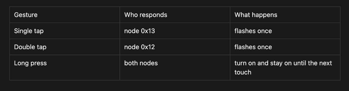 This is where I2C addressing actually earns its keep. In the first version the master just send the same byte to both address. Here the master has to decide which address to talk to, so the same pad can trigger three completely different outcomes depending on the gesture.
How it happens?
The touchpad only tells if its touched or not touched. A tap, a double tap and a long press all start out identical. The only way to tell them apart is timing, how long the touch lasts, and whether a second touch follows quickly. So the master measures time.When a touch starts, it times how long my finger stays down. If it's held longer than a threshold (i used 600 ms), that's a long press, decides immediately on release.
unsigned long held = waitForRelease();   // how long was it held?

if (held >= LONG_PRESS_MS) {
  doLongPress();   // both nodes ON
  return;
}
If the press was short, it can't decide yet — because a single tap and the first half of a double tap look exactly the same. So after the finger lifts, it waits a short window (350 ms) to see if a second tap arrives. If one does, it's a double tap. If the window passes with nothing, it was a single tap.
// short press: wait briefly to see if a SECOND tap comes
unsigned long gapStart = millis();
bool second = false;
while (millis() - gapStart < DOUBLE_GAP_MS) {
  if (isTouched()) { second = true; break; }
}

if (second) { waitForRelease(); doDoubleTap(); }  // 0x12
else        { doSingleTap(); }                    // 0x13
12C Addressing
Talking to NodesThe actual communication part is simple once the gesture is known, it's just which address the master opens a transmission to:
void sendTo(uint8_t addr, uint8_t cmd) {
  Wire.beginTransmission(addr);
  Wire.write(cmd);
  Wire.endTransmission();
}
Message conveyed:
  void doSingleTap() { sendTo(0x13, CMD_FLASH); }   // only node 2 hears this
void doDoubleTap() { sendTo(0x12, CMD_FLASH); }   // only node 1 hears this
void doLongPress() {
  sendTo(0x12, CMD_ON);
  sendTo(0x13, CMD_ON);
}
Each node sits on the bus waiting. You register a callback with Wire.onReceive(), and the moment the master sends something to that node's address, the callback fires automatically.
void onReceive(int howMany) {
  while (Wire.available()) {
    uint8_t cmd = Wire.read();
    if      (cmd == CMD_OFF)   { ledOn = false; }
    else if (cmd == CMD_ON)    { ledOn = true;  }
    else if (cmd == CMD_FLASH) { flashReq = true; }
  }
}
node is assigned its own unique address:
Addressing on Node 1
#define I2C_ADDR 0x12
Addressing on Node 1
#define I2C_ADDR 0x13
Master Code
/* * Communication Week - ATtiny3216 MASTER with gesture control * ----------------------------------------------------------- * Reads the capacitive touch pad, classifies the gesture, and sends a * TARGETED command to individual nodes: * * Single tap -> node 0x13 flashes once * Double tap -> node 0x12 flashes once * Long press -> both nodes latch ON, stay on until the next touch * (next touch of any kind turns everything OFF) * * Touch sensing = proven method (finger LOWERS the count, delta goes * NEGATIVE on touch). * * Pins (Output_week.kicad_sch): pad PA4, SDA PB1, SCL PB0. * Bus: ATtiny + 0x12 + 0x13 on the I2C hub, shared GND + pull-ups. * Toolchain: Arduino IDE + megaTinyCore. Don't touch pad during calibration. * * NOTE: the optional on-board feedback LED (PB5) was removed because this * ATtiny3216 variant doesn't expose PIN_PB5 in megaTinyCore. */ #include// ---- Pins ---- #define TOUCH_PIN PIN_PA4 // ---- Touch tuning ---- #define NUM_SAMPLES 10 #define DELTA_THRESH 40 #define DRIFT_SPEED 0.02f // ---- Gesture timing (milliseconds) ---- #define LONG_PRESS_MS 600 // held longer than this = long press #define DOUBLE_GAP_MS 350 // 2nd tap must start within this after release #define DEBOUNCE_MS 30 // ---- I2C ---- #define NODE1_ADDR 0x12 // double tap #define NODE2_ADDR 0x13 // single tap #define CMD_OFF 0x00 #define CMD_ON 0x01 #define CMD_FLASH 0x02 float baseline = 0; bool latchedOn = false; // are nodes currently held ON by a long press? void sendTo(uint8_t addr, uint8_t cmd) { Wire.beginTransmission(addr); Wire.write(cmd); Wire.endTransmission(); } long measureOnce() { long count = 0; pinMode(TOUCH_PIN, OUTPUT); digitalWrite(TOUCH_PIN, LOW); delayMicroseconds(10); pinMode(TOUCH_PIN, INPUT); while (digitalRead(TOUCH_PIN) == LOW && count < 5000) count++; return count; } float measureAvg() { long total = 0; for (int i = 0; i < NUM_SAMPLES; i++) { total += measureOnce(); delayMicroseconds(200); } return (float)total / NUM_SAMPLES; } bool isTouched() { float reading = measureAvg(); float delta = reading - baseline; bool touched = (delta < -DELTA_THRESH); if (!touched) baseline += (reading - baseline) * DRIFT_SPEED; // drift only when idle return touched; } unsigned long waitForRelease() { unsigned long start = millis(); while (isTouched()) { /* hold */ } return millis() - start; } void doSingleTap() { sendTo(NODE2_ADDR, CMD_FLASH); } // 0x13 void doDoubleTap() { sendTo(NODE1_ADDR, CMD_FLASH); } // 0x12 void doLongPress() { sendTo(NODE1_ADDR, CMD_ON); sendTo(NODE2_ADDR, CMD_ON); latchedOn = true; } void clearLatch() { sendTo(NODE1_ADDR, CMD_OFF); sendTo(NODE2_ADDR, CMD_OFF); latchedOn = false; } void setup() { Serial.begin(115200); Wire.begin(); Wire.setClock(100000); delay(500); long cal = 0; for (int i = 0; i < 50; i++) { cal += measureOnce(); delay(10); } baseline = (float)cal / 50.0f; } void loop() { if (!isTouched()) { delay(10); return; } delay(DEBOUNCE_MS); unsigned long held = waitForRelease(); // length of first press // If nodes are latched on, ANY touch turns them off. if (latchedOn) { clearLatch(); delay(200); return; } if (held >= LONG_PRESS_MS) { doLongPress(); delay(200); return; } // Short press: watch for a second tap -> double tap unsigned long gapStart = millis(); bool second = false; while (millis() - gapStart < DOUBLE_GAP_MS) { if (isTouched()) { second = true; break; } } if (second) { delay(DEBOUNCE_MS); waitForRelease(); // consume second tap doDoubleTap(); // 0x12 } else { doSingleTap(); // 0x13 } delay(150); }
Prompt for Claude: If you want a shorter version for a tighter list: "Add gesture control to my ATtiny I2C master — single tap triggers node 0x13, double tap triggers node 0x12, long press latches both on until the next touch. Write the timing-based gesture detection and update the node sketches.
Node 1
/* * Communication Week - Node 1 (XIAO RP2040, addr 0x12) - gesture-aware * Commands from master: * 0x00 OFF -> LED off * 0x01 ON -> LED on and stays on (until 0x00) * 0x02 FLASH -> LED blinks once briefly, then off * LED on D2. I2C on D4(SDA)/D5(SCL). * Toolchain: Arduino IDE + "Raspberry Pi Pico/RP2040" core (Philhower). */ #include#define I2C_ADDR 0x12 #define LED_PIN D2 #define CMD_OFF 0x00 #define CMD_ON 0x01 #define CMD_FLASH 0x02 volatile bool ledOn = false; volatile bool flashReq = false; void onReceive(int howMany) { while (Wire.available()) { uint8_t cmd = Wire.read(); if (cmd == CMD_OFF) { ledOn = false; } else if (cmd == CMD_ON) { ledOn = true; } else if (cmd == CMD_FLASH) { flashReq = true; } } } void setup() { pinMode(LED_PIN, OUTPUT); digitalWrite(LED_PIN, LOW); Wire.setSDA(D4); Wire.setSCL(D5); Wire.begin(I2C_ADDR); Wire.onReceive(onReceive); } void loop() { if (flashReq) { flashReq = false; digitalWrite(LED_PIN, HIGH); delay(120); digitalWrite(LED_PIN, LOW); delay(120); } digitalWrite(LED_PIN, ledOn ? HIGH : LOW); delay(5); }
/* * Communication Week - Node 2 (XIAO RP2040, addr 0x13) - gesture-aware * Commands from master: * 0x00 OFF -> LED off * 0x01 ON -> LED on and stays on (until 0x00) * 0x02 FLASH -> LED blinks once briefly, then off * LED on D2. I2C on D4(SDA)/D5(SCL). * Toolchain: Arduino IDE + "Raspberry Pi Pico/RP2040" core (Philhower). */ #include#define I2C_ADDR 0x13 #define LED_PIN D2 #define CMD_OFF 0x00 #define CMD_ON 0x01 #define CMD_FLASH 0x02 volatile bool ledOn = false; volatile bool flashReq = false; void onReceive(int howMany) { while (Wire.available()) { uint8_t cmd = Wire.read(); if (cmd == CMD_OFF) { ledOn = false; } else if (cmd == CMD_ON) { ledOn = true; } else if (cmd == CMD_FLASH) { flashReq = true; } } } void setup() { pinMode(LED_PIN, OUTPUT); digitalWrite(LED_PIN, LOW); Wire.setSDA(D4); Wire.setSCL(D5); Wire.begin(I2C_ADDR); Wire.onReceive(onReceive); } void loop() { if (flashReq) { flashReq = false; digitalWrite(LED_PIN, HIGH); delay(120); digitalWrite(LED_PIN, LOW); delay(120); } digitalWrite(LED_PIN, ledOn ? HIGH : LOW); delay(5); }
Output
Conclusion
This week I got a full I2C network working , an ATtiny3216 master reading a capacitive touchpad and sending single-byte commands over a shared two-wire bus to two XIAO RP2040 nodes, first lighting both together and then addressing each one separately through tap, double-tap and long-press gestures. Getting there taught me that most of I2C is straightforward once the wiring and addresses are right; the tricky part is everything around it.
A few problems slowed me down, and each one left me with something worth remembering. For the longest time my scanner just printed "No devices found" after going over every line with a multimeter I realised there was no power reaching the XIAO at all. Once I powered a node properly, both XIAOs lit up and the scanner picked them up straight away. I also learned that I2C simply won't behave without pull-up resistors on SDA and SCL. On the software side, a node only ever responds if its address exactly matches what the master is transmitting to, so when one node worked and another stayed dark, the address mismatch was the first thing to check.
Group assignment
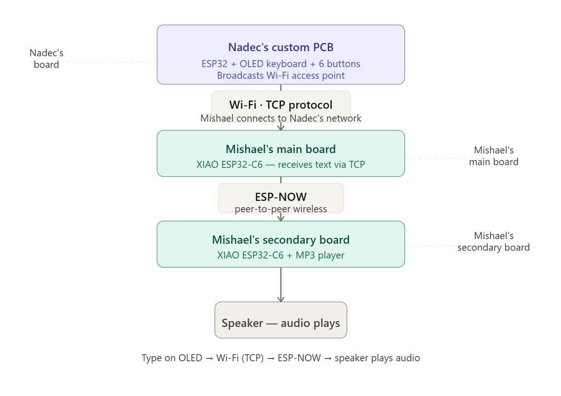
For the group side of this week we had to get communication going between two different people's boards. Nadec and Mishael built the demo.
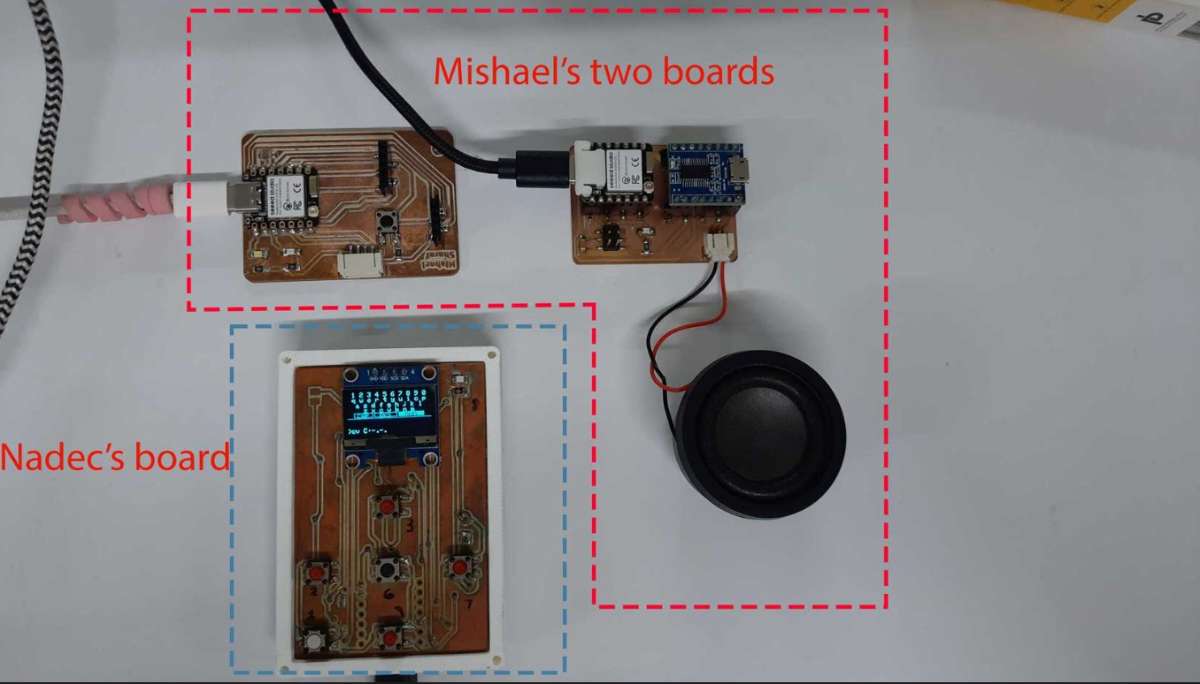 Nadec's ESP32 board with an OLED QWERTY keyboard acts as a Wi-Fi access point hosting a TCP server, and whatever you type on it gets sent over WiFi to Mishael's main XIAO ESP32-C6, which then relays it over ESP-NOW to a second board hooked up to an MP3 player and speaker.
So you type "hello" on one board and it comes out as audio on another going through Wi-Fi and ESP-NOW on the way.
Nadec's ESP32 board with an OLED QWERTY keyboard acts as a Wi-Fi access point hosting a TCP server, and whatever you type on it gets sent over WiFi to Mishael's main XIAO ESP32-C6, which then relays it over ESP-NOW to a second board hooked up to an MP3 player and speaker.
So you type "hello" on one board and it comes out as audio on another going through Wi-Fi and ESP-NOW on the way.
 (img)
(img)