Group assignment
For the group assignment we measured the power consumption of our output devices using a bench power supply and a digital multimeter. We tested two things: 3 WS2812B NeoPixels on a board we made earlier, and a stepper motor driven through a motor controller board. To read the current we put the multimeter in current mode and connected it in series with the supply, then powered everything from 5 V.
Click here for Group AssignmentHow the power of an output device is calculated
Electrical power is just voltage multiplied by current:
P = V × I (watts = volts × amps)
So we measured the voltage across the device and the current through it, then multiplied the two. From our measurements:
- NeoPixels: 5.0 V × 0.0337 A = 0.168 W
- Stepper motor: 5.0 V × 0.011 A = 0.055 W
Individual Assignment
The main objective for this week was to read and play music from an SD card, and control playback (forward/rewind/speed) based on the rotation of a physical disk. This mimics a DJ-style interaction, where the motion of a disk directly affects the music playback.At the beginning, I explored ready-made MP3 player modules such as the DX player. However, I found that:
It could only play / pause / skip tracks
It did not support variable speed playback
It could not rewind or scrub audio dynamically
Since my project requires real-time control of playback speed, this approach was not suitable. Next i searched about different amplifiers & modules.
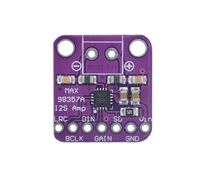
MAX98357A
 img
imgWhat is MAX98357A?
 source
It is a tiny chip/module that lets your microcontroller (like Arduino or ESP32) play sound through a speaker.Datasheet
source
It is a tiny chip/module that lets your microcontroller (like Arduino or ESP32) play sound through a speaker.Datasheet
It does two main jobs:
1. Converts digital audio → analog sound
Your ESP32 sends audio in a digital format called **I2S** (a special audio data format).
2. Amplifies the sound
The signal is too weak by itself, so the MAX98357A boosts it enough to drive a speaker directly.
(def ChatGPT: "Explain MAX98357A")
 source
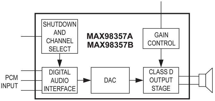
The Digital Audio Interface on the left is where the I2S signals (BCLK, LRC and DIN) come in from the ESP32. From there the signal goes to the DAC, which converts the digital audio into an actual analog waveform. That then feeds the Class D Output Stage, the part that amplifies it enough to drive the speaker directly.
The Shutdown and Channel Select decides whether the chip is awake or in low-power mode, and whether it plays the left, right, or mixed channel. Gain Control sets how loud the output is. Both of these are tied to the SD pin on the module.
What is I2S?
I2S (Inter-IC Sound) is a way for chips to send audio data to each other digitally.I'm using the MAX98357A I2S Class-D amplifier breakout module. Its key specs:
- Class-D output, up to about 3.2 W into a 4 Ω speaker
- Supply range roughly 2.5 V – 5.5 V (works fine off the XIAO 3.3–5 V)
- Digital I2S input (BCLK, LRC, DIN) — no analog audio needed
- Filterless design, so very few external parts
- Selectable gain and L/R/mix channel via the SD pin
How I2S works
I2S (Inter-IC Sound) carries digital audio on three lines that work together:
- BCLK (bit clock): ticks once for every bit of audio data, keeping both chips in step.
- LRC / WS (word select): a slower signal that flips between left and right — its level tells the receiver which channel the current sample belongs to.
- DIN (data): the actual audio sample bits, sent one at a time on each BCLK tick.
The ESP32 acts as the I2S master generating BCLK and LRC, and the MAX98357A is the student that reads the data and turns it into sound.
Why I chose the module, not the bare IC
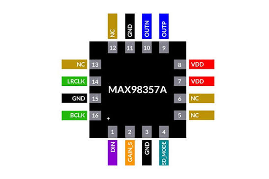
I picked the ready-made breakout module instead of the bare MAX98357A chip because the bare IC is a tiny QFN package that is very hard to hand-solder, and it needs its supporting passives (decoupling, speaker connection) laid out correctly. The module already has all of that done on a small board with throughhole pads, so I could wire it straight to my XIAO and focus on the firmware instead of fighting the soldering.
DC and Coreless motor
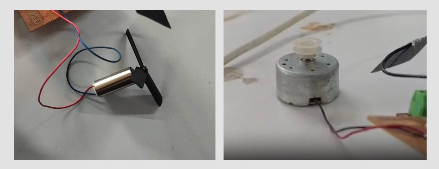
Since I need to rotate the disk like in a DJ set, I added a small motor. My instructor suggested a coreless motor that runs on 3.7 V — it is small, light and spins up quickly, which suits rotating the disk.But for this experiment i used the motor on the right which is a DC motor.
What is a coreless motor?
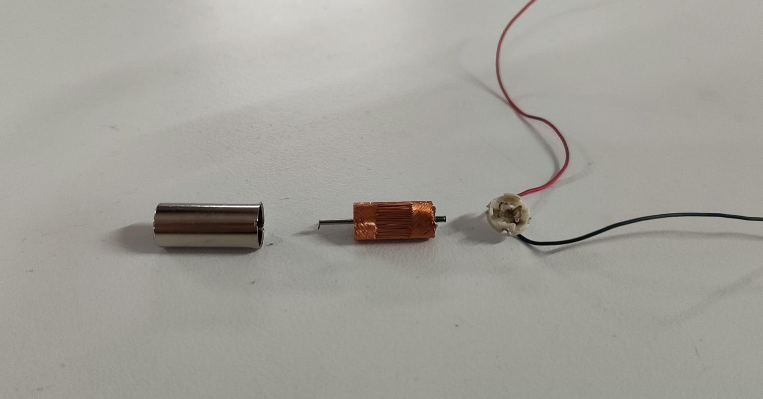 A normal DC motor(On the right) has copper windings wrapped around an
iron
core. A coreless motor leaves out the heavy iron core, the windings are self-supporting
so the
rotor is much lighter. That means it starts, stops and changes speed faster, with less vibration, which
is good
for responsive control.
A normal DC motor(On the right) has copper windings wrapped around an
iron
core. A coreless motor leaves out the heavy iron core, the windings are self-supporting
so the
rotor is much lighter. That means it starts, stops and changes speed faster, with less vibration, which
is good
for responsive control.
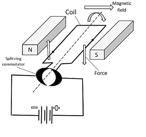
How does a DC motor works
 SOURCE
A DC motor turns electrical energy into rotation using magnetism. When current flows through the motor's coil, the coil becomes an electromagnet. This electromagnet is sitting between the poles of permanent magnets, so it gets pushed and pulled, that force makes the rotor spin. Reverse the supply polarity and it spins the other way, which is exactly why I need an H-bridge to control direction.
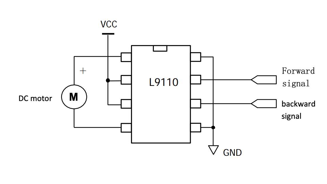
Single H bridge IC
What is IC? An IC (Integrated Circuit) is a tiny electronic circuit built into a small chip that can perform specific functions.What is a H-bridge and why do we need it?
An H-bridge is a circuit shaped like the letter “H”, made of switches (transistors inside the IC). It allows you to:
- Rotate a motor forward
- Rotate it backward
- Stop it
- Sometimes even brake it
A single bridge IC controls 1 motor while a double bridge motor controls 2.
How does it work?
Think of 4 switches:
- Turn ON one pair → motor spins forward
- Turn ON the opposite pair → motor spins reverse
- Turn OFF all → motor stops
The advantage of using an IC H Bridge is that these switches are handled for you inside the IC and you do not have to built the circuit piece by piece.
Here, i am using L9110, which i took from the module below
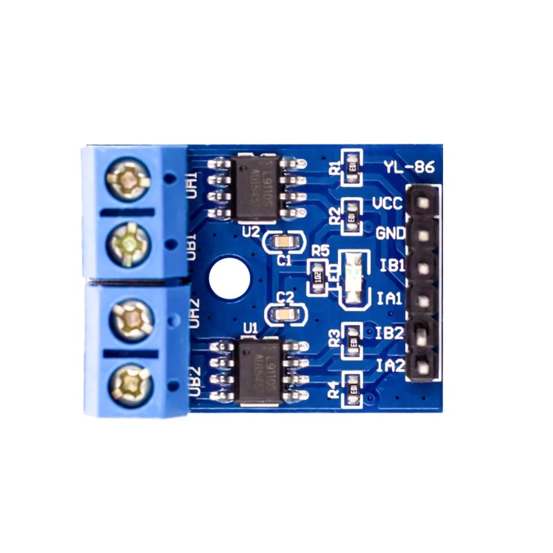 img
img
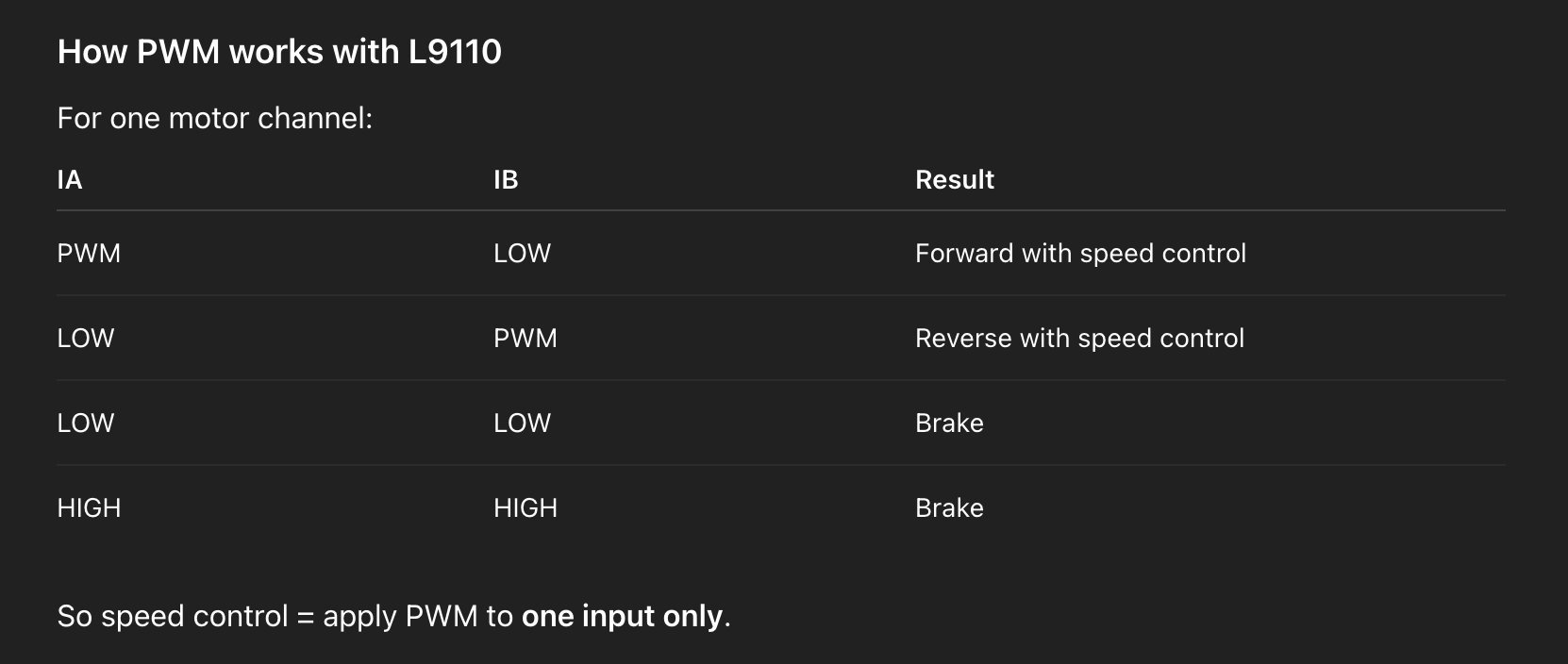
Now, after going through its datasheet we found out that it does not have any PWM pins, but can imitate it using it’s IA and IB pins as follows:
 source
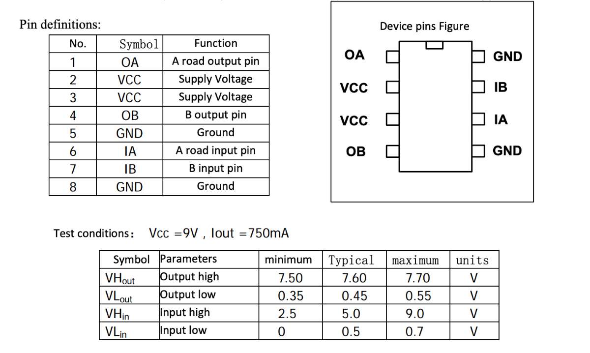
 AI prompt (ChatGPT): "Explain in simple terms what an H-bridge is, how it controls a
DC motor's
direction, and why an H-bridge IC is used instead of building it from individual transistors."
AI prompt (ChatGPT): "Explain in simple terms what an H-bridge is, how it controls a
DC motor's
direction, and why an H-bridge IC is used instead of building it from individual transistors."
XIAO ESP32S3 Sense
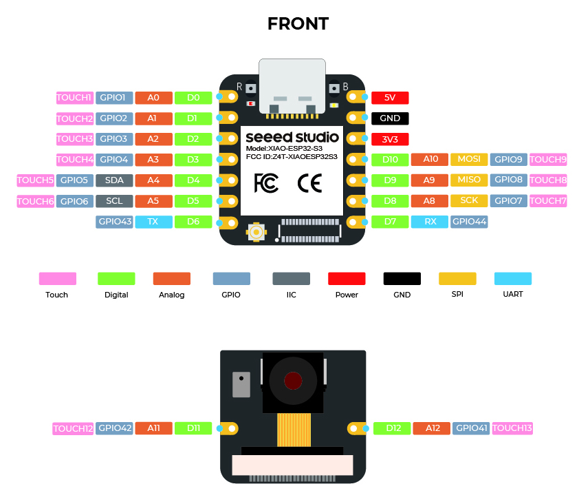 The ESP32-S3 has a dual-core 240MHz processor which is powerful enough to decode MP3 files in real time entirely in software. Simpler microcontrollers like ATtiny
or SAMD21 cannot do this they lack both the processing speed and RAM required. The main reason is that i comes with a mount on SDCard, and it's built-in I2S support,
which is the exact protocol my amplifier needs to receive.
The ESP32-S3 has a dual-core 240MHz processor which is powerful enough to decode MP3 files in real time entirely in software. Simpler microcontrollers like ATtiny
or SAMD21 cannot do this they lack both the processing speed and RAM required. The main reason is that i comes with a mount on SDCard, and it's built-in I2S support,
which is the exact protocol my amplifier needs to receive.SD cards and the XIAO ESP32-S3 Sense
An SD card is a small flash-memory storage card. It talks to a microcontroller over the
SPI bus (clock, MOSI, MISO and a chip-select line), and the files on it are read using a
FAT32 filesystem — the same format a computer understands, which is how I can copy audio
files onto the card from my laptop.
Click for the SD Card link.
The XIAO ESP32-S3 Sense is handy here because its little expansion/camera board has a built-in microSD card slot wired to the SPI pins. That means I can store my audio files on the card and stream them to the amplifier, without needing a separate SD module, one of the main reasons I chose this board for an audio project.
Diagrams
Next i drew the schematic diagram and the PCB diagram: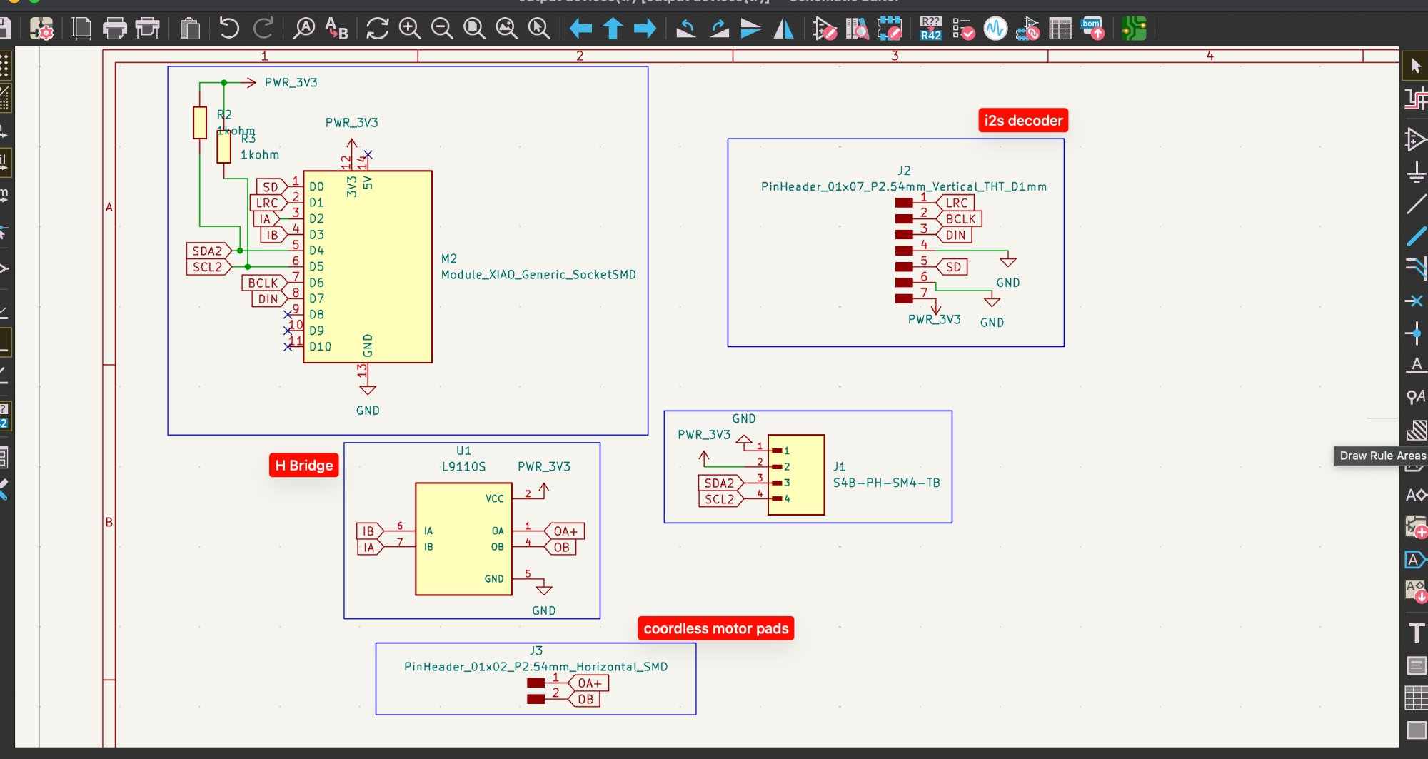
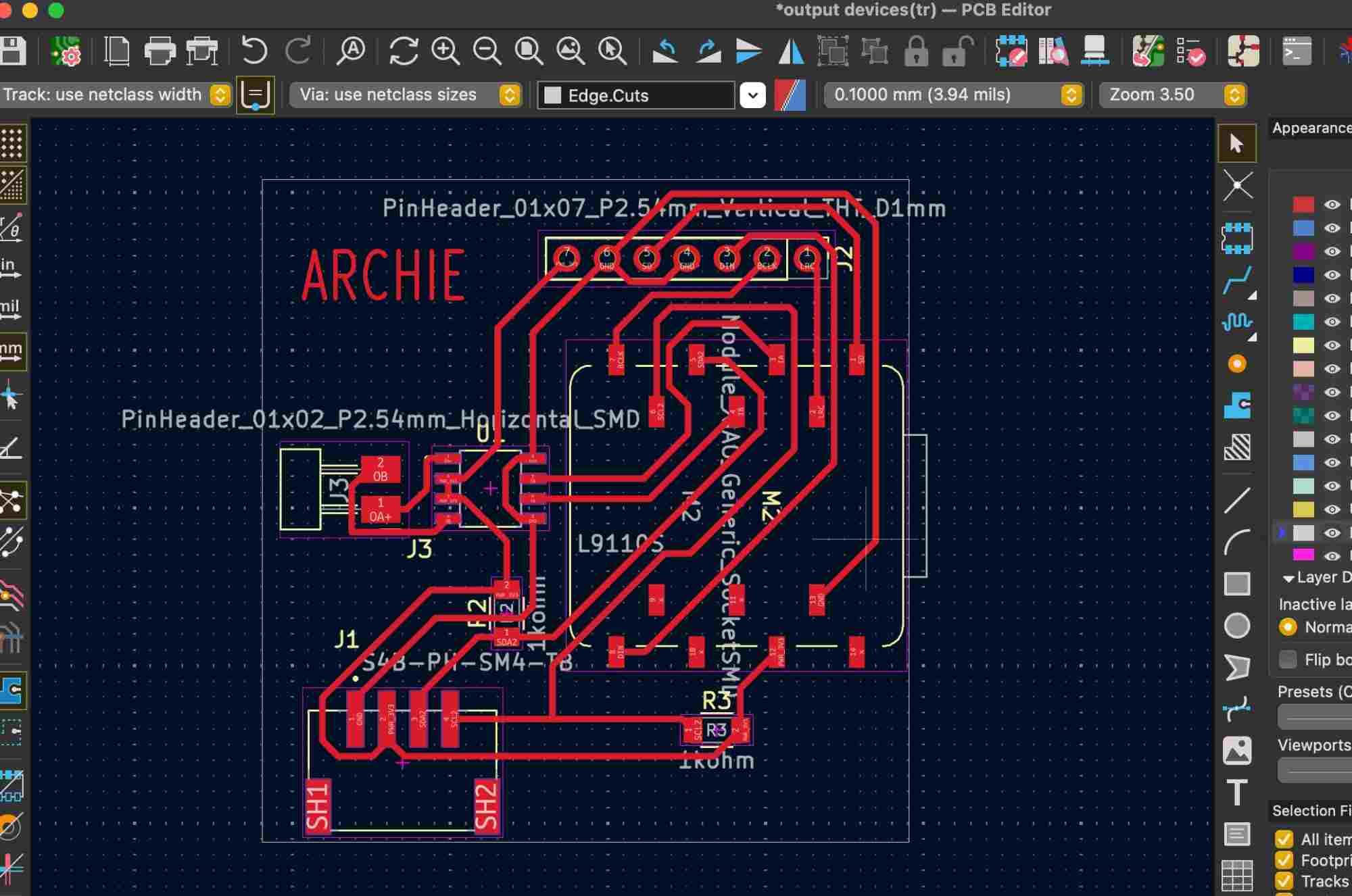 Then i milled the PCB, detailed explanation of the PCB production process is mentioned in Week8.
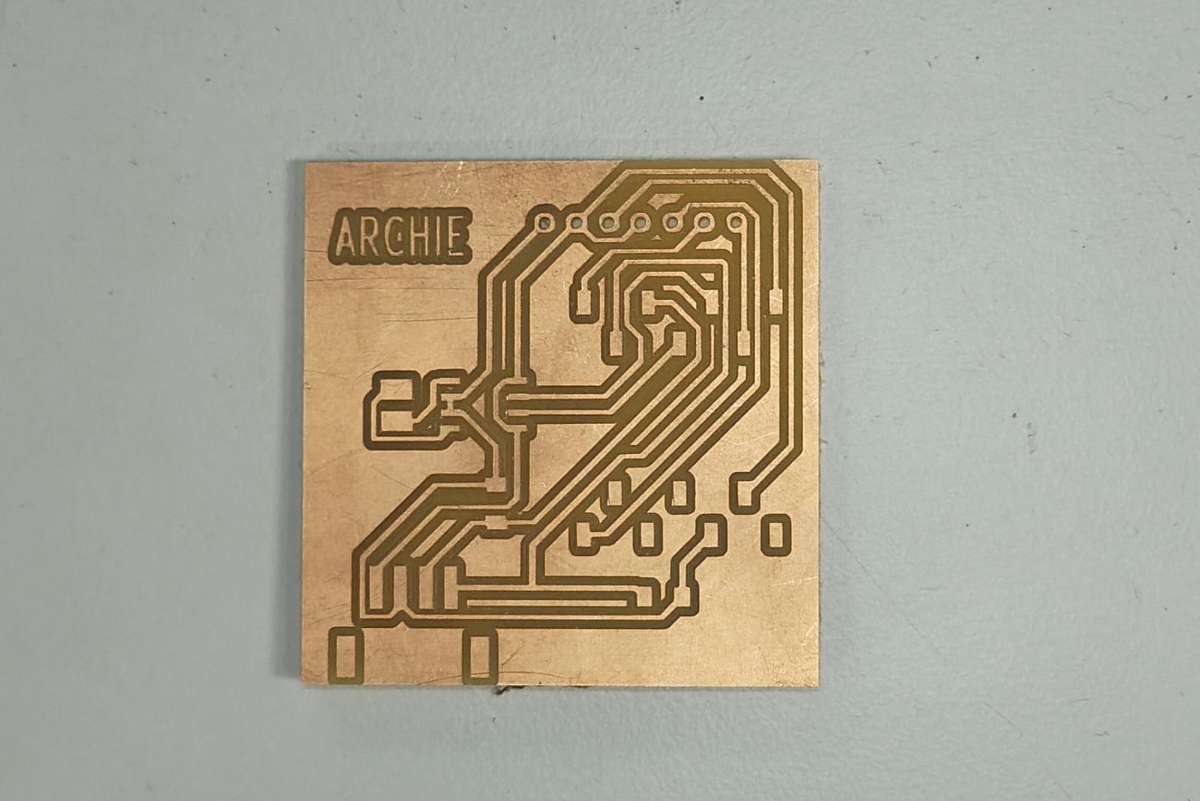
This is how the complete milled PCB looked :
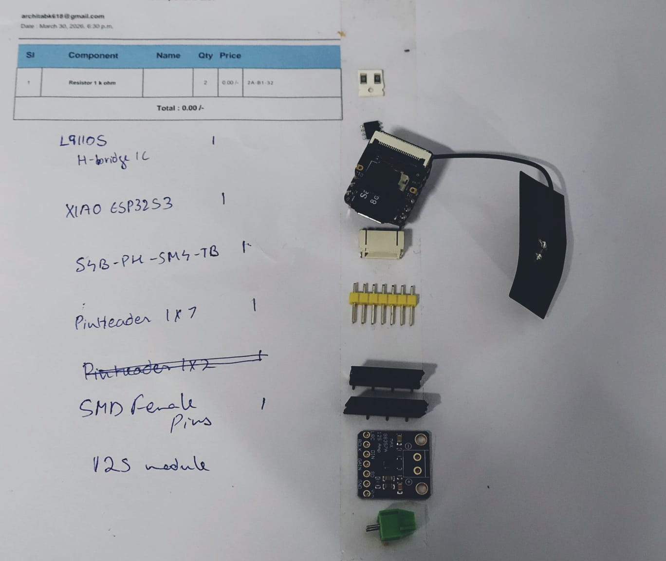
 Then i assembled the needed components
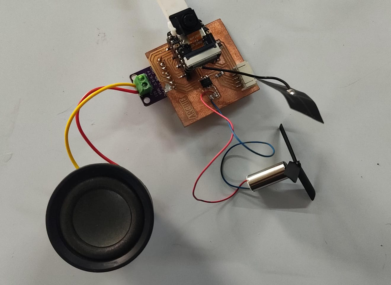
 and soldered the PCB(Hero shot)
Programming
Setting up the toolchain
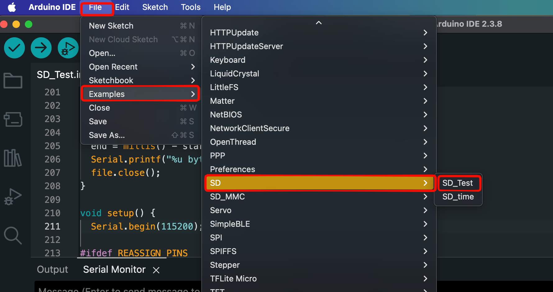
Before writing the code I set up the toolchain in the Arduino IDE. I added the ESP32 boards by putting the Espressif board-manager URL into File → Preferences → Additional Board Manager URLs , then installed the esp32 by Espressif Systems package from Tools → Board Manager. I selected XIAO_ESP32S3 as the board, enabled PSRAM, I also installed the audio library I used for playback.
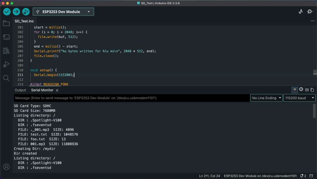
SD card and formatting
- I used a microSD card and formatted it as FAT32, because that's the filesystem the ESP32 SD library reads.
- Copied the prepared audio files onto the root of the card.
 I wasn't able to get it right eventhough my code was fine. most probably due to loose connection.
but in the end i got it right:
 I got from example code from
Seeed / Espressif I2S audio example for the ESP32-S3. then I worked through it with
ChatGPT, editing it heavily over several iterations:
I got from example code from
Seeed / Espressif I2S audio example for the ESP32-S3. then I worked through it with
ChatGPT, editing it heavily over several iterations:
Preparing the audio files
I prepared the audio on my laptop before copying it to the card:
- Took my source audio and converted it to the format my playback code expects (I used ffmpeg to re-encode the files so the bitrate/sample rate were consistent and small enough to stream smoothly).
- Kept the file names short and simple so they were easy to open in code.
- First iteration: got the example to compile and output sound, but it used the wrong I2S pins for my wiring, so nothing came out of my speaker.
- Second iteration: corrected the BCLK / LRC / DIN pin numbers to match my board — now I got sound, but it was reading a hard-coded file.
- Third iteration: added reading the file from the SD card and filtering out the macOS
._files, so it played my actual track.
AI prompt (ChatGPT): "I have a XIAO ESP32-S3 Sense with a MAX98357A I2S amplifier and a microSD card. Starting from the Espressif I2S example, help me play an audio file from the SD card. My I2S pins are BCLK, LRC and DIN on these GPIOs … [my pins]. Fix the code to use these pins and read the file from the card."
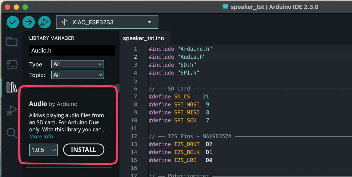
  #include "Arduino.h"
#include "Audio.h"
#include "SD.h"
#include "SPI.h"

// ── SD Card (matches Seeed Studio XIAO ESP32-S3 Sense example) ──
#define SD_CS    21
#define SPI_MOSI 9
#define SPI_MISO 8
#define SPI_SCK  7

// ── I2S Pins → MAX98357A ──
#define I2S_DOUT  D7   // DIN on MAX98357A
#define I2S_BCLK  D6   // BCLK
#define I2S_LRC   D1    // LRC (WS)
#define AMP_SD    D0

Audio audio;

void setup() {
  Serial.begin(115200);

  // Init SPI for SD card (same as Seeed example)
  SPI.begin(SPI_SCK, SPI_MISO, SPI_MOSI, SD_CS);
  if (!SD.begin(SD_CS)) {
    Serial.println("SD Card mount failed!");
    return;
  }
  Serial.println("SD Card mounted.");

    // Keep amplifier enabled
  pinMode(AMP_SD, OUTPUT);
  digitalWrite(AMP_SD, HIGH);

  // Setup I2S output to MAX98357A
  audio.setPinout(I2S_BCLK, I2S_LRC, I2S_DOUT);
  audio.setVolume(21); // 0–21

  // Play the file already on your SD card
  audio.connecttoFS(SD, "/001.mp3");
  Serial.println("Playing 001.mp3...");
}

void loop() {
  audio.loop();
}

// Optional debug callbacks
void audio_info(const char *info)    { Serial.println(info); }
void audio_eof_mp3(const char *info) { Serial.println("Finished playing."); }
code for the speaker.
Motor
I ran into a hardware problem with the motor driver. I had soldered the L9110 in the wrong
orientation pin 1 was where the last pin should have been, so the whole chip was
flipped. 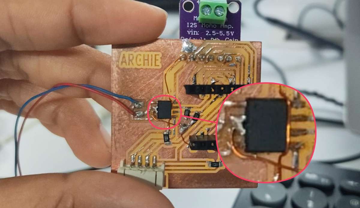 With the pins reversed, power and the inputs went to the wrong places and the driver got hot
very quickly, which is the classic sign of a mis-wired or shorted driver.
I removed the mis-oriented chip, and since it had overheated I replaced it
with a new L9110 and re-soldered it in the correct orientation, double-checking
pin 1
against the datasheet markings before powering up again. After that it ran cool and worked normally.
With the pins reversed, power and the inputs went to the wrong places and the driver got hot
very quickly, which is the classic sign of a mis-wired or shorted driver.
I removed the mis-oriented chip, and since it had overheated I replaced it
with a new L9110 and re-soldered it in the correct orientation, double-checking
pin 1
against the datasheet markings before powering up again. After that it ran cool and worked normally.
To program the motor to spin I drove the L9110's IA and IB inputs from the XIAO. Driving one input high and the other low spins it one way, swapping them reverses it. The code is below.
//code for rotating the motor
#define motorA D2
#define motorB D3

void setup() {
  Serial.begin(115200);
  Serial.println("Code is running");
  pinMode(motorA, OUTPUT);
  pinMode(motorB, OUTPUT);

  // FORCE motor forward immediately
  digitalWrite(motorA, HIGH);
  digitalWrite(motorB, LOW);
  delay(5000);
  digitalWrite(motorB, HIGH);
  digitalWrite(motorA, LOW); delay(5000);
}

void loop() {
}
code for motor.
Spinning the motor slowly:
Since the L9110 has no dedicated PWM
pin, I used
PWM on the IA/IB inputs same as the previous one, to vary the average voltage to the motor. By lowering the duty
cycle the
motor spun slowly, and raising it sped the motor up so I was able to control the speed, which
is what I
need for the DJ-scrub behaviour.
code for controlling the speed of the motor through PWM pins.
#define motorA D2
#define motorB D3

void setup() {
  Serial.begin(115200);
  pinMode(motorA, OUTPUT);
  pinMode(motorB, OUTPUT);
}

void loop() {
  // Forward (slow)
  analogWrite(motorA, 20);  // speed
  digitalWrite(motorB, LOW);
  delay(5000);

  // Reverse (slow)
  digitalWrite(motorA, LOW);
  analogWrite(motorB, 20);
  delay(5000);

  // Stop
  digitalWrite(motorA, LOW);
  digitalWrite(motorB, LOW);
  delay(3000);
}
Conclusion
This week pushed me well beyond just "blink an LED" output,I was trying to read music off an SD card and control playback from the motion of a disk, DJ style. Getting there took a lot of trial and error.
The MAX98357A and I2S took some reading to wrap my head around, but once I understood it the wiring made sense. The SD card was the part that frustrated me most, my code was fine the whole time and it was a loose connection holding me back, which was a good reminder to always suspect the hardware too, not just the software.
The motor side taught me the most the hard way. Soldering the L9110 in the wrong orientation and watching it heat up made the importance of checking pin 1 against the datasheet very real.
By the end I had a board that could play audio and drive a motor with adjustable speed, the core pieces my final project. There's still alot of tuning to do but this week got the foundation working.
Final Files
PCB FilesArduino Files