Week 14 – Molding and Casting
This week is about molding and casting process, we made hard mold from machine wax then made soft mold from silicon and finally hard object using resin..
The objective is to learn workflow of : Design → Mold → Cast → Replicate, this process give us power to not just make one object but make multiple objects.
AI prompt ChatGPT: " can you give me an image by referring this text - I worked on Molding and Casting, creating a BMW M3 GTR logo.My motivation was to build a piece that constantly reminds me of my goal to own the NFS BMW M3 GTR.I designed the mold in Fusion 360, machined it using the TRAK DPM RX2, and completed the process with silicone molding and resin casting. "
Assignment Overview
- Review the safety data sheets for each of your molding and casting materials, then make and compare test casts with each of them
- Compare mold making processes
- Design a mold around the process you'll be using, produce it with a smooth surface finish that does not show the production process toolpath, and use it to cast parts
- Extra credit: use more then two mold parts
| Day | Activity | Status |
|---|---|---|
| Thursday | Class - Molding & Casting, Group Assignment | Completed |
| Friday | Started 3D Design 📐 | completed |
| Saturday | Final Project - Gantt Chart | Completed |
| Smart-UPDI PCB Soldering 🛠 and Documentation 📝 | Completed | |
| Sunday | Worked on FInal project Neopixels Ring and Documentation 📝 | Completed |
| Started 3D design 📐 | Completed | |
| Monday | Designed and CAM the final object Mold in Fusion 📐 | Completed |
| Tuesday | Regional Review 👨🏫💬 | Completed |
| Milling the Mold 🛠 | Completed | |
| Wednesday | Casting The final object 🛠 | Completed |
| Documentation 📝 | In progress |
Group Assignment
We learned about the mixing ratios for e to make soft mold and mixing ratio of resin to cast the final object.
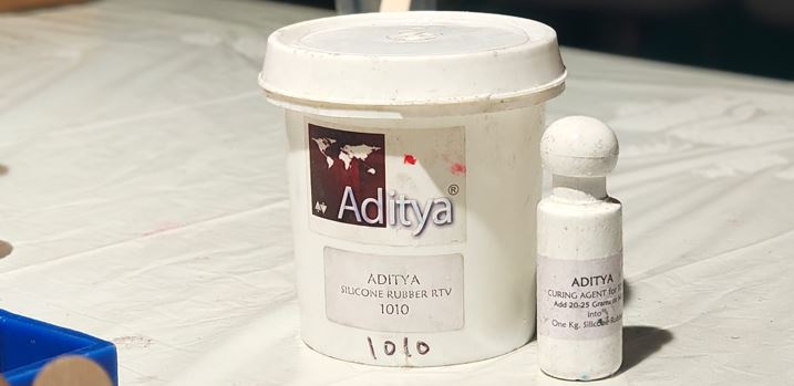
My Learning from group assignment : We used Aditya Silicone Ribber RTV 1010 with harder/curing agent Aditya curing agent to make mixture for soft silicone mold. Every 1 kg of liquid silicone, we need 20-25 grams of hardener. The settling time of the mixture is 8 to 10 minutes, the viscosity changes after that it starts becoming harder so we need to pore into he hard mode with in 8-10 minutes. Avoid air bubbles while mixing, remove bubbles using vacuum pump then pour the mixture into the mold, always pore with tiny string in the small gaps first, tap the mold for even distribution/settlement. The soft mold curing time is 12-24hrs.
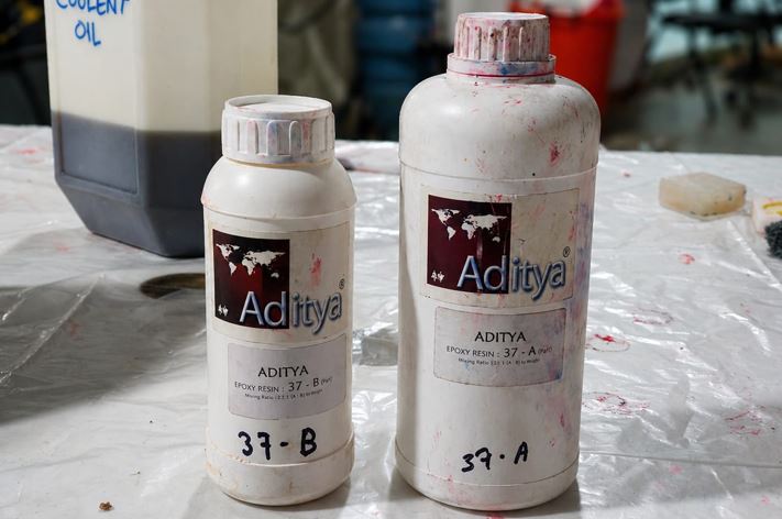
My Learning from group assignment : We used Aditya Epoxy resin part A and part B in the 2:1 ratio to make mixture for final hard Object. Every 2 part of A shall be mixed with 1 part of B. We pour the water into the mold to measure the amount of resin, we measure resin by mass and then calculate the ratio. For example, Resin ratio 2A: 1B, 40.5g part A, 20.25g part B. Do not vacuum the mixture because it makes the transparent clean mixture yellowish. Use mold releasing spray 1083 on the mold before pouring the resin. Setting time for resin is less than silicone, It takes around 18 hours to completely cured, You can speed up the process by adding UV.
As a part of group assignment, I tried poring resin into one of already available silicone mold, as I wanted to see how transparent clean object will look like thus I did not add any alcohol based color to it and kept it transparent. later I wanted to try embedding LEDs into transparent resin.
Design (According to Constrains and Lab Machine capability)
First thing first - Constrains: The job piece size we were allocated to is 76mm X 76mm X 38 mm, so I need to make my design with in this boundary. The minimum tool size that our lab has is Flat End Bit 3.175 mm for milling and Ball End Bit 3.175 for finishing curve surfaces after Flat End Bit milling. We also have 6mm FLat End Bit. The Tool Depth varied between 25mm to 32mm (this is also subjected to bit incursion in the tool holder) . As we have 3 axis machine, the tool shall have straight access to for milling the machine cannot insert the tool at any angel with z axis. The outer walls shall have 1° - 2° Tapper Angle so that the silicone mold can come out easily. The side wall and bottom thickness of minimum 5mm should be left. Last but important, to provide registration in case of two part dies.
Model design
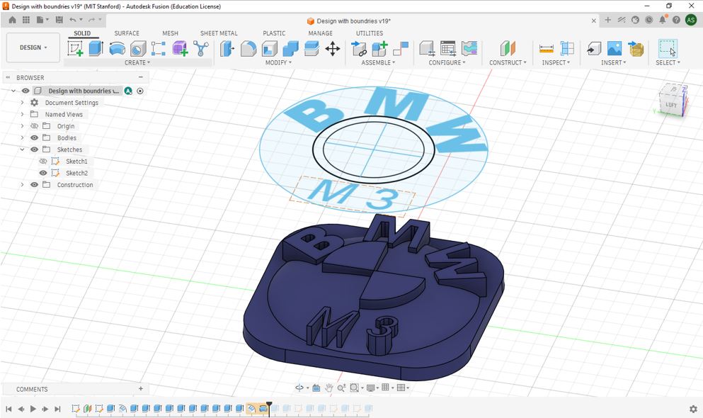
First, I made an sketch for size of my logo on the XY plane and then drew a off-set plain above it and used Text on path function to write BMW on a circle then used normal Text function write M3. Then extruded the Badge and use Emboss function to emboss BMW and M3 on the Badge. The I embossed the second and forth quadrants of central circle and then used Revolve function to make circular cure to have BMW logo like feel.
Mold design
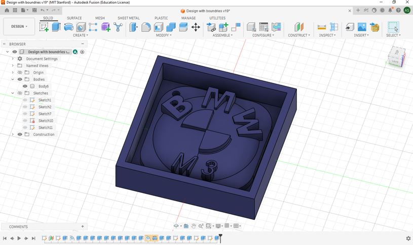
As our workpiece size is 76mm X 76mm X 38 mm, so I drew a rectangle using Centre Rectangle function. I need to keep 5mm wall thickness on all 4 side thus I drew another rectangle on same center of 66mm X 66mm to get 5mm wall thickness on all sides.
CAM - Fusion 360
Now, now we need to change the workspace from Design to Manufacturing. Basically, verifying or validating our Computer Aided Design by Computer Aided Manufacturing to ensure the design can be manufactured in the actual machine with tha given machine and tool constrains.
End mills
We used Academy_Fusion360_Tool_Library, which was made and shared by our instructor Revisankar S. I am going to use two end mills to mill my mold and one ball mill to have finished surface.
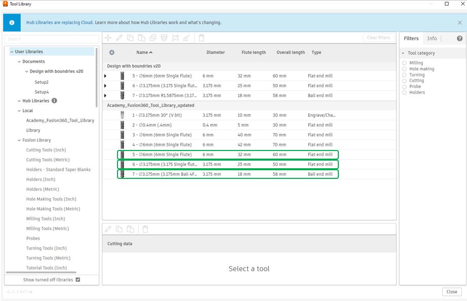
Step 1, thing is to import Tool Library, click Manage --> Tool Library --> Local --> Right click --> Import Library --> Select library path --> OK --> Close.
[Note : you may not see "M3" at teh bottom of the logo because I add the "M3" test after screen recording below videos.]
Step 2, click on NC Program --> Post --> choose from library --> search --> TRAK --> Select --> ProtoTRAK GCD --> copy to my --> ok.
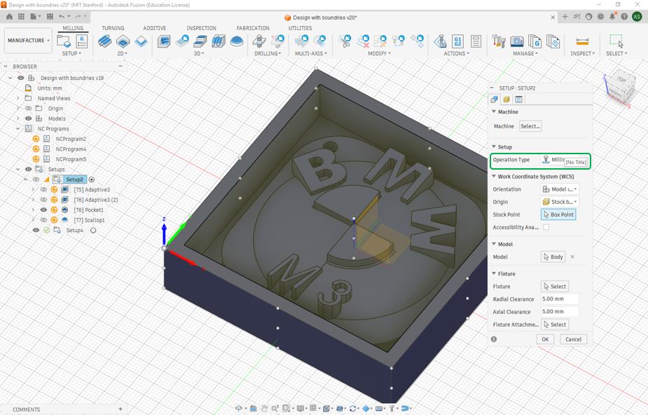
Step 3, setup origin Setup --> New Setup --> Stock point --> select the point --> Stock tab --> Stock side offset : 0 --> Stock Top offset : 0 --> OK.
Step 4, right click setup --> edit --> setup tab --> operation type --> Milling.
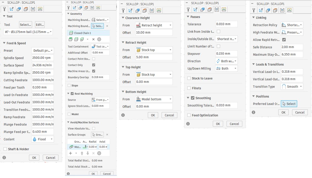
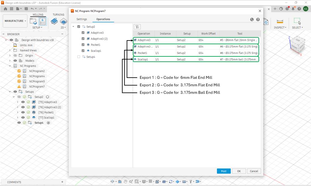
In total, I had four operations - 1 Adaptive cleaning operations with 6mm flat end bit, 1 Adaptive cleaning operations with 3.175mm flat end bit, 1 Pocket operation with 3.175mm flat end bit and 1 Scallop operation with 3.175mm ball end bit - to CAM mu Mold.
Operation 1 Adaptive Cleaning [Rough Cut with 6mm flat end mill]
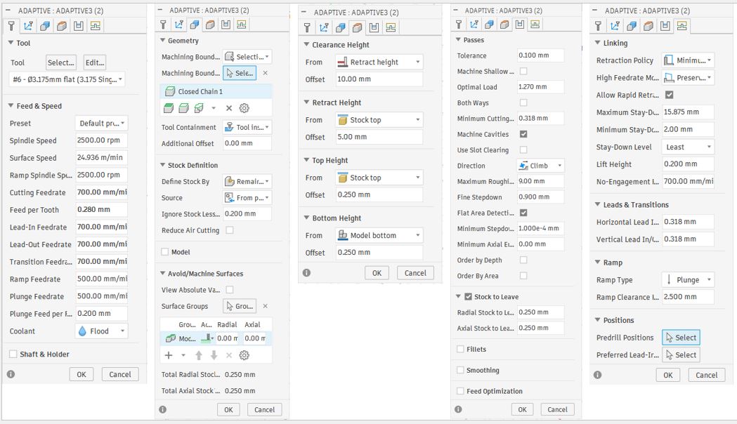
Step 5, setting up adaptive cleaning function for 6 mm flat End bit.
- Part A, 3D --> Adaptive cleaning --> Tool Tab --> Select --> Local --> Academy_Fusion360_Tool_Library_updated --> 6mm bit with 32 length --> select --> spindle speed : 2500 --> Cutting federate : 900 .
- Part B, Geometry Tab --> Machining boundary : Selection --> Machine boundary selection --> inside wall edge --> Tool Containment --> Tool inside boundary .
- Part C, Heights Tab --> Bottom Hight --> Offset --> 0 mm .
- Part D, Passes Tab --> Maximum rough : 9mm --> radial stock to leave : 0.25.
- Part E, Linking Tab --> Ramp Type --> Plunge --> Retraction Policy : Minimum Retraction --> ok .

Step 6, check simulation, right click --> [T5]Adaptive --> simulate --> stock --> uncheck "toolpath" --> click play.
Operation 2 Adaptive Cleaning [Rough Cut with 3.175mm flat end mill]
Now, I repeated step 5 and step 6 but with below settings.
- Part A, 3D --> Adaptive cleaning --> Tool Tab --> Select --> Local --> Academy_Fusion360_Tool_Library_updated --> 3.175mm Flat bit with 32 length --> select --> spindle speed : 2500 --> Cutting federate : 700 .
- Part B, Geometry Tab --> Machining boundary : Selection --> Machine boundary selection --> inside wall edge --> Tool Containment --> Tool inside boundary .
- Part C, Heights Tab --> Bottom Hight --> Offset --> 0.250 mm .
- Part D, Passes Tab --> Maximum rough : 9mm --> radial stock to leave : 0.25.
- Part E, Linking Tab --> Ramp Type --> Plunge --> Retraction Policy : Minimum Retraction --> ok .
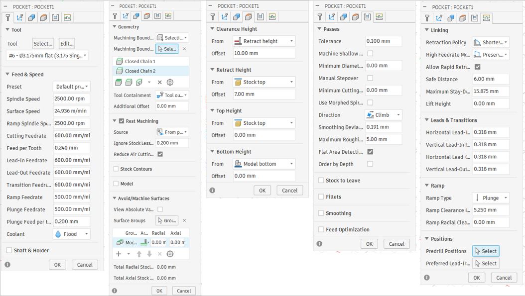
Operation 3 Pocket Cleaning [Rough Cut with 3.175mm flat end mill]
Again, I repeated step 5 and step 6 but with below settings.
- Part A, 3D --> Pocket cleaning --> Tool Tab --> Select --> Local --> Academy_Fusion360_Tool_Library_updated --> 3.175mm Flat bit with 32 length --> select --> spindle speed : 2500 --> Cutting federate : 600 .
- Part B, Geometry Tab --> Machining boundary : Selection --> Machine boundary selection --> Select the square-edge of the logo--> Tool Containment --> Tool outside boundary .
- Part C, Heights Tab --> Bottom Hight --> Offset --> 0.250 mm .
- Part D, Passes Tab --> Maximum rough : 5mm --> uncheck stock to leave .
- Part E, Linking Tab --> Ramp Type --> Plunge --> Retraction Policy : Shortest Retraction --> ok .
Operation 4 Scallop Cleaning [Rough Cut with 3.175mm ball end mill]
Again, I repeated step 5 and step 6 but with below settings.
- Part A, 3D --> Scallop --> Tool Tab --> Select --> Local --> Academy_Fusion360_Tool_Library_updated --> 3.175mm ball bit with 32 length --> select --> spindle speed : 2500 --> Cutting federate : 1000 .
- Part B, Geometry Tab --> Machining boundary : Selection --> Machine boundary selection --> Select the well-edge of mold--> Tool Containment --> Tool center on boundary .
- Part C, Heights Tab --> Bottom Hight --> Offset --> 0 mm .
- Part D, Passes Tab --> Stepover --> 0.150mm--> uncheck stock to leave .
- Part E, Linking Tab --> Retraction Policy : Shortest Retraction --> ok .
Generate G-Code
To generate G code for 6 mm Flat End Mill, click NC Program --> Operations --> checkmark all the operations that I needed with 6mm flat end mill--> Settings --> Post --> ProtoTrak GCD / prototrak --> give File name --> Select Output folder --> Post . Download 6mm Flat End Mill (.gcd File)
To generate G code for 3.175 mm Flat End Mill, click NC Program --> Operations --> checkmark all the operations that I needed with 3.175mm flat end mill--> Settings --> Post --> ProtoTrak GCD / prototrak --> give File name --> Select Output folder --> Post . Download 3.175mm Flat End Mill (.gcd File)
To generate G code for 3.175 mm Ball End Mill, click NC Program --> Operations --> checkmark all the operations that I needed with 3.175mm ball end mill--> Settings --> Post --> ProtoTrak GCD / prototrak --> give File name --> Select Output folder --> Post . Download 3.175mm Ball End Mill (.gcd File)
Machining
Machine Pre-Setup
Prior to machine operation, a pre-start inspection was performed to ensure safe and stable working conditions.
- Verified lubricant level, coolant level, and air pressure supply.
- Confirmed that the machine and work area were clean, organized, and free of any obstructions.
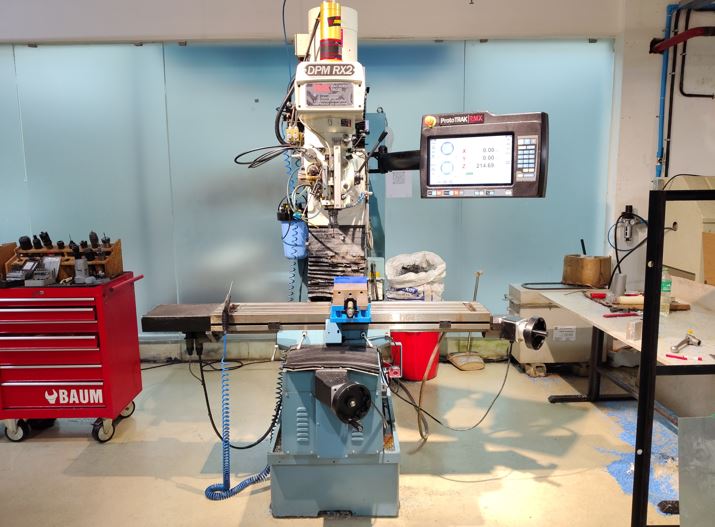
The ProtoTRAK DPM RX2 milling machine was started and initialized to establish machine control and enable axis movement. It is 3 axis vertical milling machine, it doesn't have ATC (automatic tool changer), we need to manually load the tool. It has hand wheels and also servo motors to move the job bed.
- Powered on the machine using the main power switches.
- Allowed the control interface to complete its startup sequence.
- Pressed the RESET button until the status indicator illuminated.
- Confirmed that the servo motors were activated and ready for operation.
Workpiece Setup
The machinable wax stock was carefully fixture in the vice to provide a rigid and accurate setup for machining operations.
- Positioned and clamped the wax block in the vice.
- Checked alignment relative to the machine's X, Y, and Z axes.
- Applied sufficient clamping force to ensure a stable and vibration-free setup.
Tool Setup - Edge Finder (X and Y Origin)
The X and Y datum positions were established using an edge finder to ensure accurate alignment between the machine coordinate system and the CAM-generated toolpath. The machine has Spring loaded edge finder tool, make sure that we rotate it always below 600 rpm. This tool is use to find the x edge and y edge.
- Mounted the edge finder in the spindle.
- Probed the workpiece edges to determine their exact locations.
- Defined the X and Y work offsets based on the measured edge positions.
- Verified that the machine coordinates matched the origin specified in the CAM model.
Z-axis reference position
The Z-axis reference position was initialized to establish a repeatable machine datum and ensure safe tool movement throughout the machining process.
- Navigated to SYSTEM → SETUP → REFERENCE POSITION.
- Configured the reference using Z RETRACT → SET → ABSOLUTE SET.
- Stored the machine's absolute Z retract position as the reference point.
- This machine-level reference minimizes the risk of collisions and provides a consistent starting position for machining operations.
DRO (Digital Readout) Setup
The Digital Readout (DRO) was configured to define the work coordinate system and establish the machining datum. DRO for movement manually and automatic
- Assigned the X and Y work offsets using the ABSOLUTE SET function.
- Referenced the Z-axis from a fixed base surface rather than the top of the stock material.
- This method preserves a stable and repeatable Z reference throughout the machining operation.
- Maintains coordinate consistency even after successive material removal passes.
- Return 0 - work origin point
- Line center - to find object center
Program Loading
The CAM-generated G-code program was imported into the machine controller and configured for machining.
- Loaded the machining program using the PROGRAM IN/OUT function.
- Reviewed the imported toolpath to ensure the correct file was selected.
- Initialized the first machining operation using the 6 mm cutting tool.
- Verified program settings prior to execution.
Tool Table Configuration
The tool table was configured to define the cutting tool geometry and establish the required machining offsets. Tool table - specify tool for operation
- Accessed the machine's TOOL TABLE.
- Specified the tool diameter, tool classification, and Z-axis reference (BASE).
- Used the ABSOLUTE SET function to save the tool offset data.
- This configuration ensures accurate tool positioning and proper interpretation of the CAM-generated toolpath.
Manual Positioning and Reference Check
A manual positioning check was performed to ensure the cutting tool was correctly aligned with the established machining datum and CAM-defined coordinate system.
- Jogged the tool to the designated base reference location.
- JOG mode to move XYZ direction
- Verified the tool position relative to the programmed work offsets.
- Confirmed consistency between the physical setup and the CAM-generated origin.
- Validated the setup prior to commencing machining operations.
Toolpath Verification (TRAK Mode)
A pre-machining validation step was performed to confirm toolpath accuracy and verify the machine setup before executing the program.
- Activated TRAKing mode for controlled manual inspection.
- Moved the tool to the programmed origin location and verified alignment.
- Advanced through the toolpath incrementally using the FORWARD command.
- Checked that the tool movement matched the intended CAM-generated machining sequence.
- After successful verification, exited TRAKing mode and proceeded with machining in CNC RUN mode.
Program Execution
Upon completion of the verification process, the machining program was initiated for automated execution.
- Started the program using the GO command.
- Prog - select the program
- The machine followed the CAM-generated toolpath and machining parameters.
- All cutting operations were performed automatically based on the programmed sequence.
- Machine motion and tool engagement were continuously controlled by the CNC system throughout the operation.
Tool Change and Subsequent Operations
The setup and machining procedure was repeated for each tool and machining operation to ensure accurate execution of the complete manufacturing process.
- Installed the appropriate cutting tool for each operation, such as flat end mills and ball end mills.
- Re-established the work coordinate system and Z-axis reference following every tool change.
- Updated the TOOL TABLE with the correct tool geometry and offset information.
- Validated tool position and alignment prior to running each machining cycle.
- Maintained consistent accuracy and repeatability across all machining operations.
Operation 1 : 6mm Flat End mill
The first operation used a 6 mm single flute flat end mill to remove bulk material and establish the primary cavity shape
Operation 2 & 3 : Adaptive Cleaning and Pocket Cleaning with 3.175 mm Flat End mill
The second operation used a 3 mm single flute flat end mill to remove further material and further refine the the primary cavity shape.
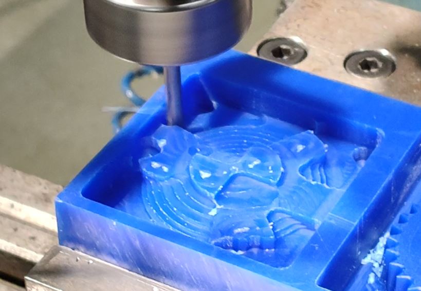
Operation 4 Scallop Cleaning with 3.175mm ball end mill
A 3.175 mm ball end mill was used for finishing, enabling smooth surface transitions and accurate reproduction of curved geometry.
In Summary
- Our lab has a 3-axis vertical milling machine. It does not have an ATC (Automatic Tool Changer), so tools must be loaded manually. The machine is equipped with both handwheels and servo motors for moving the worktable.
- We use Fusion 360 CAM software to generate the G-code required for machining operations.
- The machine uses a spring-loaded edge finder. Ensure that it is always operated below 600 RPM. This tool is used to locate the X-axis and Y-axis edges of the workpiece.
- Check the lubricant level and coolant level before starting the machine, then power it on.
- After startup, activate all servo motors by pressing and holding the RESET button until the indicator light turns on.
- Use the TOOL TABLE to specify and configure the cutting tool for each machining operation.
- The DRO (Digital Readout) is used for both manual and programmed machine movement.
- RETURN 0 is used to move the machine to the defined work origin point.
- LINE CENTER is used to locate the center of a workpiece or feature.
- JOG Mode is used to manually move the machine in the X, Y, and Z directions.
- PROG is used to select and load the machining program.
- The maximum feed rate of the machine is approximately 5000 mm/min.
- Spindle rotation direction depends on the cutting tool being used. Some tools require clockwise rotation, while others require counterclockwise rotation.
- When changing a tool in the chuck, lock the clutch before loosening or tightening it.
- Always keep your fingers below the flat edge of the chuck during tool changes. This is a critical safety precaution.
- The vice is the primary workholding device used to securely clamp the workpiece during machining.
Molding
In the group assignment, I learned about the mixing ratios for silicone to make soft mold, we used Aditya Silicone Ribber RTV 1010 with harder/curing agent Aditya curing agent to make mixture for soft silicone mold.
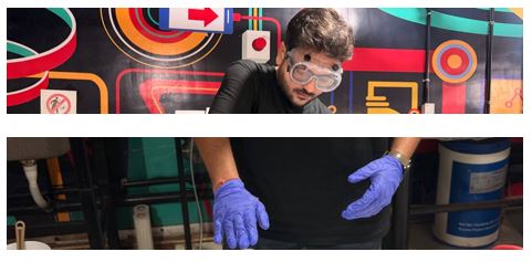
Safety
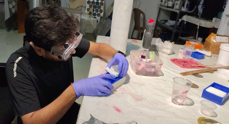
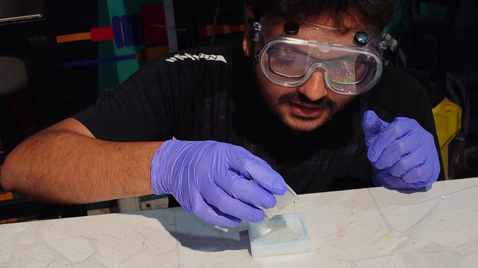
Safety first - I used Nitrile GLoves to protect my hands and safety goggles to protect my eyes while doing Molding with liquid silicone and hardening agents.
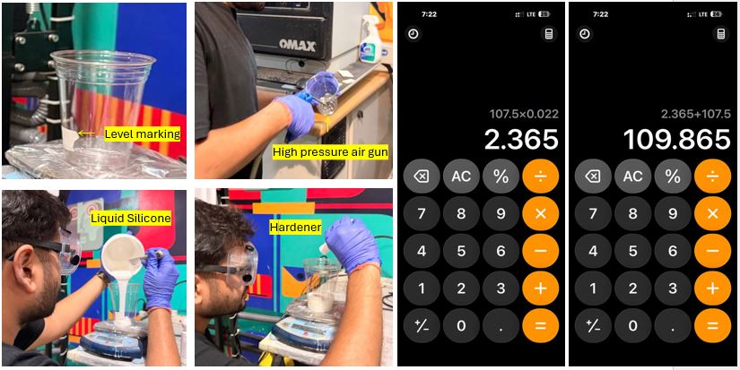
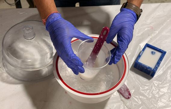
Mixing ratio
Every 1 kg of liquid silicone, we need 20-25 grams of hardener. I used ratio 1000:22. First, I approximate the required silicone my poring water into the hard mold and taking it into transparent glass, then marking the level of the water and cleaned the glass with high air-pressure gun. The total weight of my hard mold's liquid silicone was 107.5 gm, I added 2.365 gm of hardener. Total weight added upto 109.865gm. Note : Mix slowly to avoid air bubbles formation.

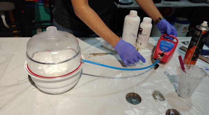
Removing Bubbles
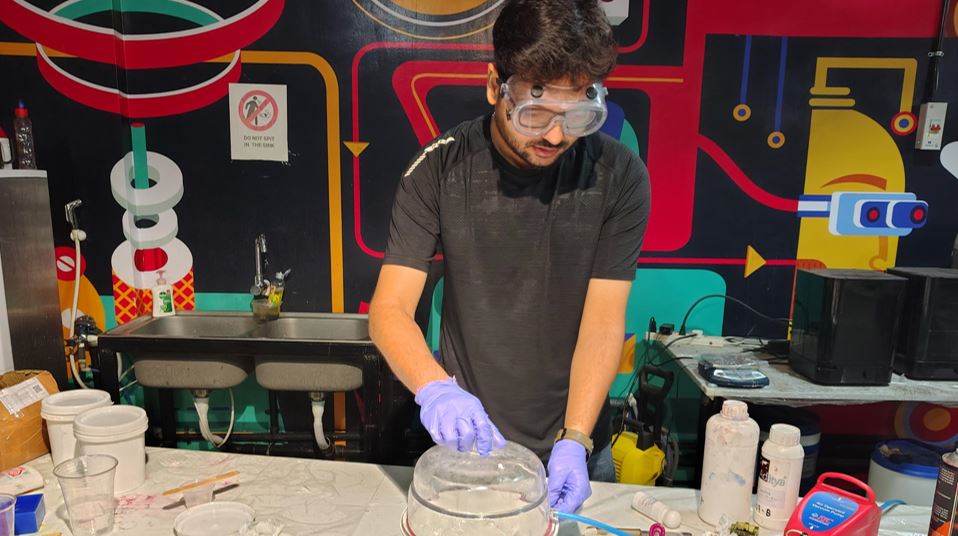
Now, I used vacuum chamber to remove air bubbles from the mixture, the chamber used high-air pressure line to rotate a vacuum pump. I kept the glass with the mixture inside the chamber and waited for air bubbles to come-up. The air bubbles will come-up and then blast and mixture will settle down.
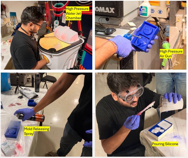
Pouring Silicone
Now, I clean the hard mold with high pressure water jet chamber and then cleaned and dried the Hard Mold using air pressure gun. Then applied the mold releasing spray on the hard mold and then poured the silicone mixture into the hard mold. Here, while pouring it is important that we pour first in tiny/small gaps of the hard mold with thin pouring of silicone. Tap the mould for even distribution/settlement, if required then vacuum it again to remove bubbles. And then I kept it for settling for 17-20 hours.
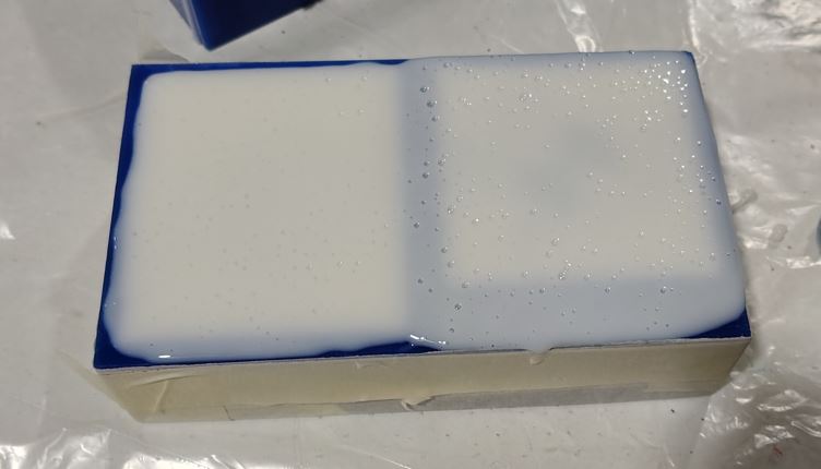
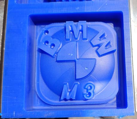
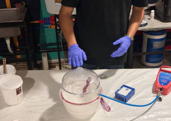
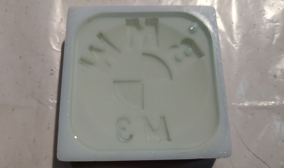
After Settling
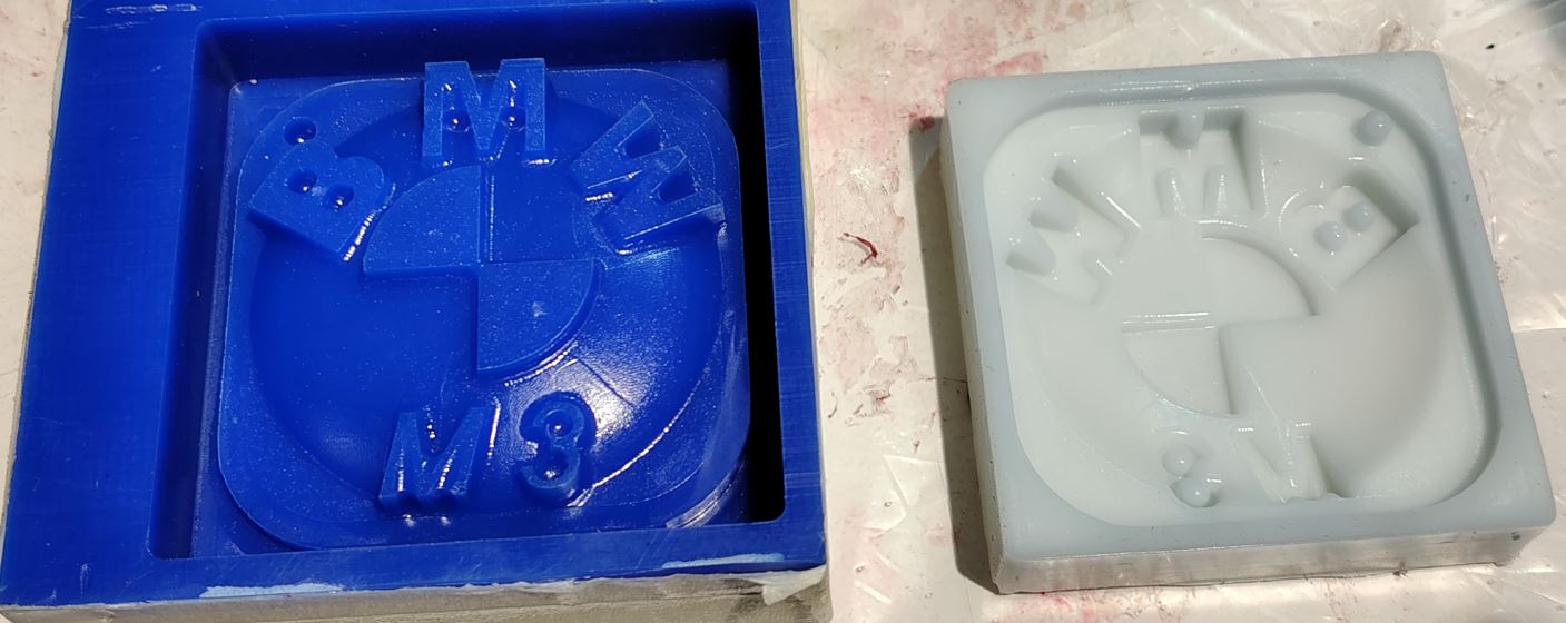
After about 17 hours, I removed the silicon soft mold from hard mold. I came out well and without any bubbles!
Casting
Safety
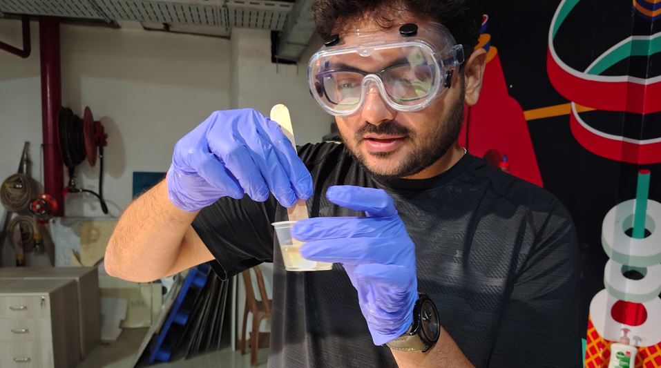
Safety first - I used Nitrile GLoves to protect my hands and safety goggles to protect my eyes while doing Molding with liquid silicone and hardening agents.
Mixing ratio
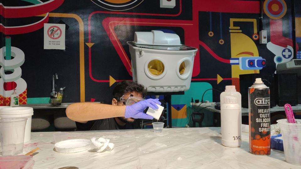
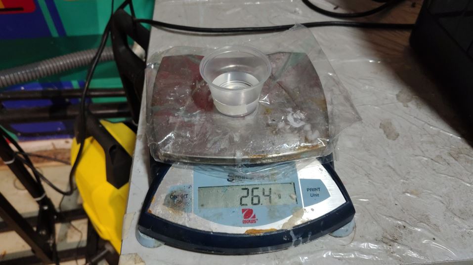
Every 2 part of A, we need 1 Part of B. I used ratio 2A:B. First, I approximate the required mixture quantity by poring water into the silicon mold and taking it into transparent glass, then marking the level of the water and cleaned the glass with high air-pressure gun. The total weight of my soft mold's resin was 26.4 gm, I added 17.6 gm of part A and 8.8 gm of part B. Total weight added upto 26.4gm. Note : we may add little extra of part A and part B in 2A:B ration so that we have enough resin to pour in the silicon mold and importantly make sure to clean the soft mold using high pressure aur after removing the water from it. We may vacuum it if require to remove air bubbles.
Pigment/Color
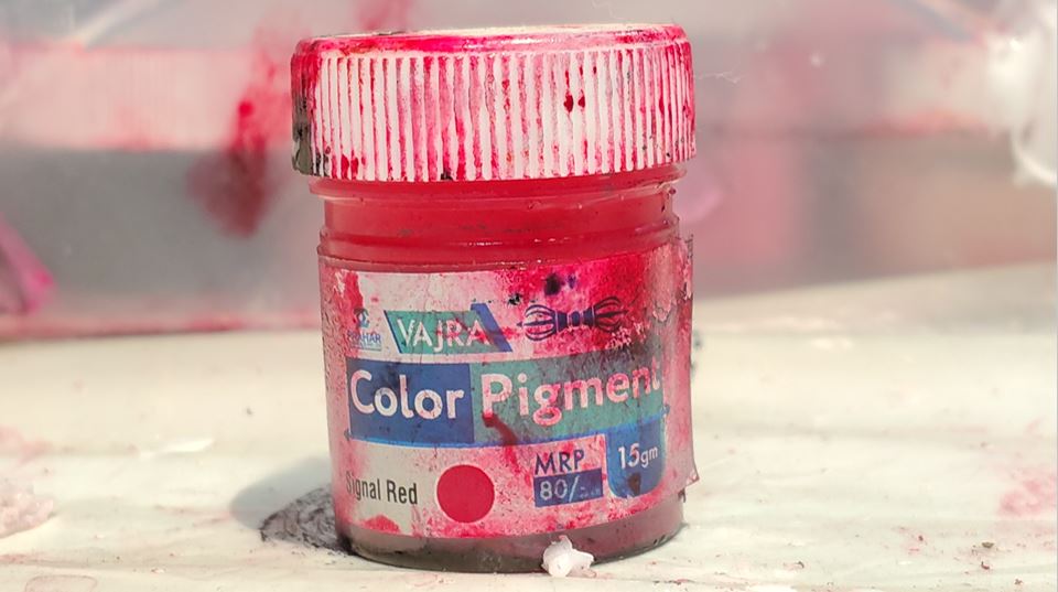
I did not added any color however if we need color object then we can add Alcohol based color, add a tint of color (very minimal amount).
Pouring Resin and Settling
Now, I clean the silicon mold with high pressure water jet chamber and then cleaned and dried the silicon Mold using air pressure gun. Then applied the mold releasing spray on the silicon mold and then poured the resin mixture into the silicon mold. Here, while pouring it is important that we pour first in tiny/small gaps of the mold. And then I kept it for settling for 18 hours.
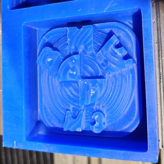
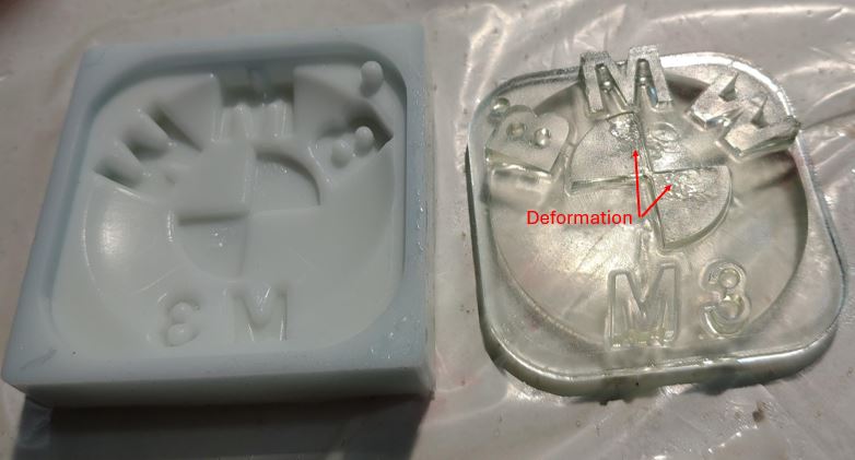
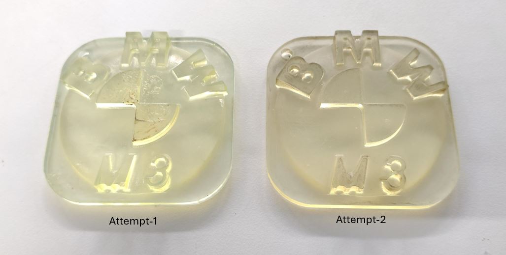
Mold Release
After about 17 hours, I removed the resin from soft mold. In first attempt it had some deformation on the flat surface thus I tried to pour silicon one more time this time the object came out well and without any bubbles!
Downloads and Useful links
Hard Mold 3D design file is here
G-Code for milling can be download from here
Thej Thomas reference assignment
Neil share this link for 3D printed casting