Molding & Casting
Group Assignment
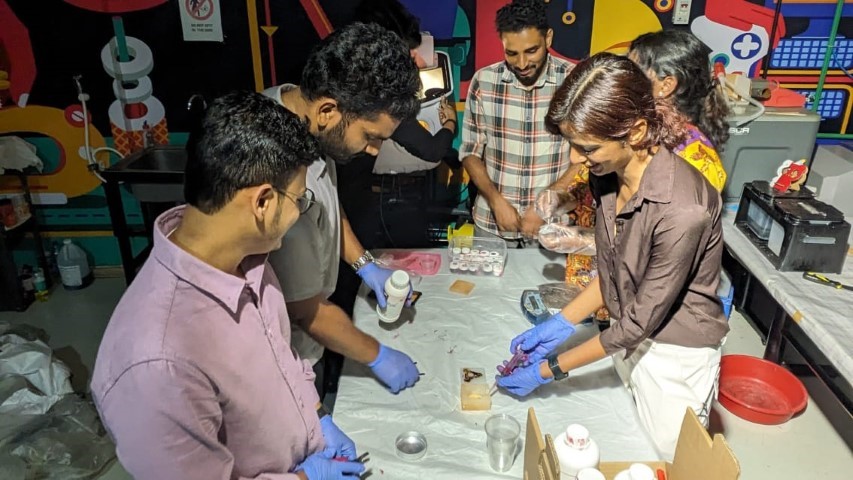
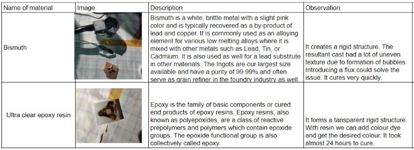
Review the safety data sheets for each of your molding and casting materials, then make and compare test casts with each of them
Compare printing vs machining molds
Individual Assignment
Design a mold around the process you'll be using, produce it with a smooth surface finish, and use it to cast parts
Extra credit: Use more than two mold parts
Group Assignment
Pokeball
This week I was thinking of making a fridge magnet and so I referred some easy designs to do and thought of doing a pokeball.
Molding
First step is to make the mold of the pokeball so that I can cast it.
CAD
I am doing the design in Fusion 360. Here's the design:
.png)
This is how the milled output should be
.png)
After pouring Silicon to that, I should get this mould
.png)
To pour the colours seperately, I'll be keeping this 3D printed part inside the mold.
.png)
.png)
This is the expected output. Some space is left to keep the magnet inside.
.png)
CAM
Milling in Fusion 360 employs a cutting tool to shape workpieces. Users define toolpaths in the CAM workspace, specifying tools, materials, and machining parameters. Simulations ensure accuracy before exporting G-code, instructing CNC machines. This process, integral for complex shapes, extends to various materials like metals and plastics. For instance, a pendant mold design can be crafted in Fusion 360, with CAM defining toolpaths to mill machinable wax. The resulting G-code directs the milling machine, translating digital designs into physical molds, crucial for subsequent silicone casting.
.png)
To access the Manufacturing workspace in Fusion 360, navigate to the Machining section of the dropdown menu and choose Manufacturing Environment.
Once there, the initial step is to configure the machining interface.
This can be done by selecting Setup > New Setup.
Here, you'll define parameters such as the X, Y, and Z axes for your design.
Following the setup, the next crucial step is to define the tools necessary for the job.
This can be accomplished by accessing Manage > Tool Library.
From the local library, you can add the specific tools required for your project.
Alternatively, you have the option to import your entire inventory.
In my scenario, I opted to add the library of my Fab Lab> Fab Tools
.png)
To remove the most amount of material, I used the 6mm flat end bit under 3D Adaptive clearing.
.png)
Next, I used 3mm flat end bit and used it under three configurations to remove the material, same as 3D adaptive layer used above.
.png)
Next was the pencil to get corners
.png)
Next I used flat to get the button shape accurately
.png)
Next was the 3mm ball end bit to get the curved surface with more finish.
.png)
Milling
DPM RX 2- Vertical Milling Machine
The vertical milling machine is a precise tool utilized for shaping and fabricating by removing material, often from metallic workpieces. This process creates flat surfaces or specific features on a workpiece, usually with precise alignment to other components or surfaces.
Key Specifications:
Table Size: 1240 x 230 mm
Motor Type: 3 HP Continuous Spindle Motor
Axis Travel: 800 x 400 x 650 mm
Spindle Taper: R8
Head Swivel: +/- 90 degrees
Quill Diameter: 33/8 inch
Maximum Quill Travel: 5 inch

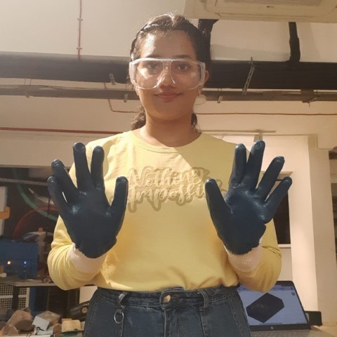
Saftey first! I wore safety glasses and gloves.
I did CAM with three different milling bits: 6mm flat-end bit
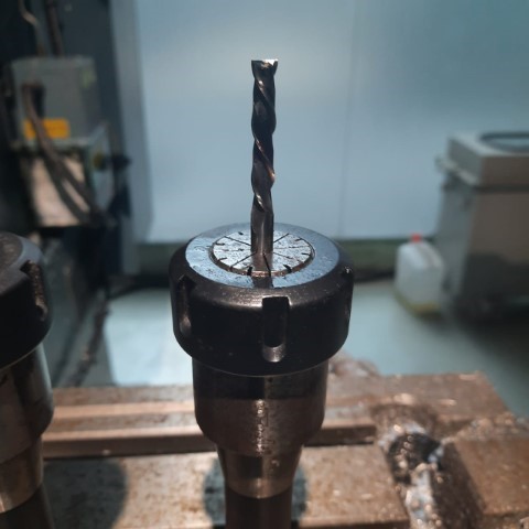
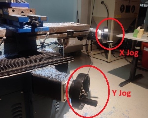
Setting up the machine
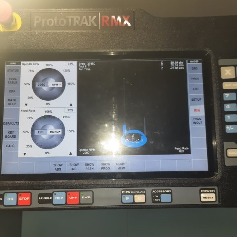
This is the interface, ProtoTRAK RMX CNC - Touchscreen
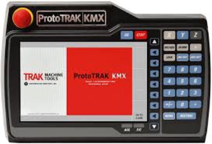
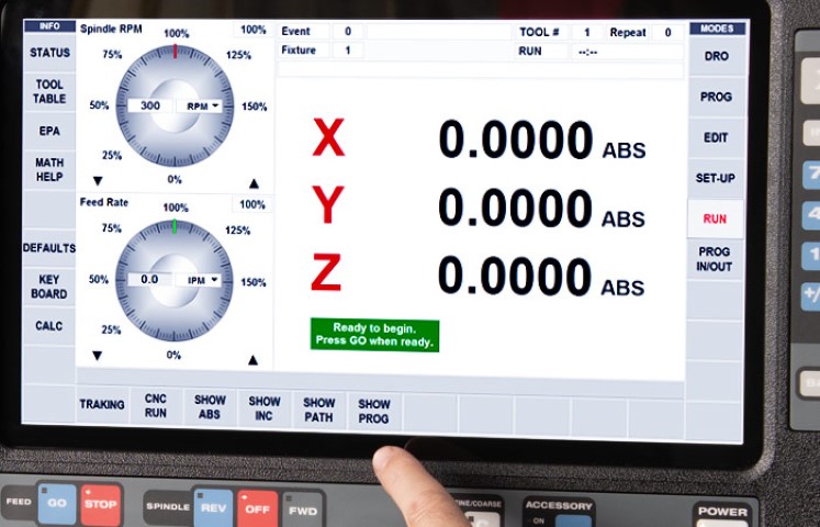
To set up the machine, first switch it on and place the workpiece on the machine vise. After fixing the material, we need to set the origin of the machine. This can be done by adding the tool offset of the machine after fixing the edge finder on the machine.
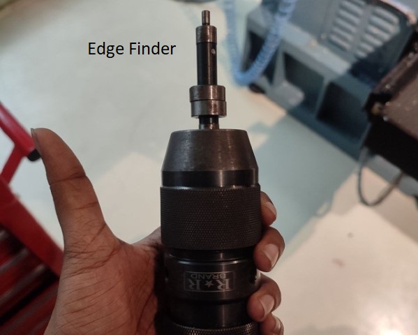
Using Edge Finder
Insert the edge finder probe. Make sure to move to DRO tab and edge finder is on the lest hand side of the wax. Turn on the spindle. Press the “F” (fine) button and move along the x axis using the handwheel. Check the edge finder probe, and as we move the tool towards the wax, the probe will start to align properly. Stop rotating the wheel once the probe is misaligned. Then press “ABS SET” from the keypad. The diameter of the probe is 4 mm, so add 2mm to the x value. Press again “ABS SET” from the keypad to set the X to zero. To set the Y-axis, follow the same procedure for X. Rotate the Y axis handwheel in fine mode and stop as soon as the probe is misaligned. Then press “ABS SET”. Add 2 mm to Y and again press “ABS SET”. Now both the X and Y set. When we press the “RETURN ABS 0”. Then press “GO” button to move the tool to the origin.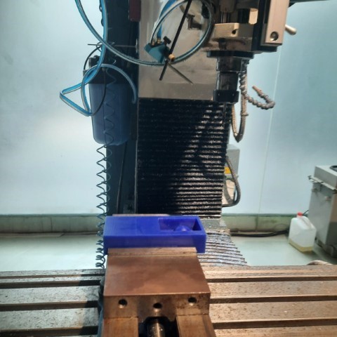
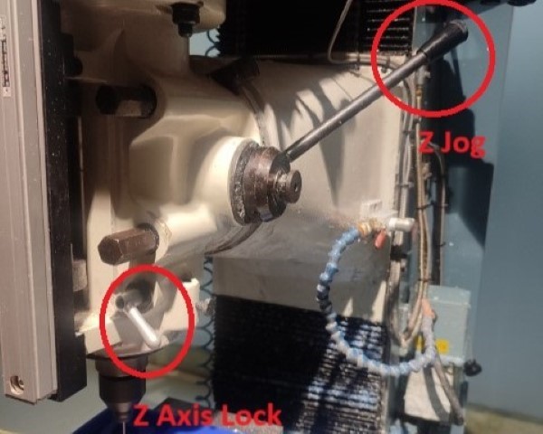
Once the material is secured, adjust the Z and Y axes by rotating the rotary encoders. I added the tool I was using in the tooltable i.e. tooltype, material, flutes, diameter etc. Subsequently, secure the Z axis by lowering the tool. Upon completion of all adjustments, establish the reference Z axis by lowering the tool. T his tool reference is essential to maintain a fixed origin during tool changes.
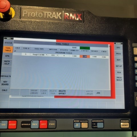
Once the origin is set, next step is to upload the program. Click on "Prog In/Out" on screen and add the file. Next step is to add the tool details such as its diameter, number of flutes etc by clicking on "Tool Table". Once all configurations are finalized, activate the machine using Traking option to track and jog by utilizing the rotary encoders. Once satisfied, click on "CNC Run" for the machine to start milling.to execute the programmed G code and monitor its progress in completing the task. Following the execution of the G code, establish the Z offset and define the tool parameters for the new tool during a tool change, then proceed to operate the machine once more. With the completion of the setup, the process concludes.
I could view the toolpath of the milling bit during the milling process, zoom, pan or rotate the model by using gestures on the touchscreen to see different angles.
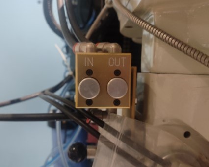
After each milling operation, press on the "Out" button to remove the tool module from the spindle and "In" to add new tool module.
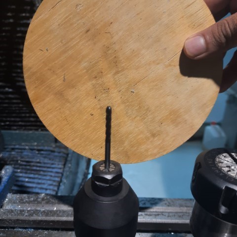
Milling after 6mm flat-end, 3mm flat end and 3mm ball end.
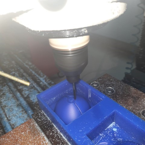
Milling done! Pokemon time!
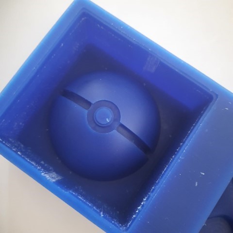
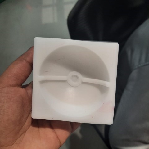
Mold
Next step is to make the silicon mould.
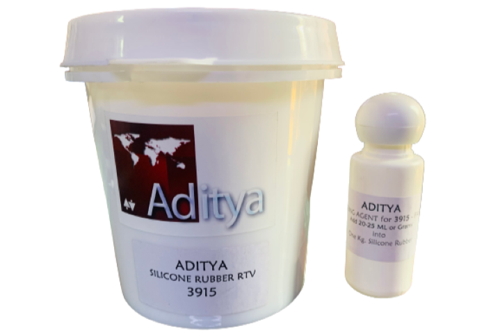
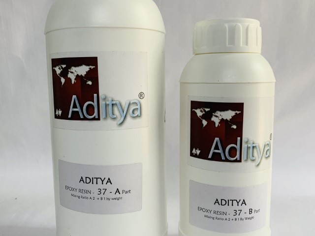
1010 Silicone Rubber RTV (Room Temperature Vulcanizing) is a specialized silicone rubber compound tailored for mold making and prototyping purposes. This two-component compound comprises a silicone rubber base and a curing agent. When combined in the prescribed ratio of 100ml of silicone to 30ml of curing agent, these components trigger the curing process at room temperature. The silicone we used was Adithya Silicone rubber RTV
Here's my mold:
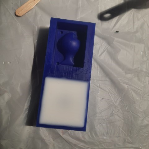
I got my mould done to harden on Saturday night. It takes 24 hours to harden and I was excited to come on Monday and pour resin into it. I brought different colours of glitter to mix in my resin. But I came in morning to see that nothing had hardened. We got the ratio all wrong. It remained the same as I left it on Saturday night.
So here I go again making sure the ratio is right this time.
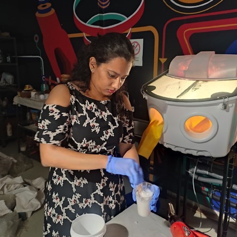
Hopefully this will work out this time. (I don't know why my eyes look like that, Laxmi took the photo)
Success!
Casting
Next step is to pour the resin into the mold.
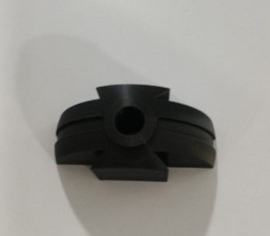
3D printing
So the black part of the pokeball has to be 3D printed as I had mentioned above but in the mold, the corners were rounded because of the milling bit. So I had add fillet into the CAD design before I had it 3D printed.
Resin
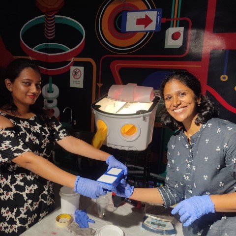
The resin we used was Adithya Ultraclear epoxy and during the group assignment, we had found out the correct ratio to mix the 2 parts of resin. Part B and Part A comes in 2:1 ratio. Therefore for a 15ml volume, I need 7.5ml of Part A and 15ml of Part B. So mix the resin and the colors accordingly and poured it.
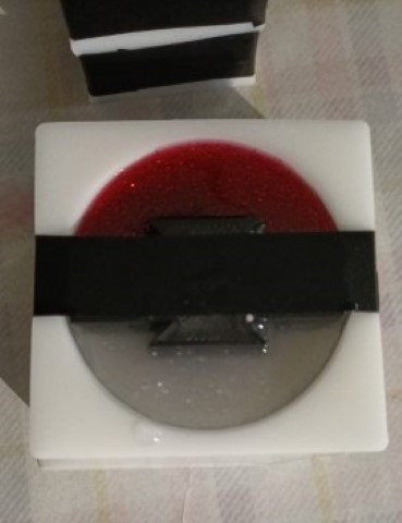
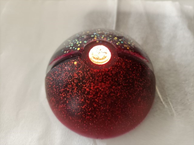
Pokeball
After 16 hours, I took it out of the mold. The white glitter had settled down and the colours had slightly mixed. The button which was supposed to white had mixed with red.