Week 4 — Embedded programming
Group assignment for this week is on the Chaihuo Week 4 group assignment page. The rest of this page is my individual work.
Individual assignment
I picked the Seeed Studio XIAO RP2040, a board I had not used before, and
wrote a small interactive program in the Arduino IDE. The firmware reads a push button, drives
the onboard RGB LED, and accepts on / off over USB serial at
115200 baud.
Learning the XIAO RP2040
Before writing firmware, I read the Seeed Studio XIAO RP2040 wiki and skimmed the RP2040 datasheet for practical bring-up details. The board is built around a dual-core ARM Cortex-M0+ running up to 133 MHz, with 264 KB SRAM and 2 MB onboard flash. For this week, the most useful facts were pin naming, the active-low RGB LED behavior, and the USB-C upload workflow in Arduino.
- Size and I/O: 14 castellated pads, 11 digital pins, 4 analog pins, plus I2C, UART, and SPI.
- Onboard indicators: power LED, user LED, and a 3-color RGB LED controlled by dedicated pins.
- LED polarity: on XIAO RP2040 the RGB channels are active-low, so
LOWturns a color on. - Serial path: USB-C provides both power and the serial monitor connection used for command testing.
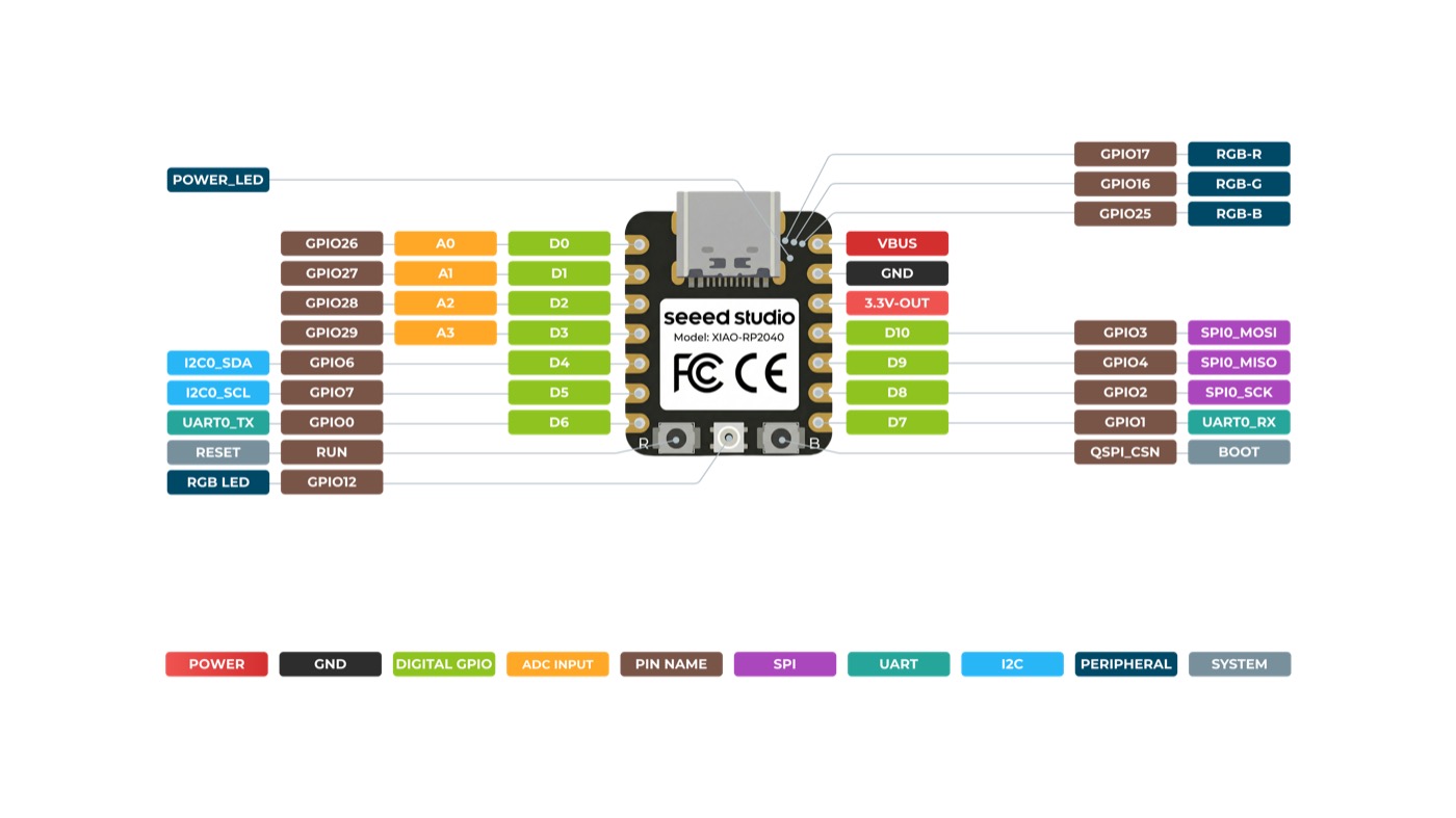
D2 for the button and confirm GND placement.
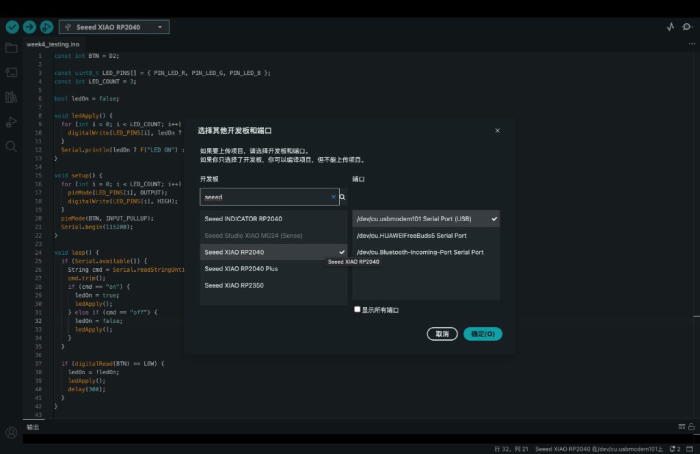
I also installed the Seeed XIAO RP2040 board package in Arduino IDE 2.x, selected the correct USB serial port, and verified that a blank upload could reach the board before adding button and LED logic.
Hardware setup
The test circuit is intentionally minimal: one XIAO RP2040, one breadboard, one tactile button, and two jumper wires. The onboard RGB LED is used as the visible output, so no external LED was required.
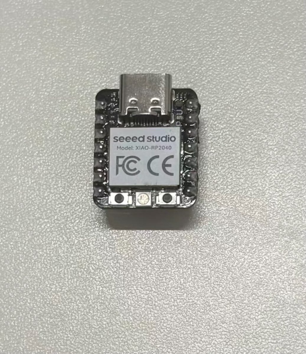
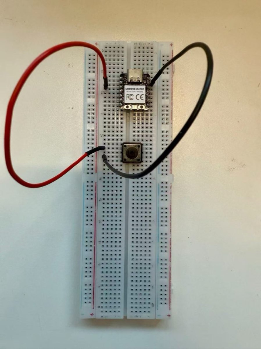
D2 and GND with internal pull-up so a press pulls the pin low.
Program and toolchain
I wrote the firmware in Arduino C++ as sketch week4_testing. The program defines
a shared ledApply() helper that drives all three RGB channels (active-low on XIAO
RP2040), listens for on / off over serial at 115200 baud, and toggles
the LED when the button on D2 is pressed. A 300 ms debounce delay after each button
press prevents multiple triggers from one physical press.
Programming protocol implemented
The protocol for this test is deliberately small, but it is still a real command path: the host sends plain-text USB serial commands and the board answers with a state message. I kept it human-readable so I could debug it directly in the Arduino Serial Monitor before adding any more complicated interface.
| Protocol part | Implementation | What I checked |
|---|---|---|
| Transport | USB Serial at 115200 baud | Board appears as a serial port after upload. |
| Command format | ASCII text commands: on and off |
Newline from Serial Monitor is ignored after trimming. |
| Board response | LED ON or LED OFF |
Serial response matches the visible RGB LED state. |
| Physical input path | Button on D2 with internal pull-up and debounce |
A press toggles the same LED state without using the host command. |
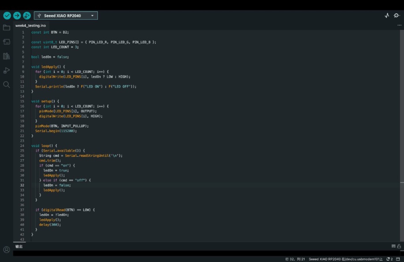
Source code
Download Arduino sketch (week4_testing.ino)
Open in Arduino IDE 2.x with board Seeed XIAO RP2040 and the matching USB serial port selected.
Testing and results
After upload, I opened the Serial Monitor at 115200 baud and verified both control paths.
Sending on turned the RGB LED on and printed LED ON; sending
off did the reverse. Pressing the button toggled the same state without using
the computer keyboard.
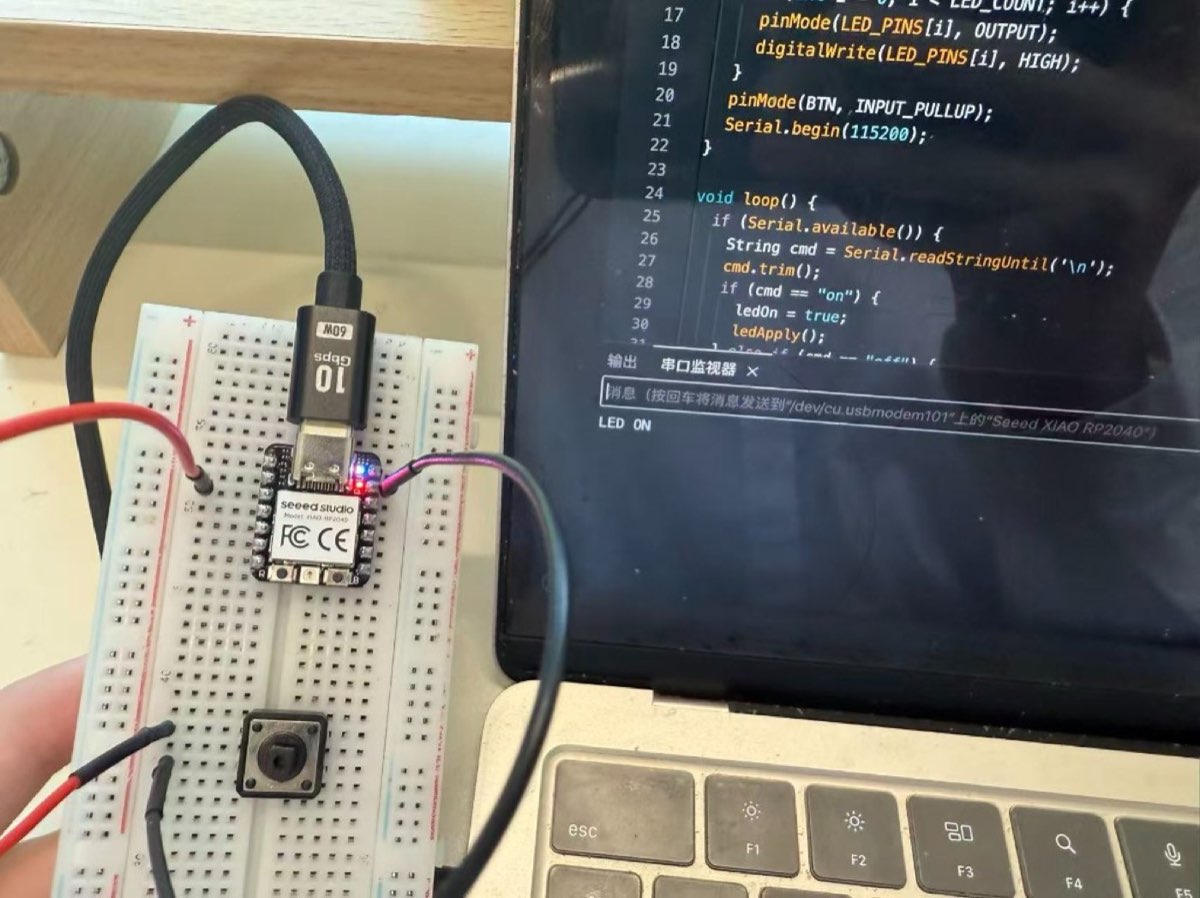
LED ON after sending the on command.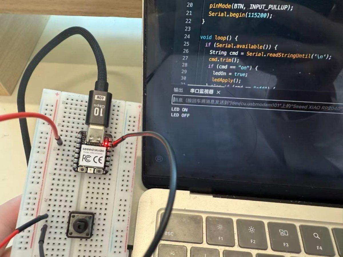
LED OFF after sending the off command.Reflection
The repeatable sequence for me: read the board docs, map pins, wire a simple input, write firmware with one shared output function, then check both serial and physical control paths. Active-low LED behavior and pull-up button wiring mattered most for getting correct results on the first hardware test.
Our group comparison between RP2040 and ESP32-C3 helped before I even picked a board. RP2040’s Arduino path is shorter for a first blink, while ESP32-C3 pays off later when Wi-Fi or more SRAM matters. Knowing where each toolchain fails (wrong board package, missing boot mode, serial port confusion) saved time when classmates hit the same errors on different chips.