Week 3 — Computer-controlled cutting
Group assignment for this week is on the Chaihuo Week 3 group assignment page. The rest of this page is my individual work.
Individual assignment
This week I designed a parametric press-fit construction piece in Onshape, exported a flat DXF, laser-cut several copies from plywood, and assembled them into a small 3D structure. The same triangle outline also went through the lab vinyl cutter as a second CAM path. The design goal was not a one-off shape but a part whose slot width and overall scale can be retuned when material thickness or laser kerf changes.
Design intent
Fab Academy asks for a parametric construction kit that accounts for kerf and can be assembled
in more than one way. I chose an equilateral triangle with three inward slots so identical parts
can interlock at different angles, similar in spirit to a press-fit snowflake or circle kit but
with triangular symmetry. The important design choice is how slot width relates to real board
thickness: our lab stock measured about 3.0 mm plywood, while the slot variable
kerf is set to 2.8 mm so the laser removes slightly less than the
full material width and the joint stays snug after the beam’s kerf loss.
| Variable | Value used | Role |
|---|---|---|
diameter |
40 mm | Inscribed-circle diameter that sets overall triangle scale. |
length |
10 mm (= diameter / 4) |
Slot depth along each edge. |
kerf |
2.8 mm | Slot width; tuned for ~3 mm plywood plus laser kerf compensation. |
chamfer_diameter1 |
1.5 mm → 3 mm | First chamfer offset at slot entry; increased for easier press-fit. |
chamfer_diameter2 |
3 mm → 7 mm | Second chamfer control for the slot mouth opening angle. |
Parametric design in Onshape
I modeled everything in a single sketch driven by variables in the feature tree. The screenshots below follow the order I actually built the part.
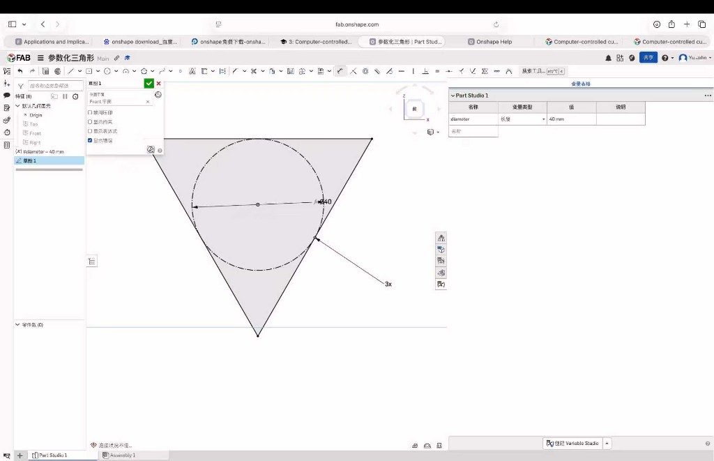
Step 1: Triangle and inscribed circle
I sketched an equilateral triangle with a horizontal constraint on the top edge, then added a
construction circle inscribed inside the triangle. The circle diameter is bound to
diameter (40 mm in this version) so the whole outline scales together when that
variable changes.
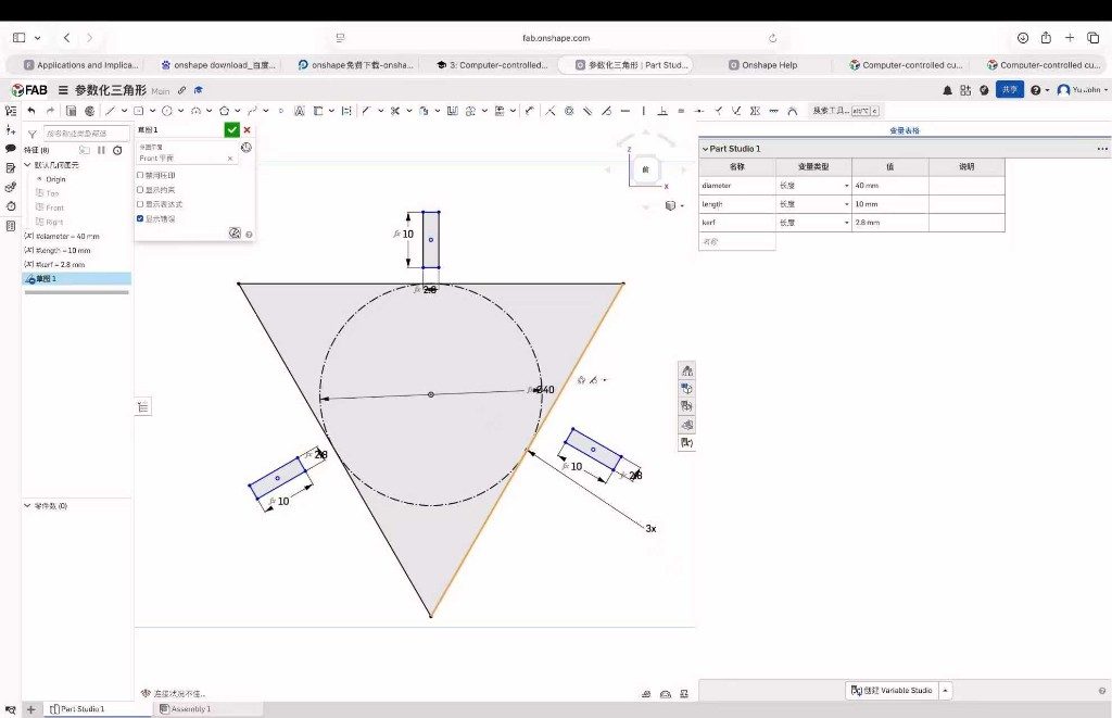
Step 2: Slot rectangles
Three rectangles form the press-fit slots. Width is kerf (2.8 mm) and length is
length (10 mm, one quarter of diameter). Keeping slot depth tied to
overall size means the proportions stay balanced if I resize the kit later.
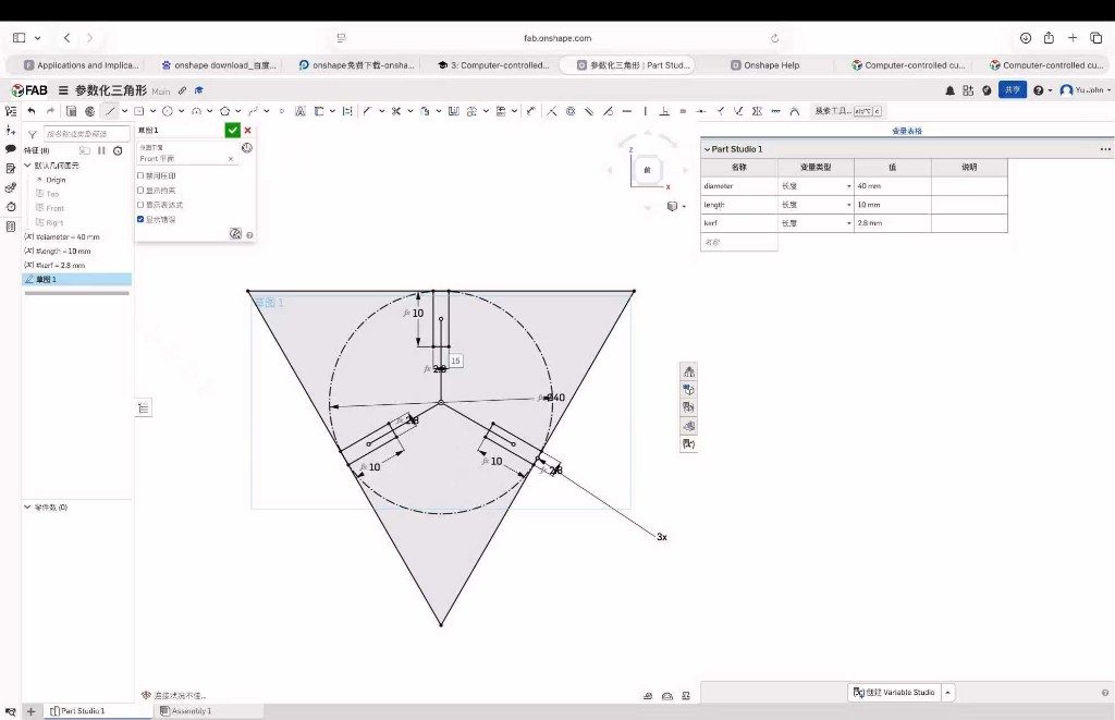
Step 3: Midpoint and coincident constraints
Each rectangle is centered on one triangle edge with midpoint constraints and coincident ties to the outer profile. That keeps the slot pattern symmetric when any variable is edited.
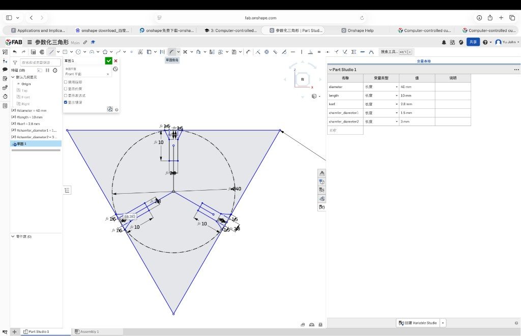
Step 4: Chamfer variables
Square slot corners fought the first dry fit, so I introduced
chamfer_diameter1 and chamfer_diameter2 and applied chamfers at each
slot entry. The goal is a lead-in angle so parts slide together without cracking the plywood
corners.
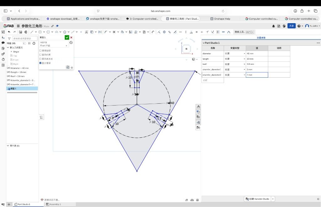
Step 5: Tune chamfer_diameter1
I increased chamfer_diameter1 from 1.5 mm to 3 mm and nudged
chamfer_diameter2 toward 7 mm until the slot mouth looked wide enough for assembly
but still gripped the mating tab. This step is where parametric design paid off: I could iterate
on angles without redrawing the triangle.
Step 6: Tune kerf
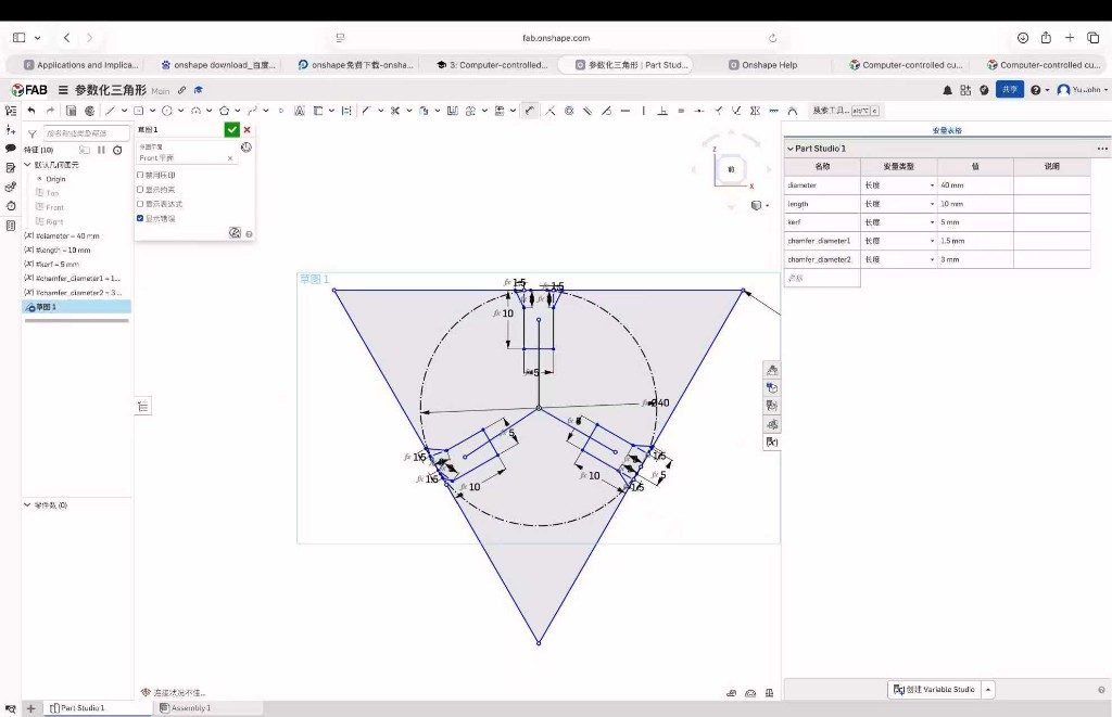
With chamfers settled, I swept kerf around the nominal value to see how slot width
affected fit on real 3 mm stock. Values much wider than 2.8 mm felt loose; narrower values made
hammer-free assembly difficult. I kept 2.8 mm as the production setting for this plywood lot.
Step 7: Export DXF
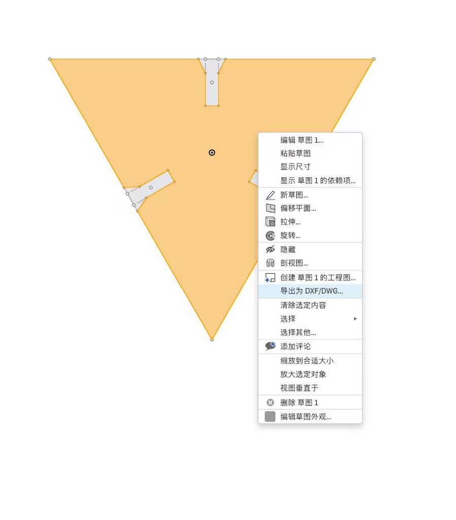
From the finished sketch I right-clicked the face and chose Export as DXF/DWG… for the laser workflow. I exported in millimetres (not centimetres) so the cutter software imported the outline at the correct scale.
Laser cutting
I transferred the DXF to the lab laser, picked cut settings for 3 mm plywood based on our group characterization notes, and ran enough copies of the triangle to build a small 3D assembly. The clip below shows the cut on the machine.
Assembly result
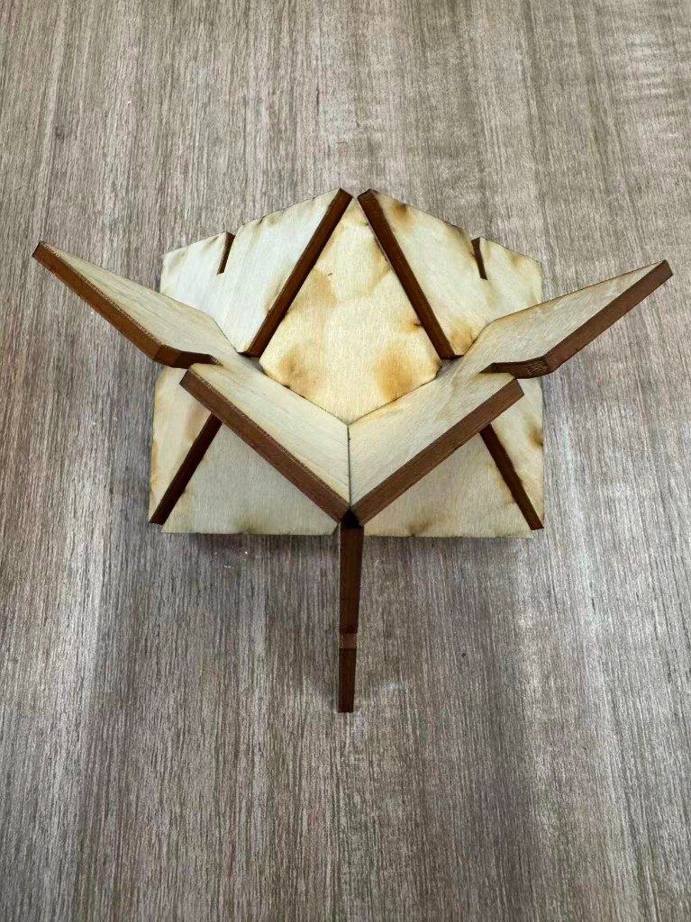
Off the bed I deburred the charred edges lightly, then pressed the identical triangles together through the slots. The chamfers helped more than I expected on the first push. The structure below is one way to stack the same part; the kit can fan flat or build upward depending on how the slots meet.
Vinyl cutter
The individual brief also asks for a vinyl-cutter job. I reused the same
week3-triangle-kit.dxf rather than downloading a sticker file: one triangle outline
with the same slot geometry, sent through Cricut Design Space as a through-cut on adhesive vinyl.
That checks whether the parametric export survives a knife plotter workflow, not only the laser.
Machine and material setup
| Item | Setting used |
|---|---|
| Machine | Cricut at Chaihuo — front-panel Load/Unload and Go controls |
| Software | Cricut Design Space (desktop), paired over USB |
| Cutting mat | StandardGrip green mat, 30.5 cm × 61 cm (12 in × 24 in) |
| Blade | Fine-Point Blade in clamp B |
| Operation | Basic cut (through-cut), single mat, mirror off |
| Stock | Blue adhesive vinyl on carrier sheet (face up on the mat) |
| Source file | Same Onshape export as the laser job — week3-triangle-kit.dxf |
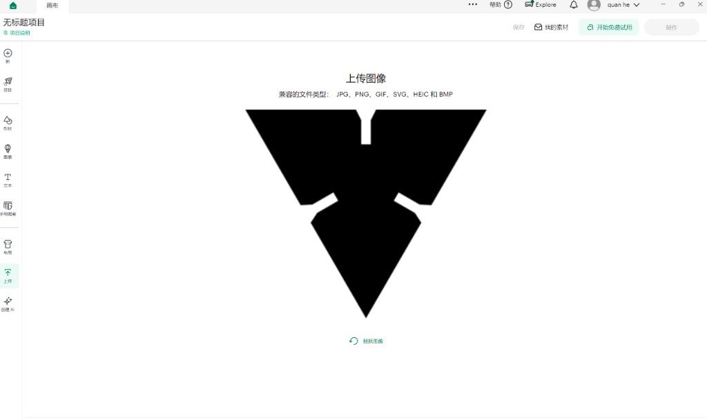
Step 1: Upload the DXF
In Design Space I opened Upload and selected the triangle DXF. The importer accepts SVG, DXF, PNG, and other flat formats; the silhouette arrived as a single closed outline ready for a basic cut.
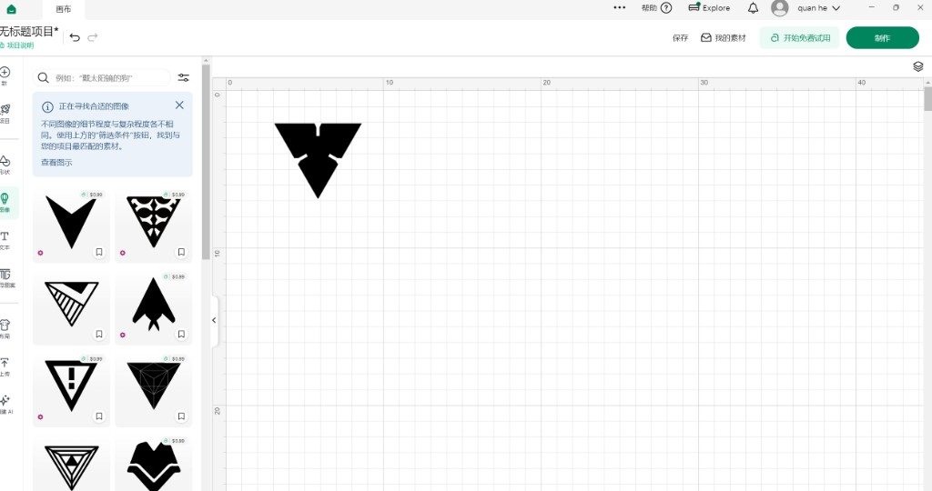
Step 2: Place on the canvas
I dropped the outline onto the grid, confirmed the layer stayed on Basic cut, and left one copy in the upper-left region so rollers would still grip the mat edges during the job.
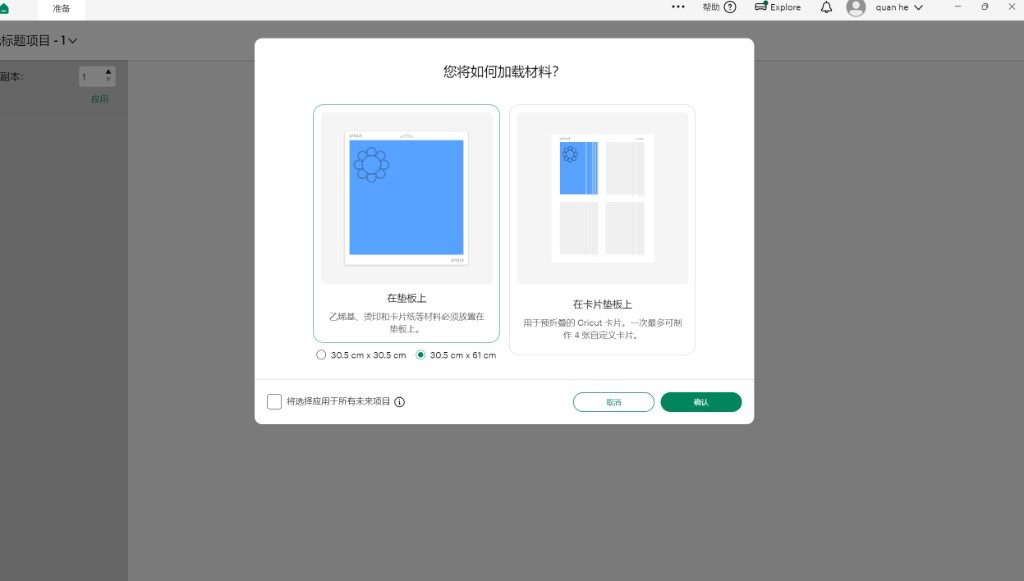
Step 3: Choose mat loading
On Make It I chose On mat (not the card-mat workflow) and confirmed the 30.5 cm × 61 cm StandardGrip size so the virtual layout matched the physical mat on the bench.
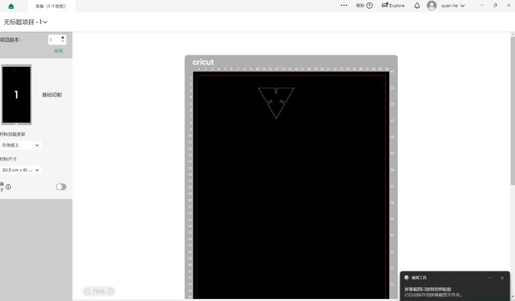
Step 4: Prepare mat preview
The prepare screen shows the triangle nested on the virtual mat with the cut boundary highlighted. I checked mirror was off and only one mat was queued before sending the job.
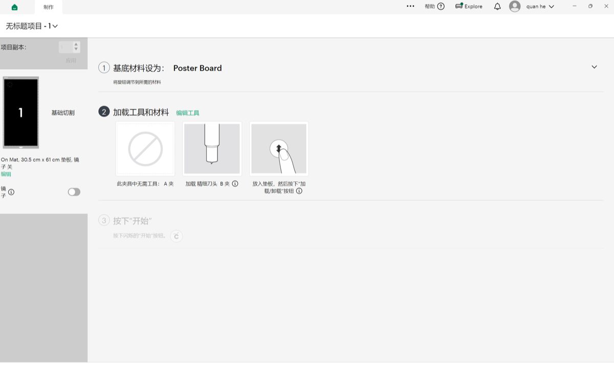
Step 5: Blade and material checklist
Design Space then walked through the on-machine checklist: set the material dial to the vinyl preset, confirm the Fine-Point Blade in clamp B, load the mat until the rollers catch, press Load/Unload, then Go when the prompt unlocks.
Step 6: Cut on the machine
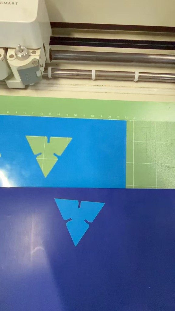
The clip below is the through-cut on the Cricut: the mat advances, the blade traces the triangle outline and slot notches, and the vinyl stays on the carrier until I peel it afterward.
Step 7: Finished vinyl cut
After the job I lifted the cut triangles from the green mat. The slot width matches the same parametric sketch used for laser plywood, which is a quick sanity check that the DXF export did not lose interior features when it moved to a second cutter.
Design files
Reflection
Treating kerf as a real dimension (not a note on the group page) meant I could
regenerate the DXF when our comb test nudged the fit value instead of hand-editing three slots.
Chamfers were the other lesson: parametric sketches only stay pleasant to assemble if you plan
for entry angles, not just nominal slot width. Running the same file on the vinyl cutter showed
that this week is really two CAM paths: laser kerf compensation in Onshape and knife-plotter
presets in Design Space, not two different geometry languages.
The group laser session also made safety part of the cut, not a preamble: ventilation on, fire watch assigned, and material approved before anyone hits start. That checklist sounds bureaucratic until you watch plywood char at the wrong focus height; then operator sign-off feels reasonable.