Week 2 — Computer-Aided Design
Individual assignment
I modeled final-project work in both 2D and 3D this week: Blender for a concept enclosure around the display stack, and LaserMaker for a wooden suggestion-box layout that separates cut and engrave layers before the laser runs in Week 3.
Software choice
Blender is fast for concept iteration. I can block out proportions in edit mode, smooth forms in sculpt mode, and export meshes for fit checks without committing to final wall thickness yet. LaserMaker handles the 2D side: vector layout, boolean nesting, and separate layers for cut versus engrave before anything reaches the laser. The suggestion box panels are cut in Week 3; the vector file itself belongs here as 2D CAD.
2D CAD: suggestion box layout (LaserMaker)
Alongside the 3D shell I laid out a wooden suggestion box in LaserMaker
(意见箱-V1.2.lcpx). The file nests all panels on one sheet: tab-and-slot
walls, a front face with engraved graphics, a back panel with mounting slots, and a small retrieval
door labeled 取件口. I split processes by layer color so cutting and engraving stay predictable
on the machine.
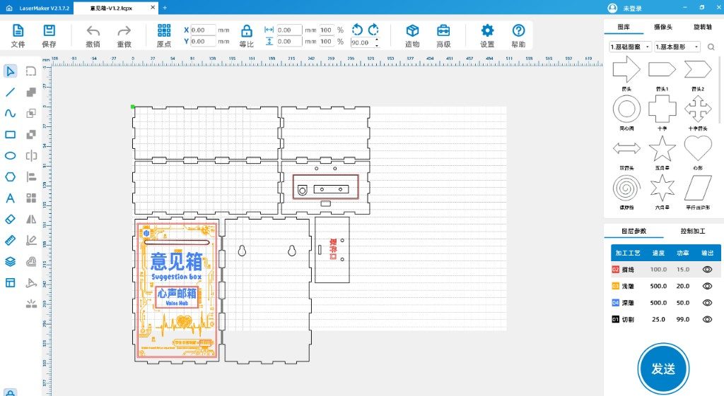
Layer settings I used in this project file:
- 01 切割 (cut): through-cut for outer contours and finger joints.
- 02 描线 (trace): light line work such as the retrieval-port label.
- 03 浅雕 (shallow engrave): background texture on the front panel.
- 04 深雕 (deep engrave): main titles and badge graphics.
This satisfied the Week 2 requirement to model in 2D CAD. I carried the same file into the laser workflow the following week; see Week 3 — Computer-controlled cutting for machine runs, assembly photos, and the finished box.
3D concept: final project enclosure
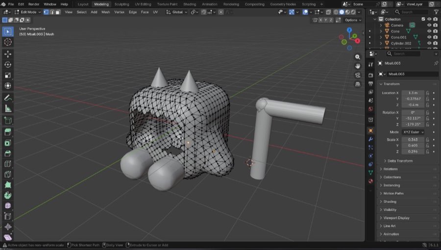
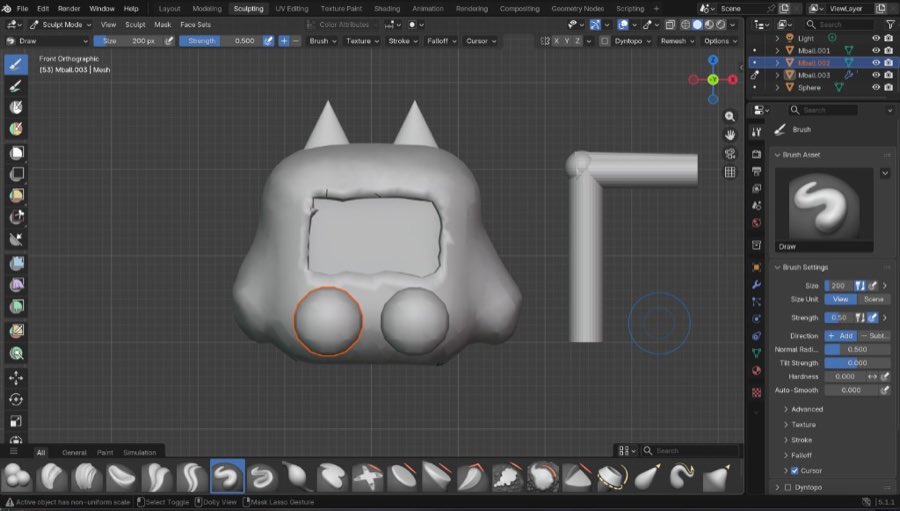
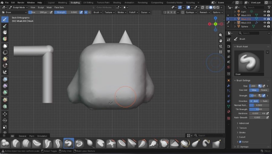
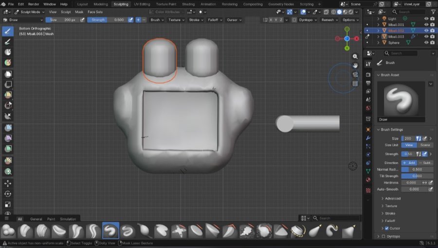
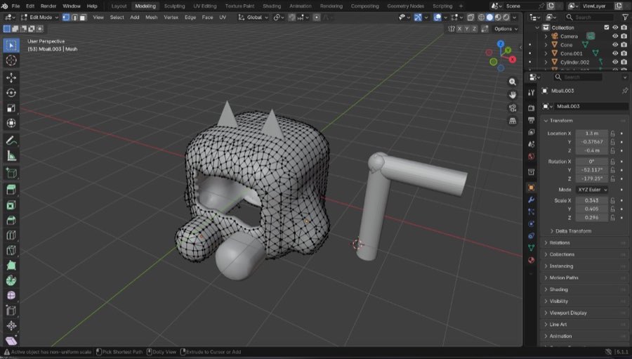
The model includes a front display area, rounded body features, and accessory geometry that helps me evaluate overall proportions and visual identity.
Blender workflow
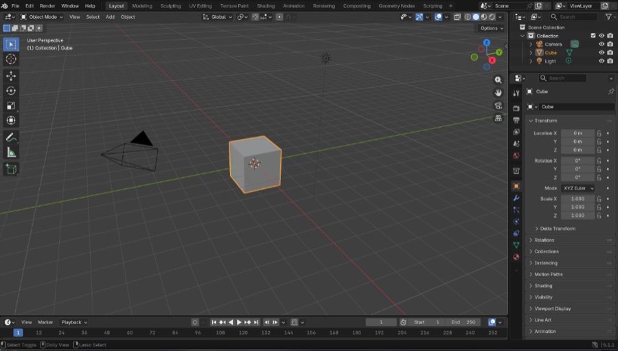
- Opened a clean Blender scene and reviewed default workspace settings.
- Blocked out the basic body and side components using primitive meshes.
- Refined silhouette and major openings in edit mode to establish overall shape logic.
- Switched to sculpt mode to smooth transitions and tune the soft organic form.
- Adjusted details from multiple orthographic views (front, back, bottom).
- Generated final concept views for documentation and future iteration.
Design files and image compression
I compressed documentation images before upload — the early Blender screenshots as .jpg
(each under 100KB), and the later print-process and LaserMaker screenshots re-exported
as compressed .jpg (typically under 120KB each, max width 1400 px).
Design files for this week:
Download Blender concept file — version 1 (.blend)
Download speaker case source — version 2 (.blend)
Download final enclosure mesh — version 2 (.stl)
Download suggestion box 2D source — LaserMaker (.lcpx)
Version 2 is the widened shell with the honeycomb speaker opening on the back. The
.blend file holds the editable mesh used for documentation and further edits; the
.stl is the same geometry exported for Bambu slicing and fit checks. Both correspond
to the printed parts shown below.
From Blender mesh to first physical print
After the Blender concept work above, I exported the shell to Bambu Studio and ran a first full-scale print on the lab Bambu printer. I wanted to check the outer look and whether the internal cavity could host the display stack planned for the final project.
Version 1: slice, print, and inspect
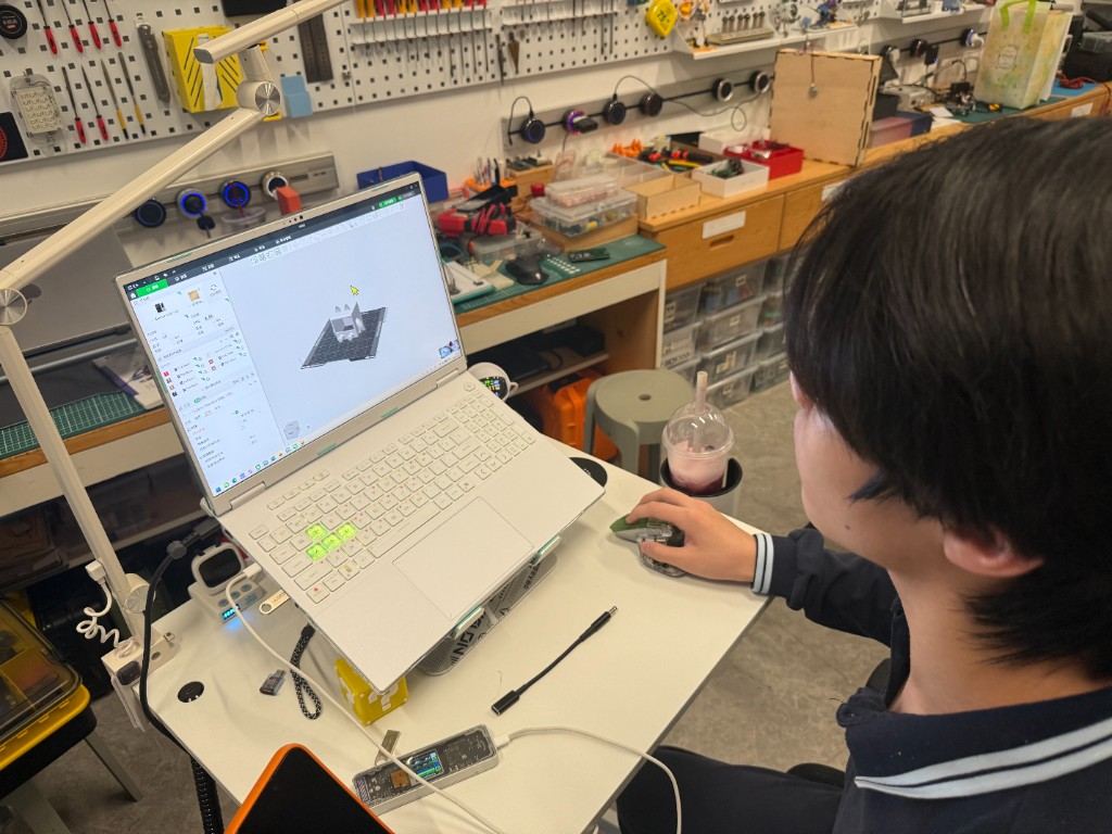
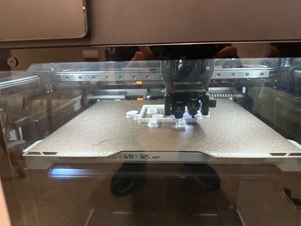
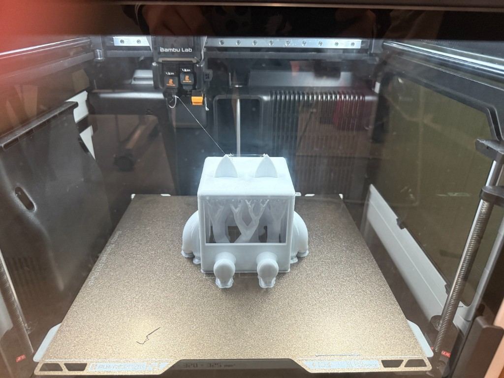
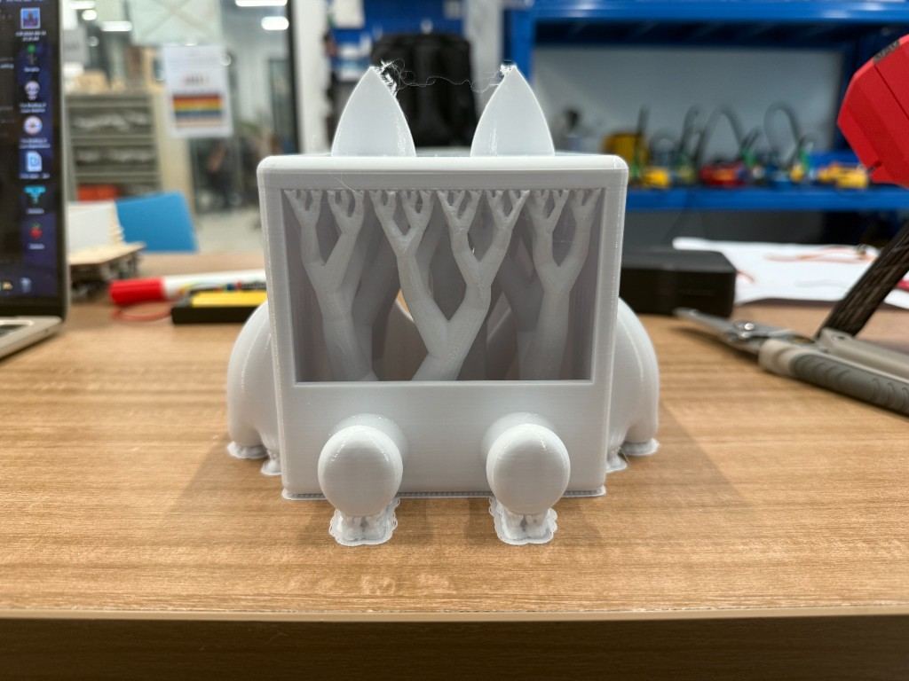
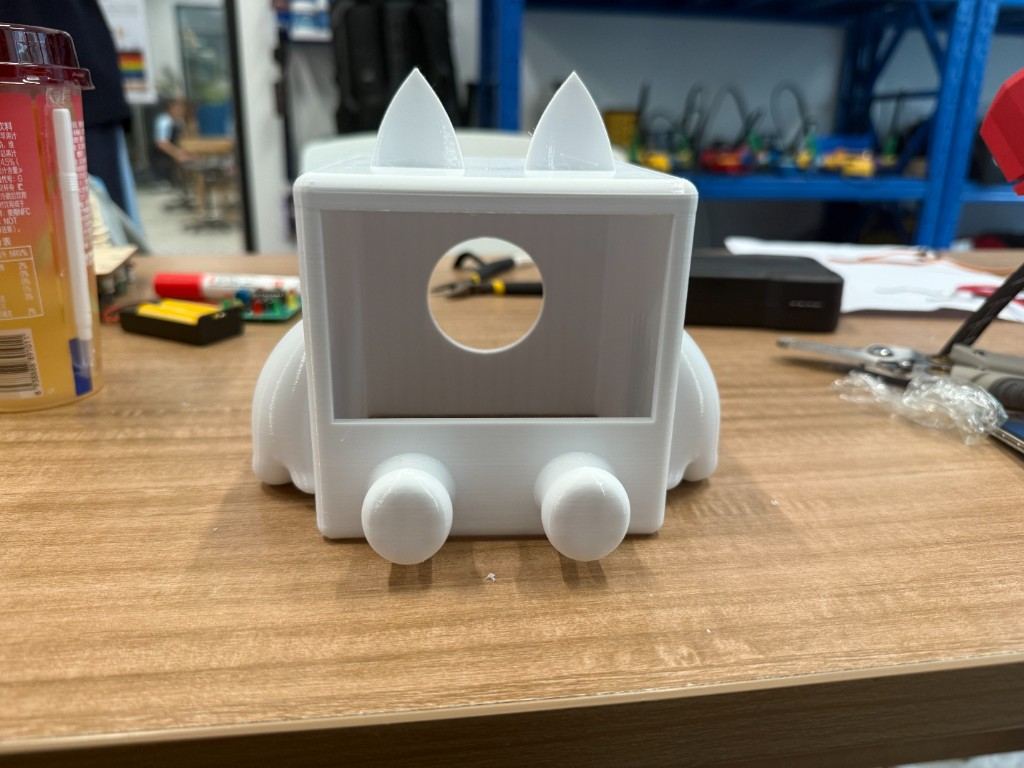
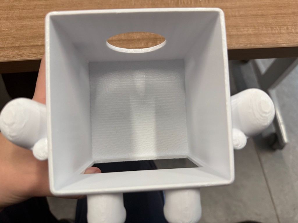
I confirmed the first-version mesh in Bambu Studio, added tree supports for the front opening and overhangs, and started the job. The early layers looked stable, and the full print finished without major warping. Once the part cooled, I removed the internal supports and checked the cavity from the bottom opening.
What version 1 taught me
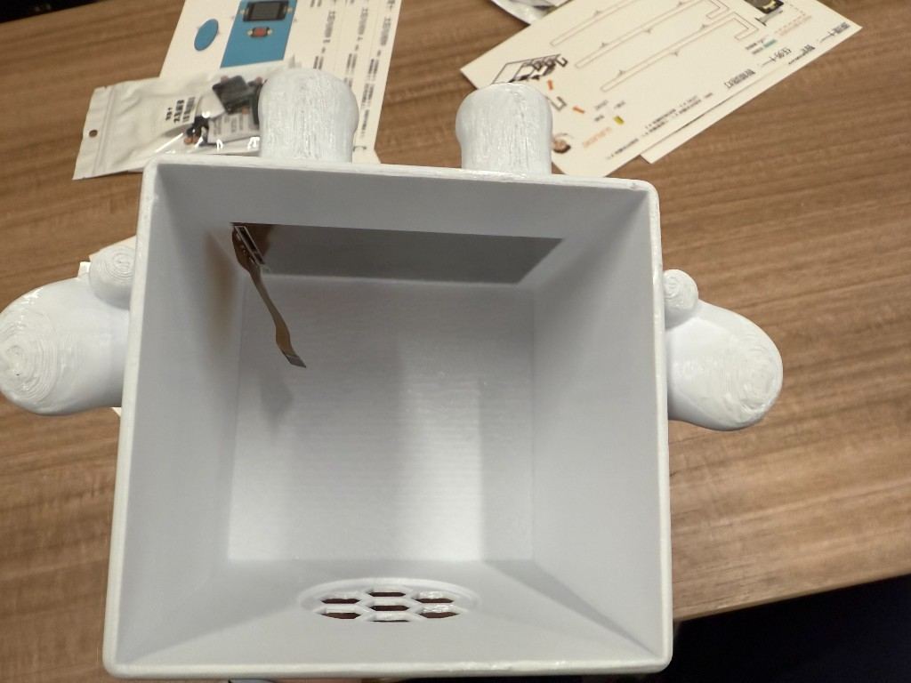
The outer proportions matched what I wanted, but the internal width was too tight. The SPI adapter board for the screen could not sit flat inside the shell without forcing the assembly or blocking the ribbon cable path. That meant the first print was useful as a calibration part, not as the final enclosure.
- Front display opening size was acceptable for the panel itself.
- Internal side clearance needed to increase to fit the SPI adapter PCB.
- Support strategy worked, but post-processing time was longer than expected on the front cavity.
Version 2: wider cavity, speaker grille, and screen fit test
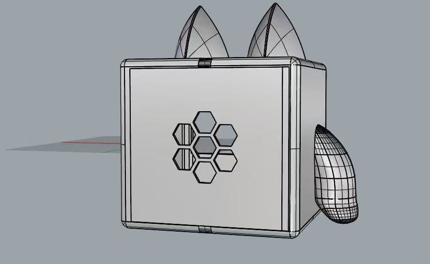
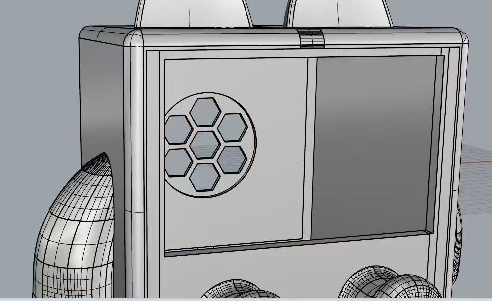
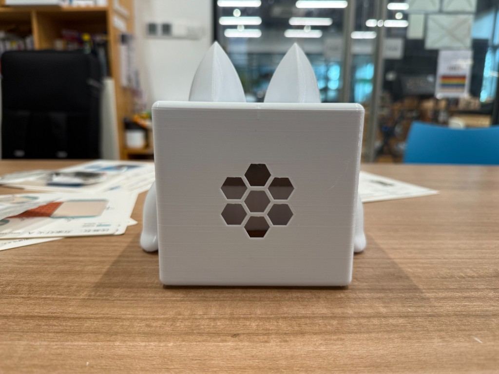
I revised the model in CAD with a wider internal body, kept the same outer character language, and added a honeycomb-style pattern to the speaker opening on the back panel. The pattern breaks up the flat rear surface visually and gives sound a path out without leaving one large open hole.
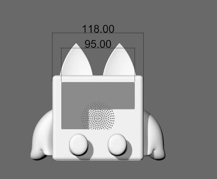
The image below is the dimension drawing for version 2. I marked the overall body width and the back-panel opening width so I could check the shell against the display module and speaker area before sending the revised mesh to the printer.
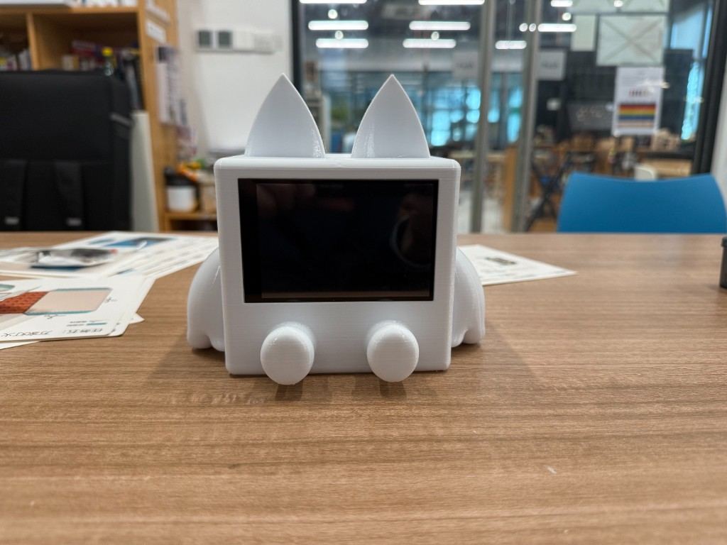
I printed the second version and test-fitted the display module. The panel slid into the front recess cleanly, and the wider interior left room for the SPI adapter board behind the screen.
Reflection
By the end of the week I had fabricatable files, not just screen geometry. Two print iterations showed where the cavity was too tight for the display stack. That saved me from spending another week in CAD only. Separating cut and engrave layers in LaserMaker also set up Week 3: the laser job downstream was mostly parameter tuning, not redrawing geometry.