This week we experimented with different materials and manufacturing processes to improve the components of our final project. Our objective was to find a transparent material that would allow the internal lighting system to be visible, which is a key feature of the interactive climbing wall memory game that forms the basis of our final project.
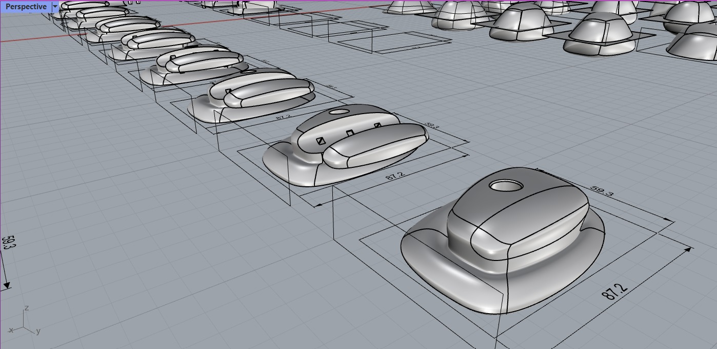
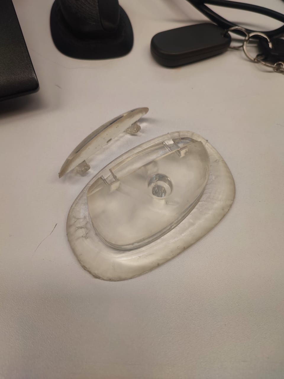
The parts were designed in Rhinoceros 3D and correspond to climbing holds for an interactive children's climbing wall, which is part of our final microarchitecture project.
Resin 3D Printing Process
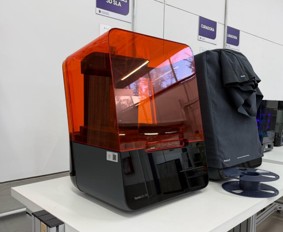
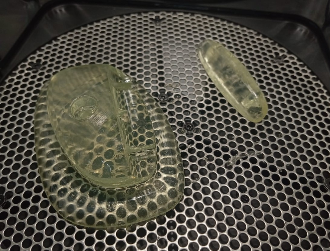
The parts were manufactured using a Formlabs Form 3 resin printer. This machine operates with Stereolithography (SLA) technology, where a laser selectively cures layers of liquid photopolymer resin with high precision. This process makes it possible to produce highly detailed, accurate, and high-quality parts with excellent surface finish and transparency.
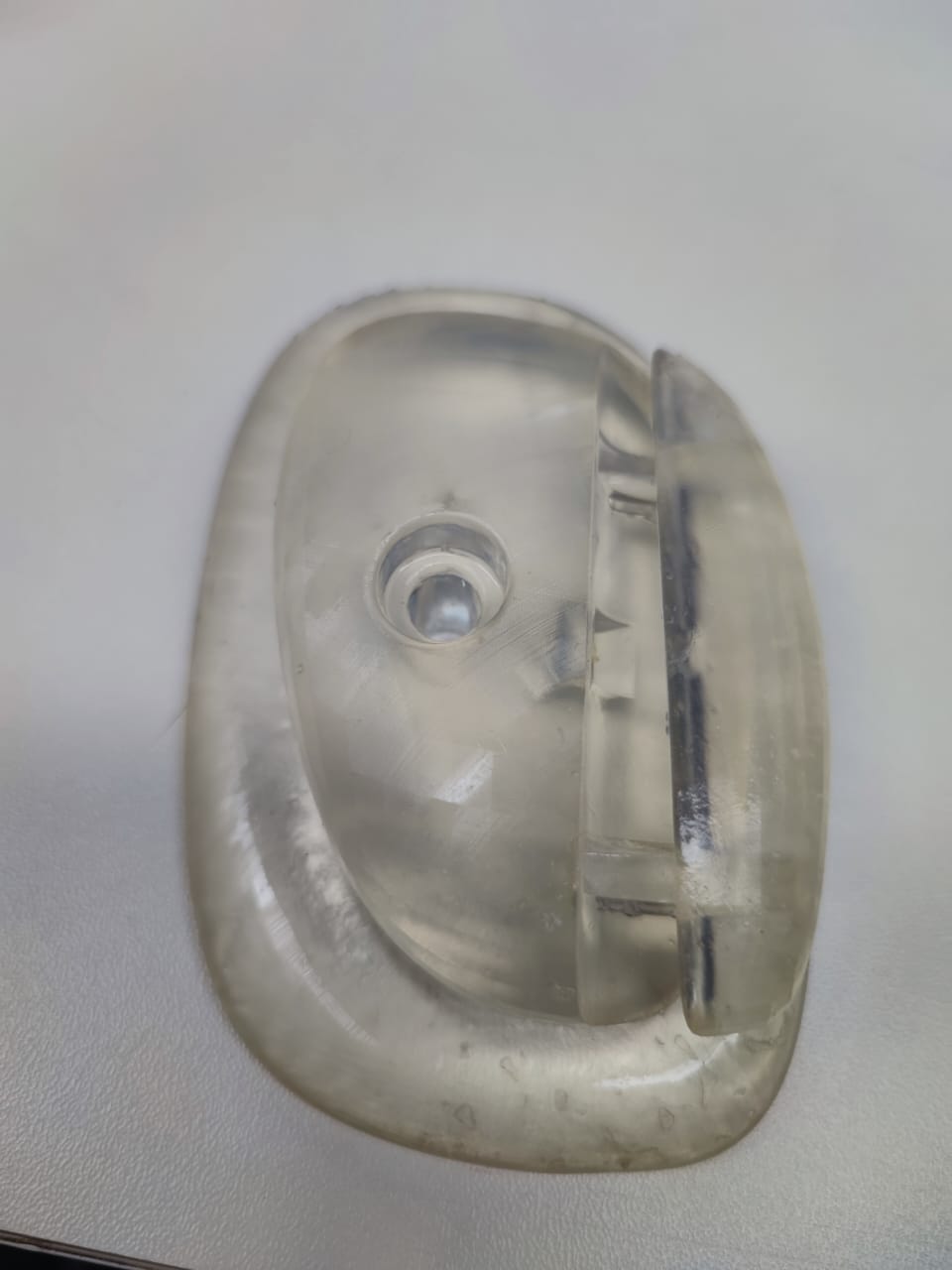
The use of Clear Resin V4 was particularly important for our final project because it allows light to pass through the printed pieces, enhancing the visual effect of the illuminated climbing holds.
Procedure
1. File Preparation
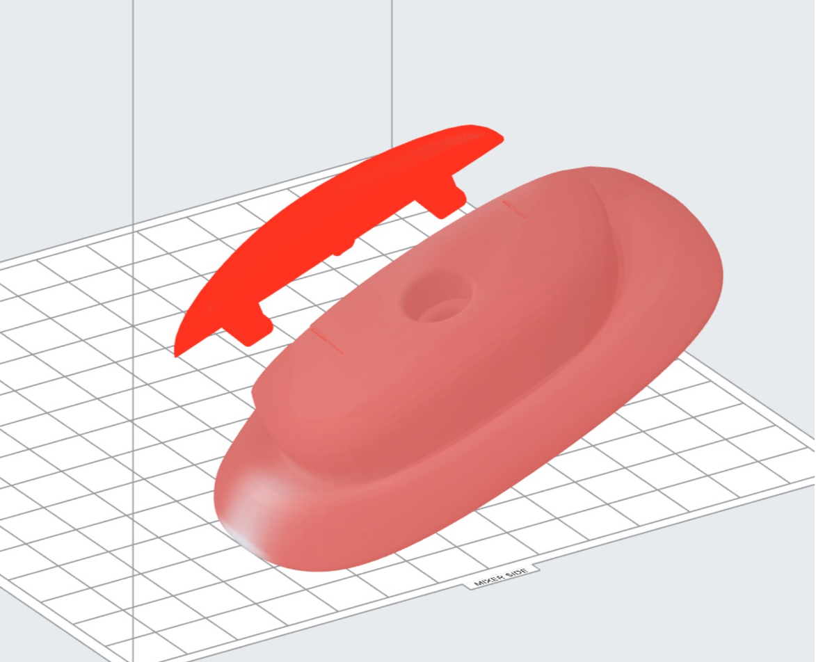
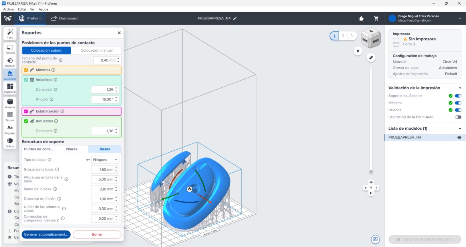
The 3D model was imported into the PreForm software, where the geometry was reviewed and support structures were generated. We selected a support configuration without a base, making it easier to remove the final part without damaging either the build platform or the printed model. The orientation was optimized to improve print stability, detail quality, and overall manufacturing success.
2. Printer Configuration
Next, the appropriate material was selected. In this case, we used Clear Resin V4, which provides rigid parts with high optical clarity. Adaptive quality settings such as layer height and resolution were configured to balance printing time and detail according to the requirements of the model. Before printing, we verified that the resin tank was clean and properly filled and that the build platform was correctly installed.
3. Printing Process
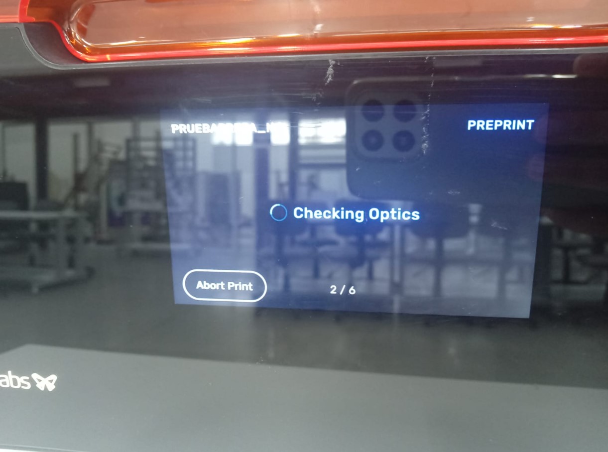
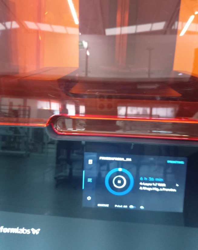
The file was sent to the printer, and the initial stages of the print were monitored. During the process, the laser cured the liquid resin layer by layer until the part was fully completed, achieving the desired level of detail and transparency.
4. Post-Processing
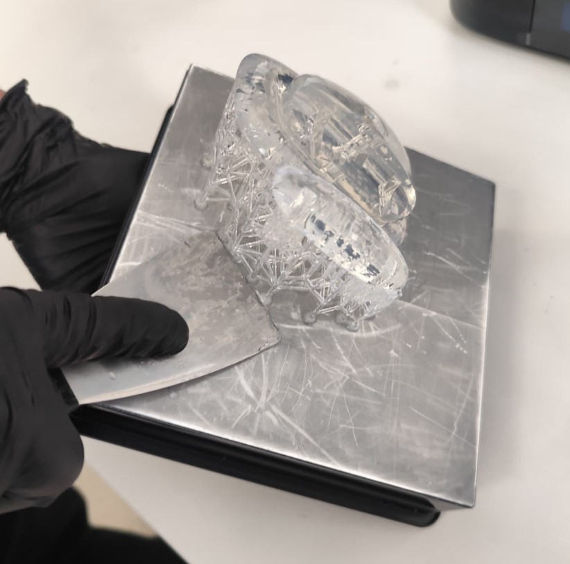
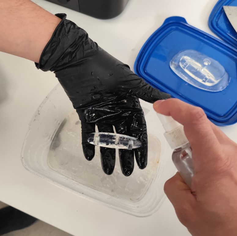
After printing, the part was removed from the build platform using metal spatulas while wearing latex gloves to avoid direct contact with uncured resin residues. The model was then carefully washed with isopropyl alcohol to remove any remaining resin and prepare the surface for the curing process.
5. Curing
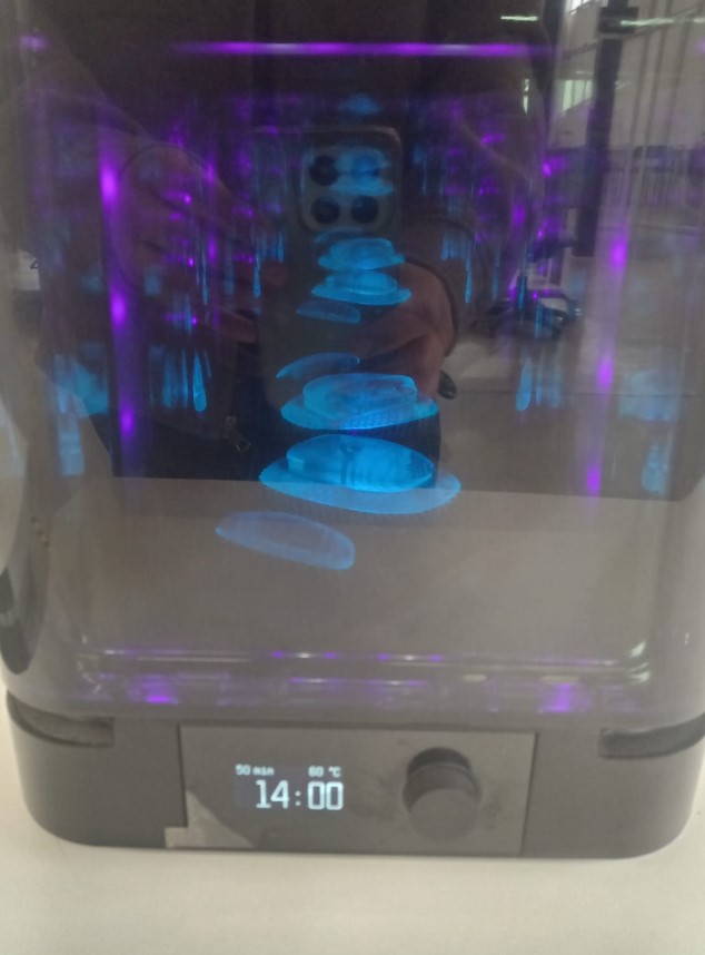
The cleaned part was placed in the curing station at approximately 60°C for a period of 15 to 30 minutes. This stage ensures that the material reaches its maximum mechanical strength and dimensional stability while preserving the transparency of the resin.
Recommendations
We recommend using a support configuration without a base, as it simplifies part removal and reduces the risk of damaging either the build platform or the printed model. Additionally, designing parts with internal hollow sections helps reduce resin consumption and promotes more uniform curing.
During the washing stage, it is advisable to perform a thorough cleaning using isopropyl alcohol in two separate cycles and ensure complete drying using compressed air or controlled ventilation. Proper safety procedures should always be followed, including the use of latex gloves when handling uncured resin.
Results
We successfully manufactured transparent resin parts with a high level of detail and a smooth surface finish. The use of Clear Resin V4 allowed us to evaluate the visual effect of internal illumination, which is a critical component of our final project. The printed climbing holds showed improved aesthetics, greater durability, and a more pleasant tactile experience compared to previous prototypes.
Throughout the process, we identified that insufficient cleaning and drying can result in a sticky surface finish. This observation helped us better understand the importance of following each post-processing step carefully to achieve optimal results.
Conclusions
We concluded that transparent resin 3D printing is an excellent manufacturing method for producing highly detailed and visually attractive components. The process allowed us to understand the importance of each stage, from file preparation to final curing, and how each step directly influences the quality of the final result.
For our final project, the transparent resin parts provide significant advantages because they are stronger, more visually appealing, and allow light transmission, enhancing the interactive experience of the climbing wall memory game.
From an architectural perspective, resin printing represents an interesting technology for producing detailed models and prototypes. However, compared to conventional FDM printing, it is a more expensive process and requires considerably longer production and post-processing times.
Wild Week – Custom Interactive Hold PCB
During this week, I fabricated a custom electronic board for my final project.
The board was designed specifically for the interactive climbing holds and serves
as the interface between the sensing and lighting systems of the wall.
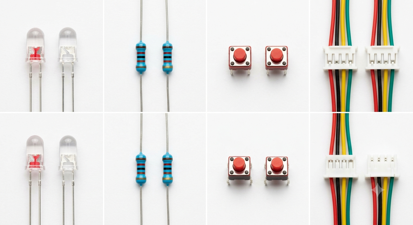
Each board integrates two high-brightness LEDs for visual feedback, a push button
for interaction detection, current-limiting resistors, and an XH2.54 connector
for power and signal distribution. The objective was to create a compact and
reliable electronic module that could be easily integrated inside each climbing hold.
Electronic Components Selection
The first step consisted of defining the electronic architecture and selecting
the components required for each climbing hold. The design includes two LEDs,
resistors, a push button sensor, and an XH2.54 connector for power and signal routing.
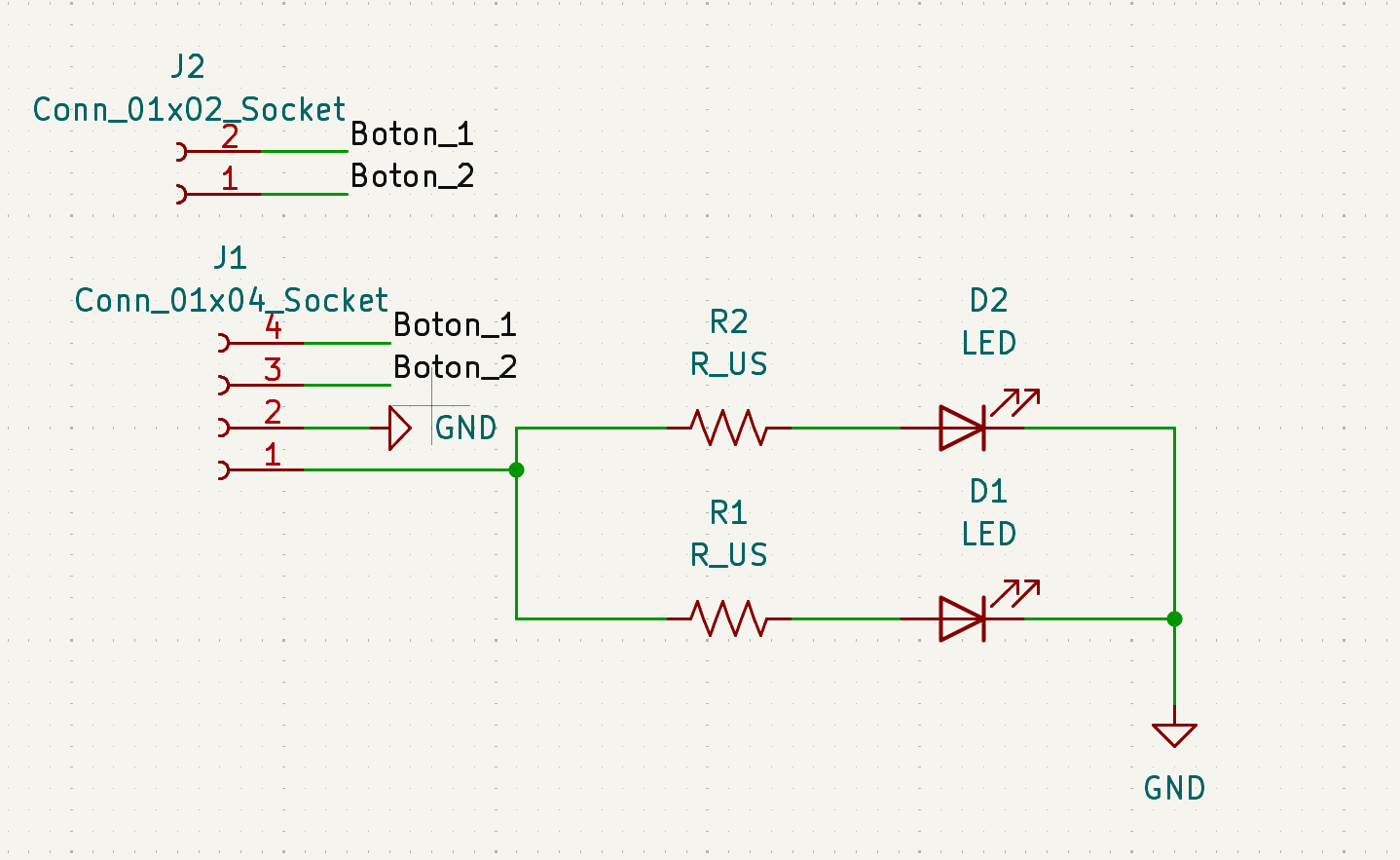
Schematic Design in KiCad
Once the components were defined, the electronic schematic was developed in KiCad.
Labels and net connections were used to organize the circuit and simplify signal routing.
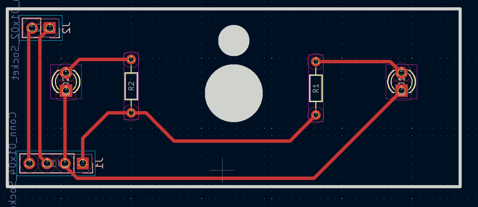
PCB Layout Design
After validating the schematic, the PCB layout was created. Special attention was
given to trace width, component placement, and machining constraints imposed by
the available milling tools.
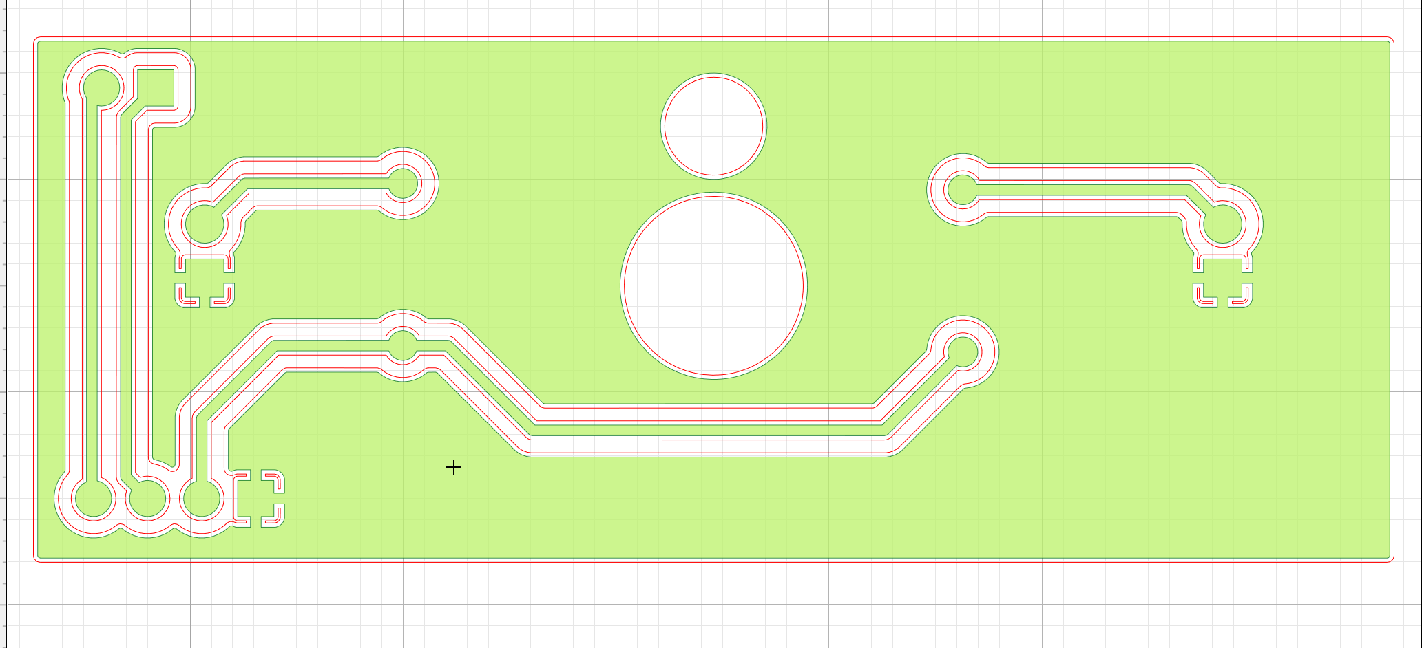
Toolpath and G-Code Generation
The manufacturing files were generated from KiCad and converted into toolpaths
for PCB milling. Parameters such as cutting depth, tool diameter, and isolation
width were configured before fabrication.
PCB Fabrication
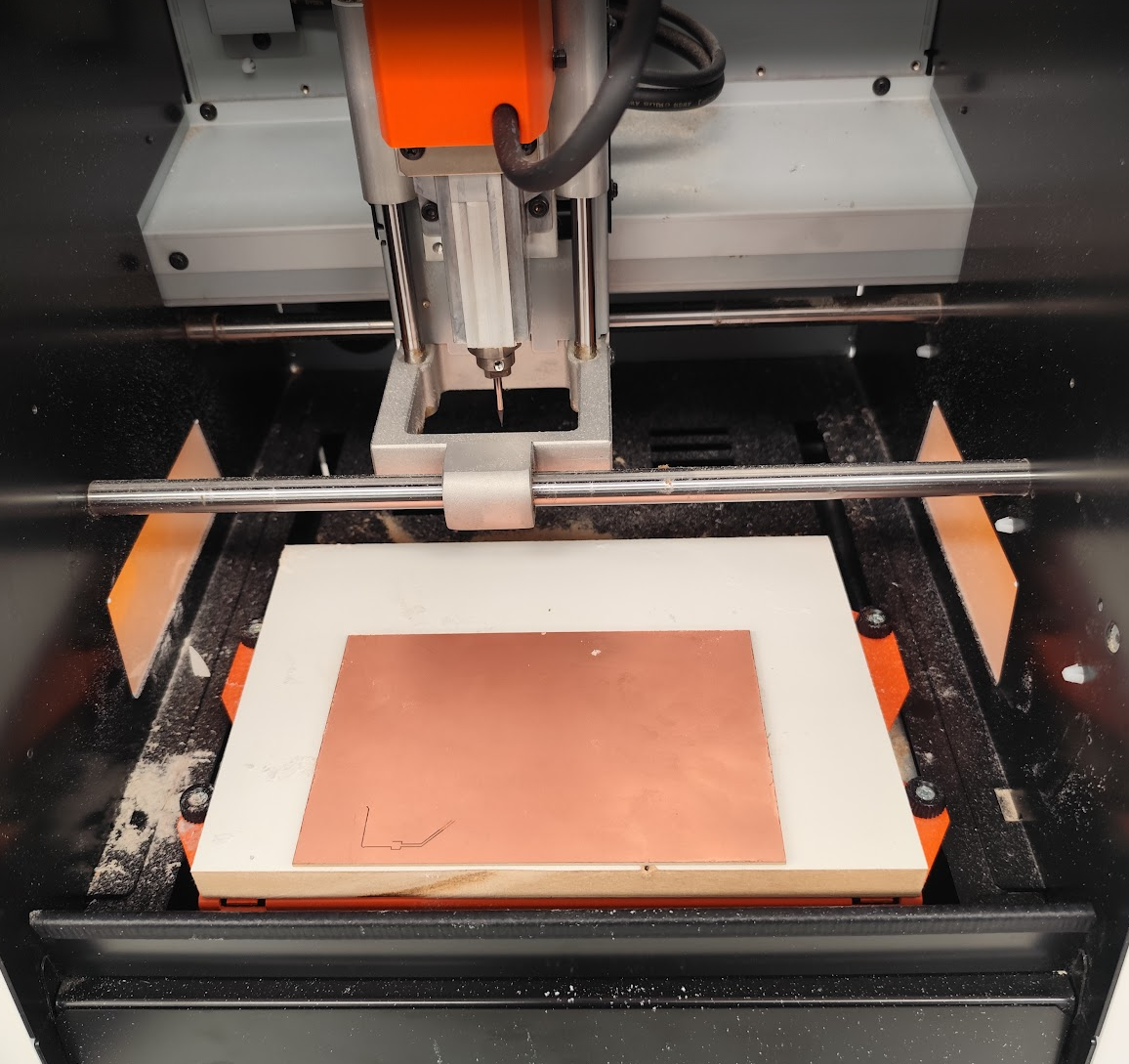
The boards were manufactured using the Roland MonoFab SRM-20 PCB milling machine.
The milling process produced the copper traces and board outline required for
the final assembly.
Component Assembly and Soldering
Finally, all electronic components were soldered onto the fabricated boards.
After assembly, the LEDs, push button, and connector were tested to verify
correct operation before integration into the interactive climbing holds.
Operation of the Tormach 8L CNC Lathe
For the development of this exercise, we used Fusion 360 as the primary software platform. One of the main advantages of Fusion 360 is that it integrates the complete digital manufacturing workflow within a single environment, allowing us to create the CAD model, generate machining strategies, simulate the manufacturing process, and finally produce the G-code required to operate the Tormach 8L CNC Lathe.
1. CAD Design
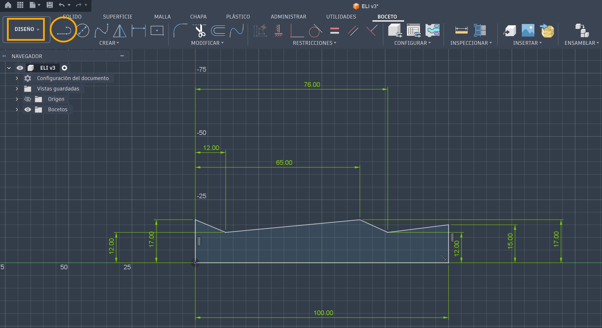
For the design stage, we used the Design Workspace in Fusion 360 to create a conical geometric model. The part was generated using basic modeling tools, primarily the Line and Revolve commands.
Before creating the geometry, we reviewed several design constraints related to machine limitations, material properties, and cutting tool characteristics.
Machine limitations: Since the Tormach 8L is a CNC lathe, machining is performed using only two axes: X (114 mm) and Z (216 mm).
Material: We selected eucalyptus wood, a dense and durable hardwood commonly available in the region and suitable for turning operations.
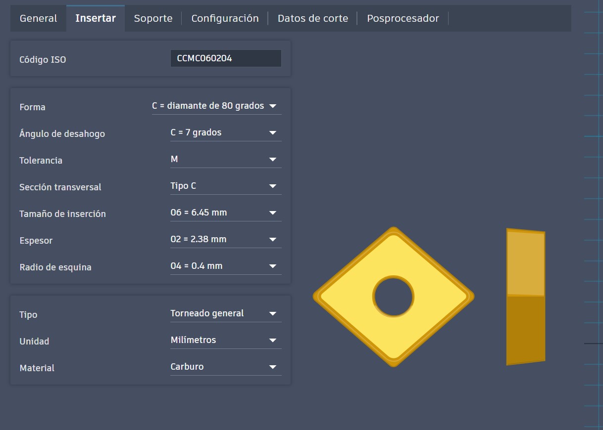
Cutting insert: CCMT insert.
C – 80° rhombic insert geometry.
C – 7° relief angle.
M – Medium dimensional tolerance.
T – Countersunk central hole with screw clamping and chipbreaker geometry.
Once these parameters were established, we designed the component directly in the CAD environment.
Using the Line tool, we created the profile while considering the cutting angles and machining accessibility required by the lathe tool.
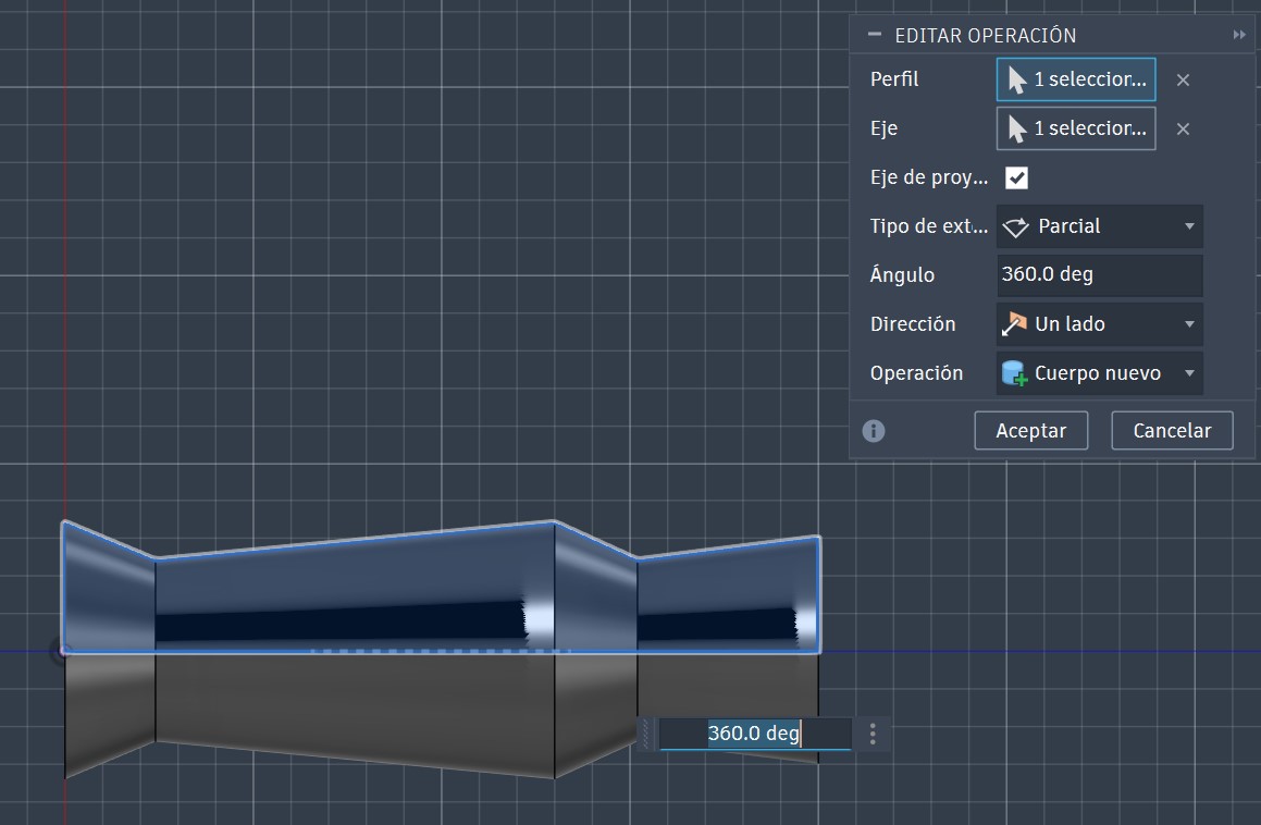
After defining the profile, the Revolve operation was applied to generate the complete three-dimensional model by rotating the profile around its central axis.
Once the geometry was completed, we moved to the manufacturing stage.
2. CAM Manufacturing Setup
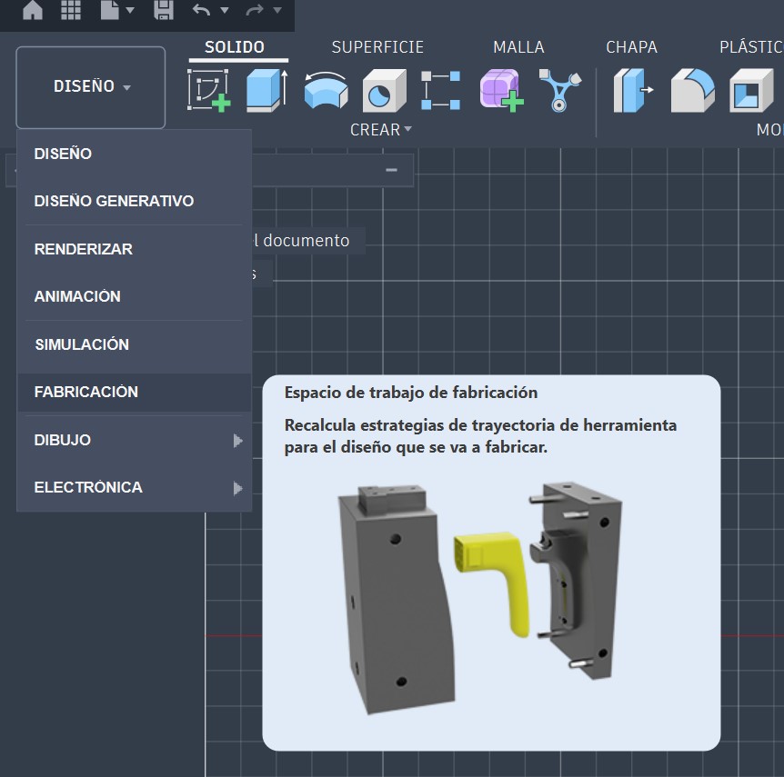
By switching from the Design workspace to the Manufacturing workspace, Fusion 360 provides access to all machining strategies and machine configurations.
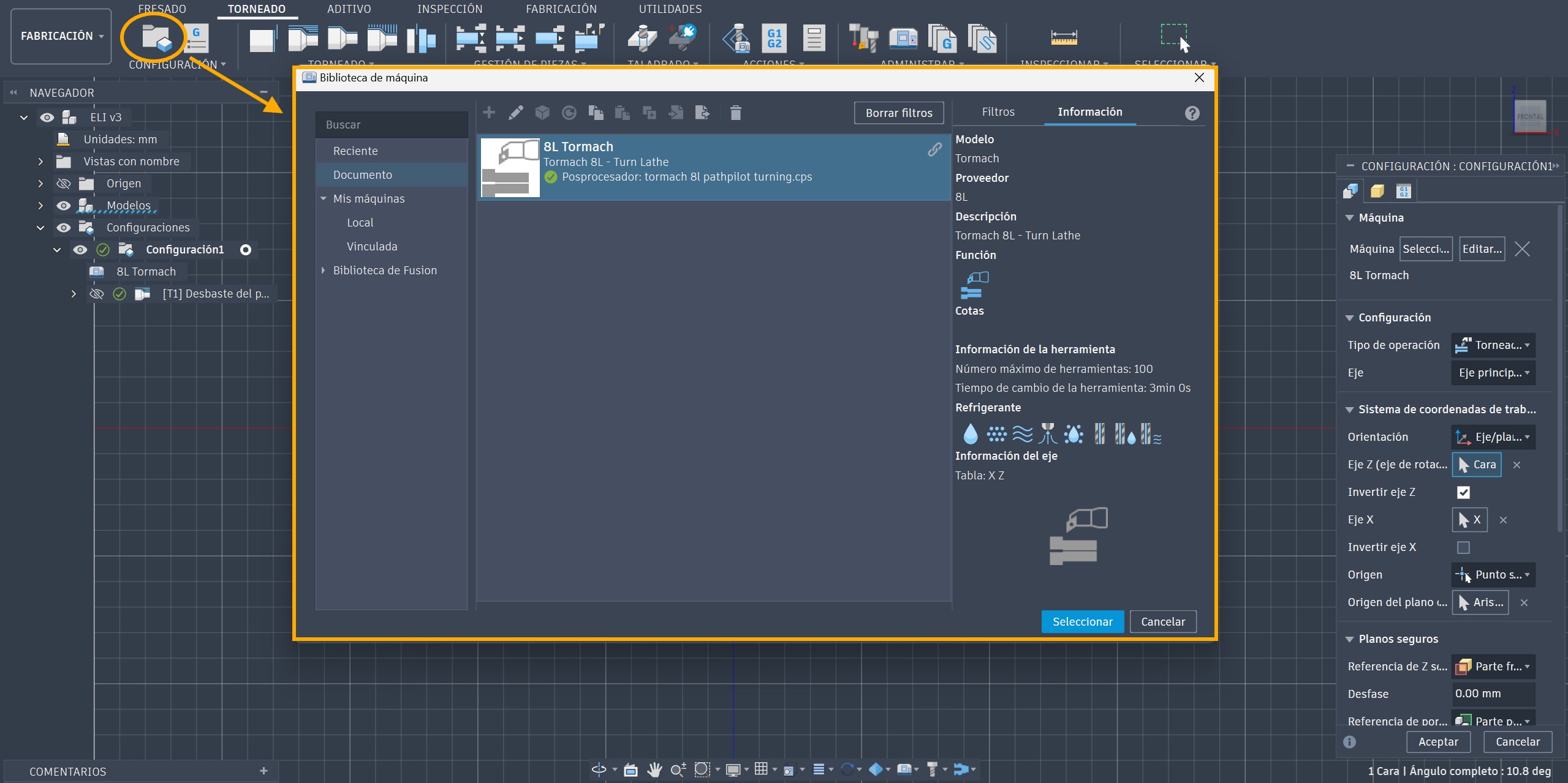
Inside the Manufacturing workspace, we selected the Tormach 8L CNC Lathe directly from the machine library available within Fusion 360.
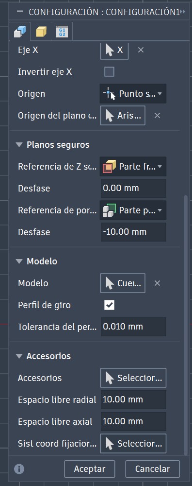
The machine setup allows us to define:
Part orientation relative to the machine coordinate system.
Safety clearances and machining tolerances.
The workpiece origin (X0, Z0).
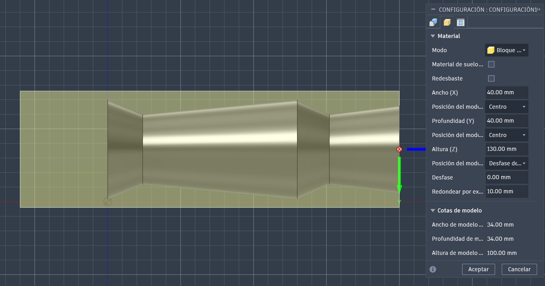
The stock dimensions were also specified according to the dimensions of the eucalyptus wood blank.
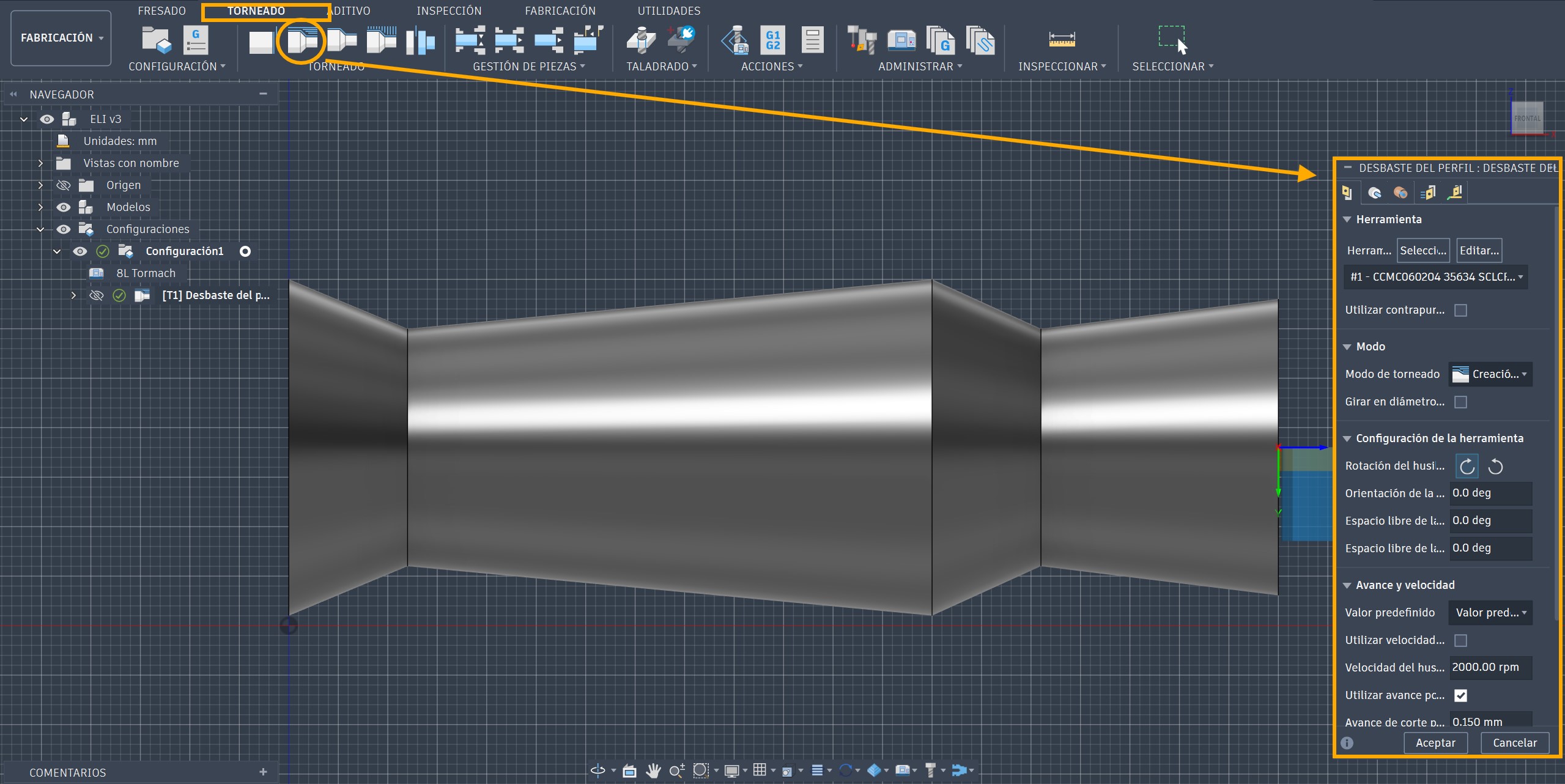
After completing the setup, we selected the Turning machining strategy and chose a Roughing Profile operation to remove the bulk material.
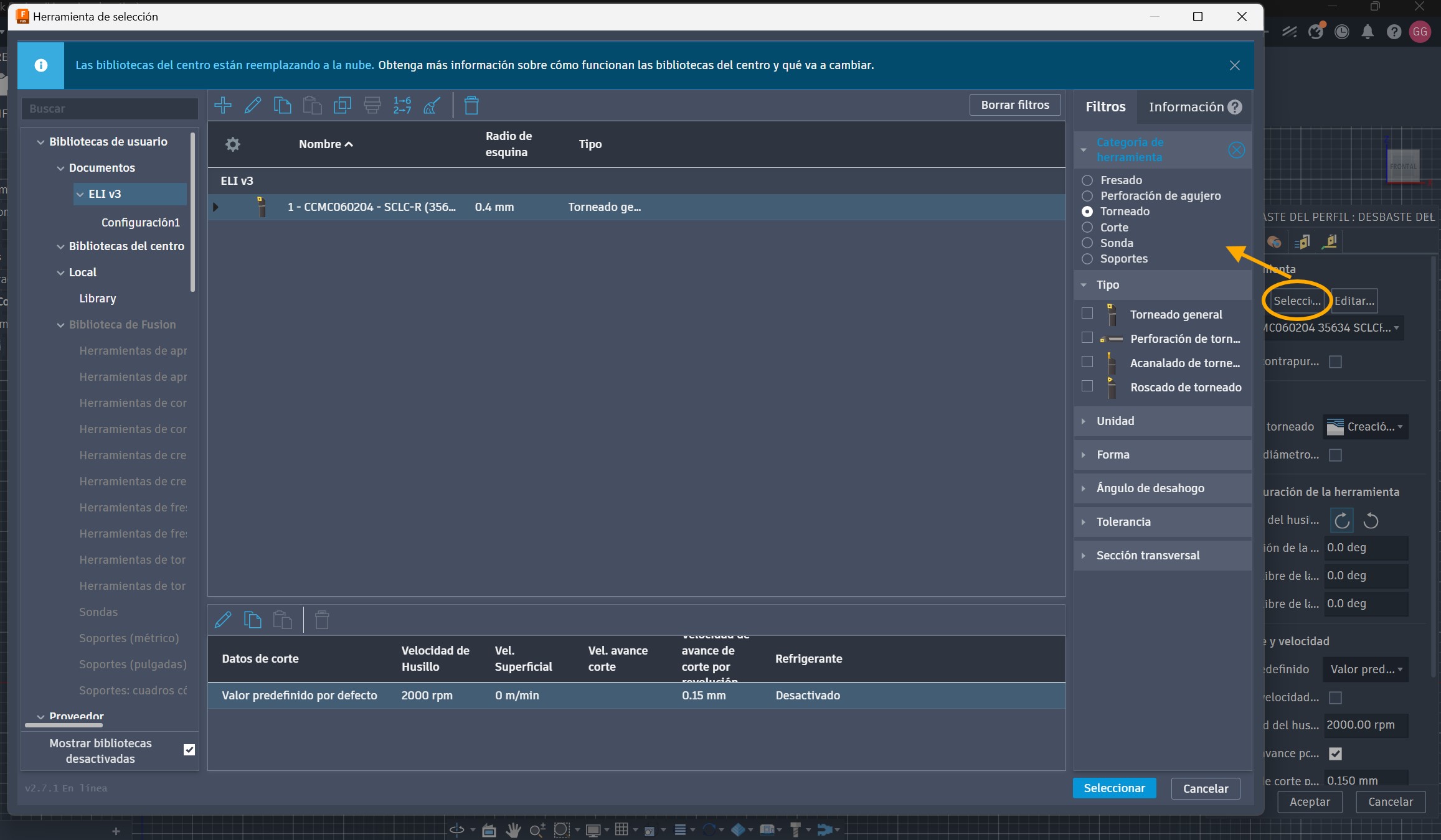
The first step was selecting the cutting tool that would be used during machining.
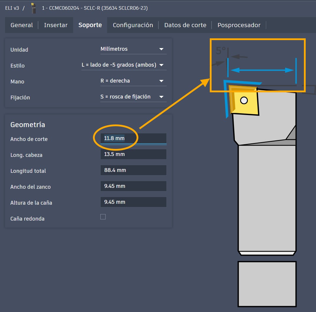
Since the required tool was not available in the default Fusion 360 library, we created a custom tool using the CCMT insert specifications previously defined.
Fusion 360 provides interactive parameter descriptions that simplify the creation of custom tools and ensure that all manufacturer specifications are entered correctly.
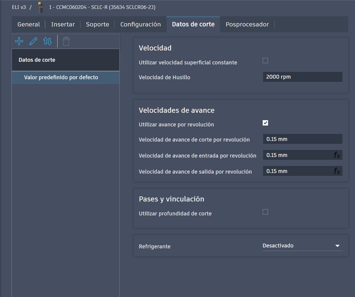
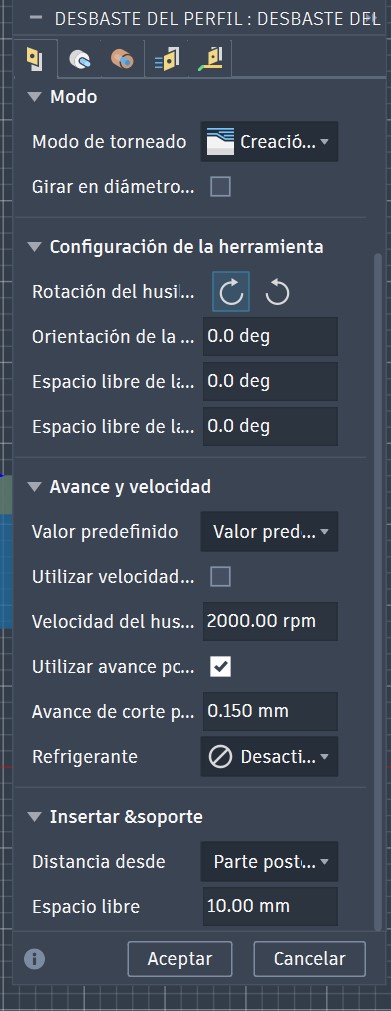
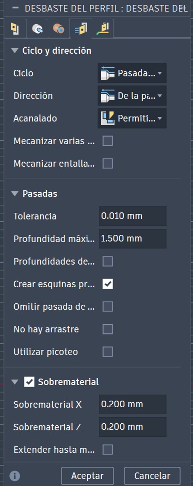
Next, we configured the spindle speed, feed rates, and cutting parameters according to the machining characteristics of eucalyptus wood.
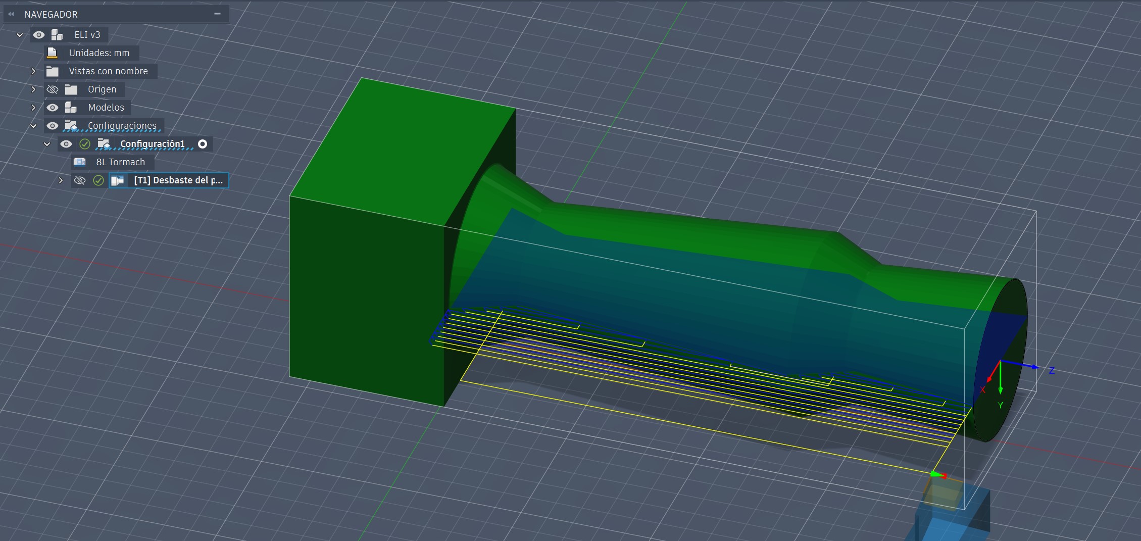
Once the tool and machining parameters were defined, Fusion 360 automatically generated the toolpath. We carefully reviewed all dimensions and machining conditions before proceeding.
The software automatically generated a visual representation of the machining operation, allowing us to verify that all settings were correct before simulation.
3. CAE Simulation
One of the major advantages of Fusion 360 is its ability to automatically simulate the complete machining process using the machine and tool parameters previously defined.
The simulation allows us to verify machine movements, tool behavior, and material removal before any physical machining takes place, significantly reducing the risk of errors.
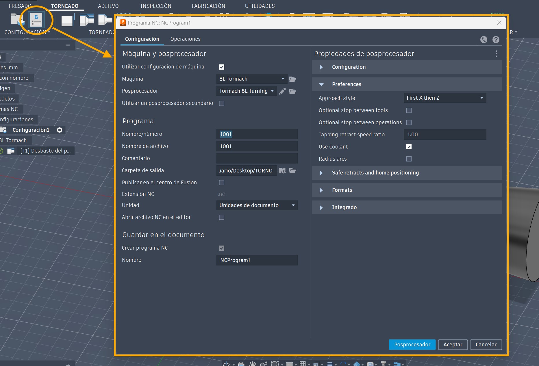
After validating the machining strategy through simulation, we proceeded with post-processing. Fusion 360 generated the final G-code by selecting the appropriate machine and post-processor configuration.
4. Machining on the Tormach 8L
Before running the program, the machine was powered on and the initial machine setup was completed.
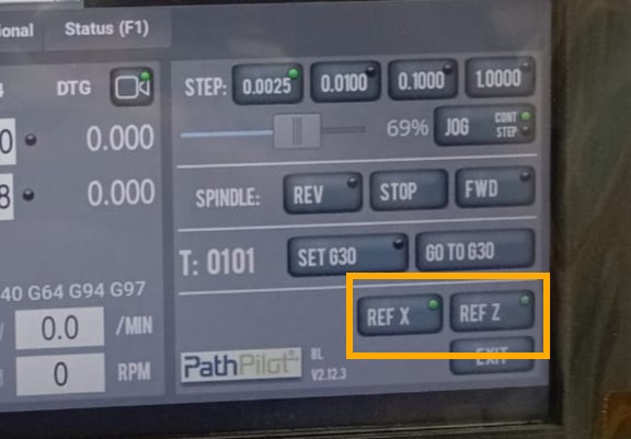
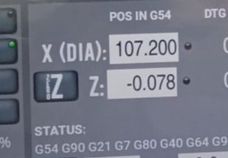
The X and Z reference positions were established using reference points located outside the machining area.
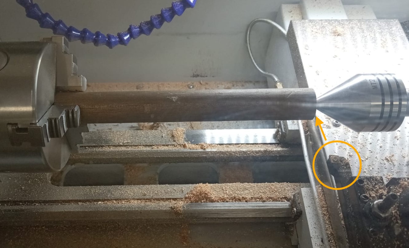
The workpiece origin (0,0) had already been defined in Fusion 360. Therefore, we only needed to align the machine coordinates with the material reference point.
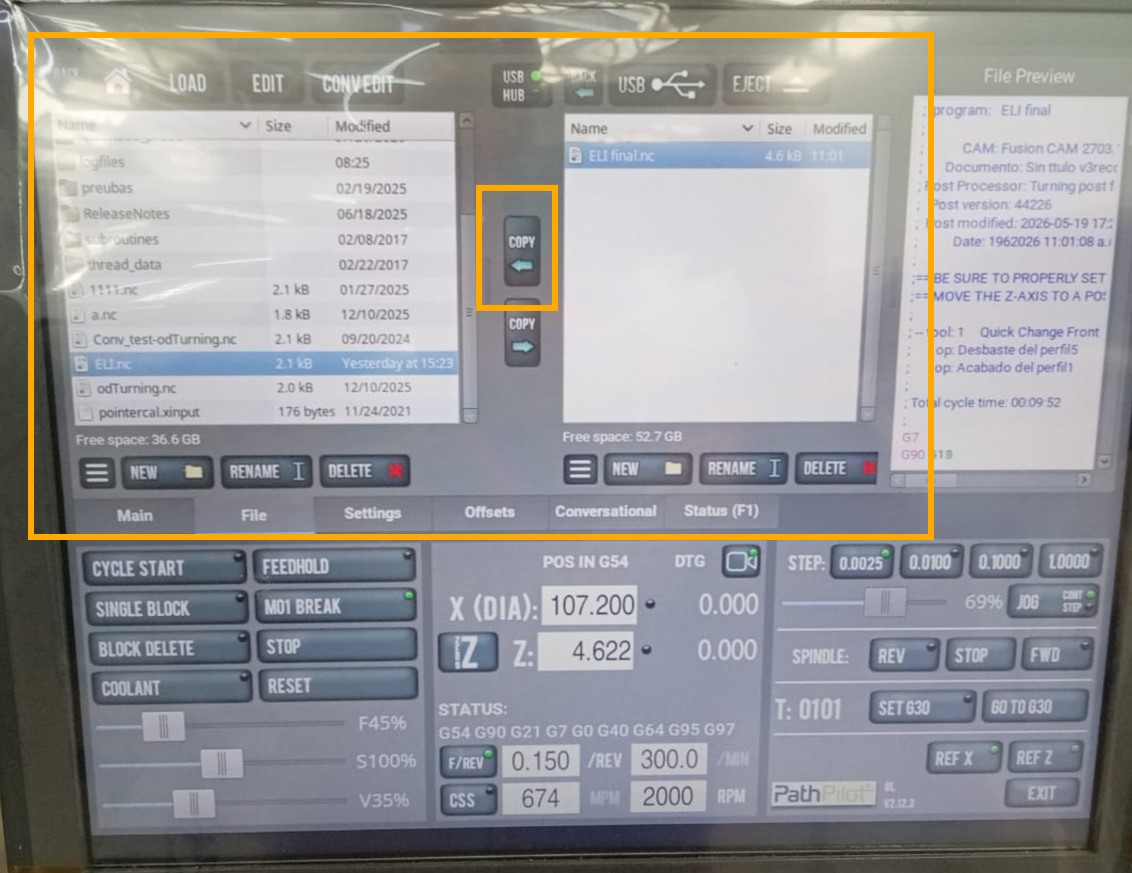
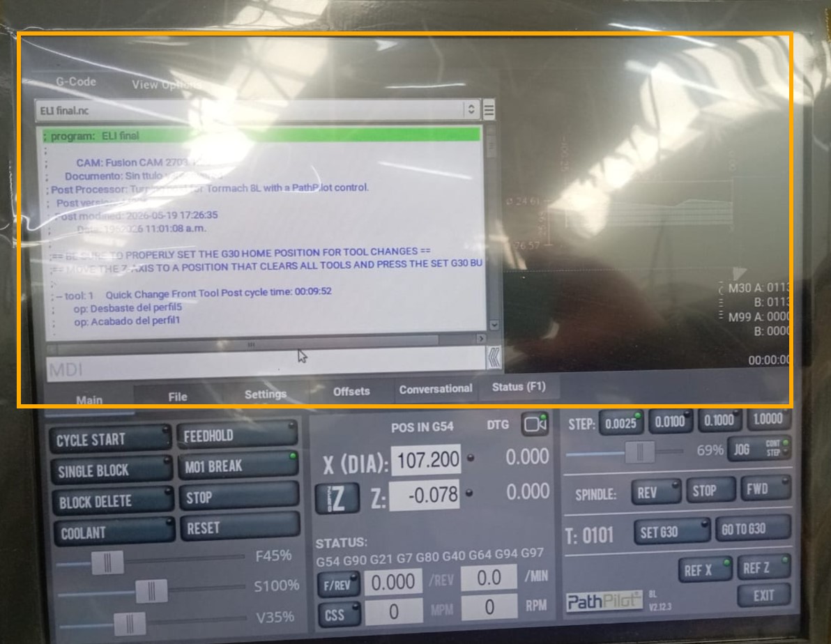
Once all machine parameters were verified, we imported the generated G-code into the Tormach controller using a USB drive.
The controller displayed both the G-code and the machining simulation, allowing a final verification before execution.
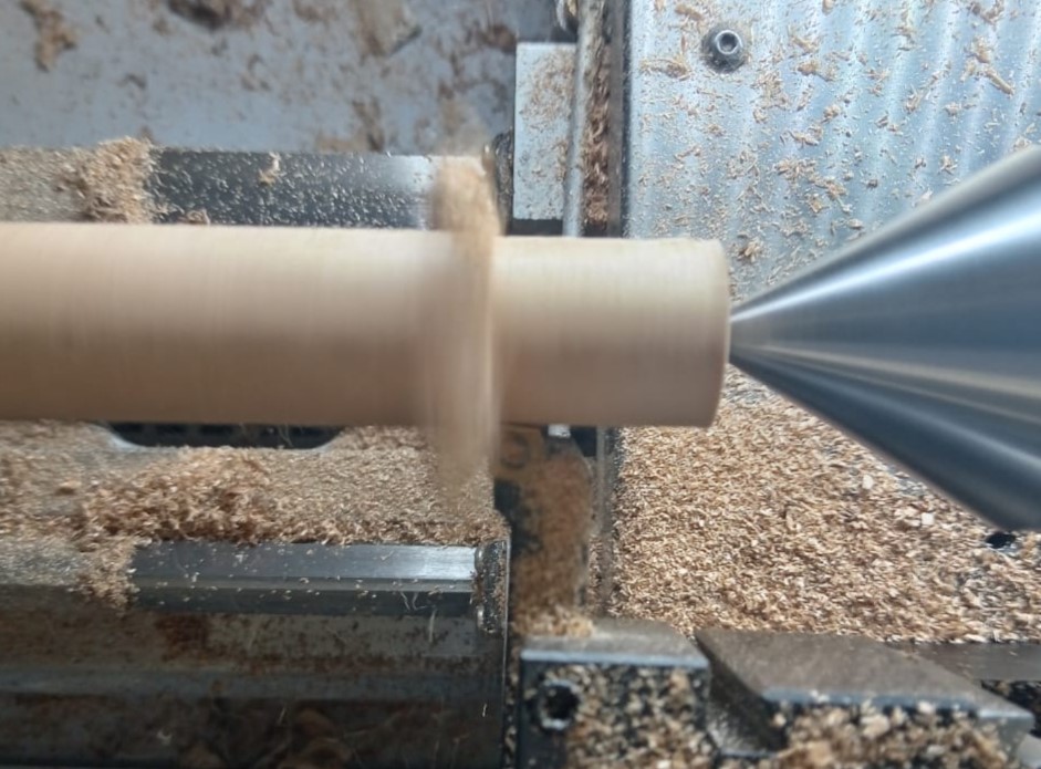
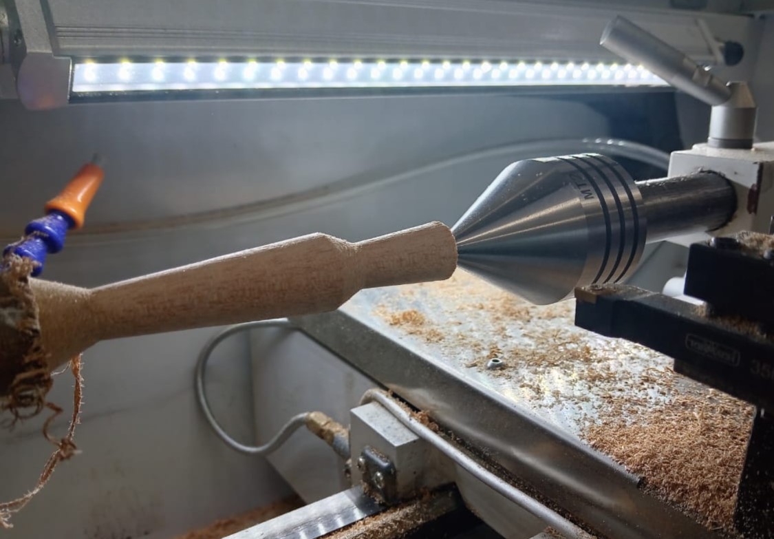
After confirming all parameters, we executed the machining operation and produced the final component.
Conclusions
This exercise allowed us to understand the complete digital manufacturing workflow for CNC turning, from CAD modeling and CAM programming to simulation and physical machining on the Tormach 8L.
We verified the importance of properly defining machining parameters, tool geometry, feed rates, and spindle speeds, as these variables directly influence the quality and precision of the final component.
The integration of CAD, CAM, and CAE tools within Fusion 360 significantly simplifies the manufacturing process by allowing design validation and machining simulation before production.
Finally, the Tormach 8L demonstrated its capability to accurately machine hardwood materials such as eucalyptus, producing precise and repeatable results while providing valuable experience in CNC turning operations.