Design, Construction, and Wireless Connection of ESP32 Nodes
During this week at Fab Academy, we learned how to design, build, and connect
two wireless nodes using ESP32 boards.
Through this practice, we explored how devices can communicate using a
WiFi telecommunication network created directly by one of the nodes.
The system integrates local inputs,
local outputs, and
wireless communication between both devices.
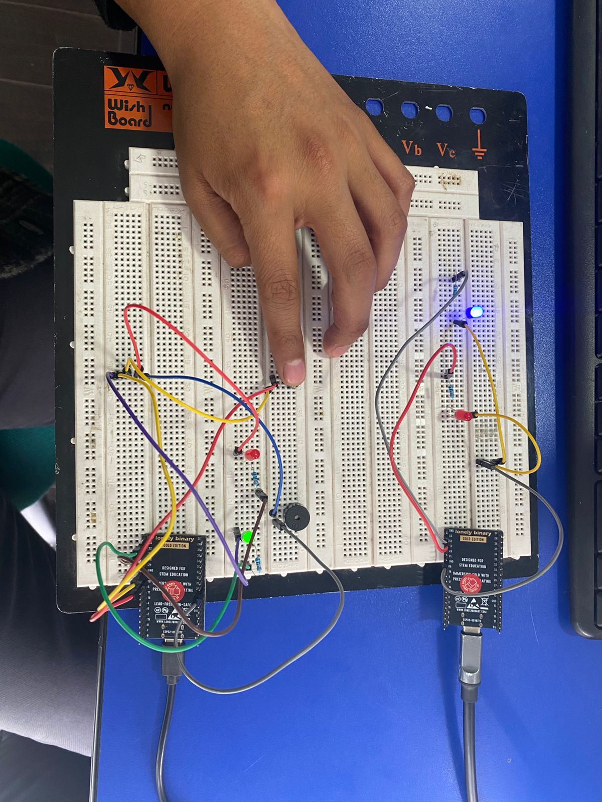
One ESP32 worked as a transmitter node with a push button, LEDs, and a buzzer,
while the second ESP32 functioned as a receiver node and WiFi access point using
SoftAP mode
In this practice, we designed, built, and connected two
ESP32 wireless nodes to demonstrate communication between devices
using a telecommunication network.
Node A was configured as the transmitter node with a push button,
two LEDs, and a buzzer as local devices.
Node B functioned as the receiver and WiFi access point using
SoftAP mode.
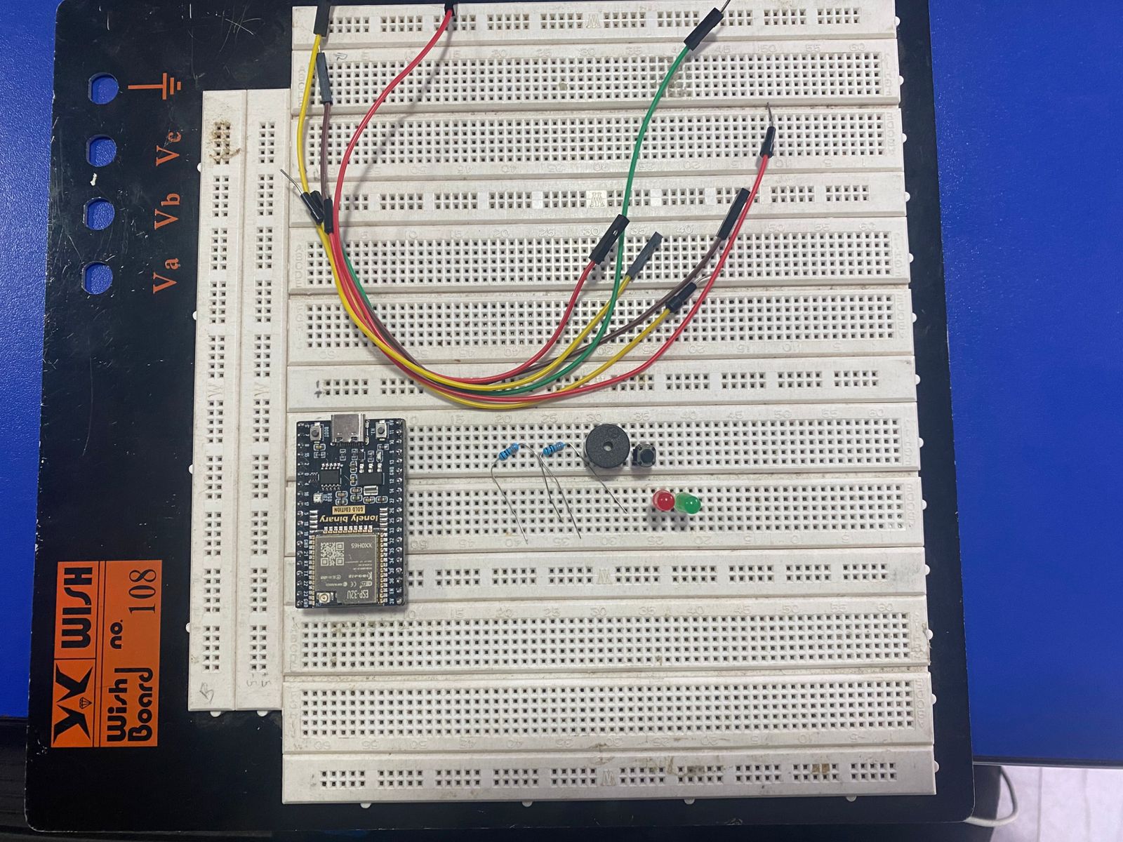
Materials
General Materials
2 ESP32 development boards
2 breadboards
Jumper wires
2 USB cables
Node A Materials
1 ESP32
1 push button
1 red LED
1 green LED
2 resistors (330 Ω)
1 buzzer
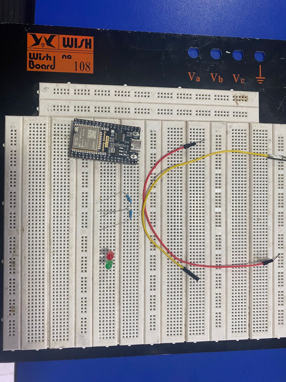
Node B Materials
1 ESP32
1 red LED
1 green LED
2 resistors (330 Ω)
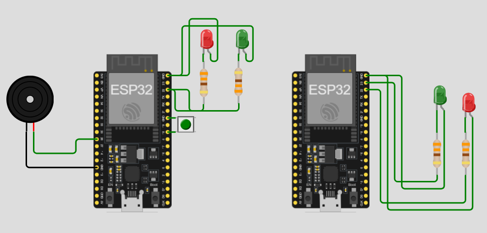
Connections
Node A
Node A was configured with a push button as local input,
two LEDs as local indicators, and a buzzer as sound output.
Push Button
One terminal connected to GND
The other terminal connected to GPIO 18
Red LED
Long leg connected to a resistor
Resistor connected to GPIO 22
Short leg connected to GND
Green LED
Long leg connected to a resistor
Resistor connected to GPIO 23
Short leg connected to GND
Buzzer
Positive terminal connected to GPIO 26
Negative terminal connected to GND
Node B
Node B was configured with two LEDs that worked as remote indicators
of the state received through the network.
Red LED
Long leg connected to a resistor
Resistor connected to GPIO 22
Short leg connected to GND
Green LED
Long leg connected to a resistor
Resistor connected to GPIO 23
Short leg connected to GND
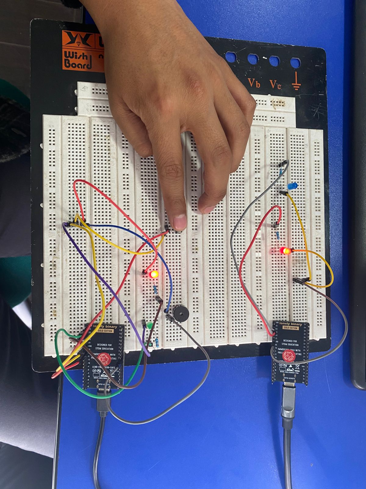
Node A and Node B
Implemented Codes and System Development
To develop this assignment, we first defined the system architecture using
two ESP32 nodes.
Node B was configured as the receiver node and wireless access point,
while Node A was configured as the transmitter node with local inputs and outputs.
In the first stage, we assembled the physical connections for Node A, integrating
the push button, LEDs, and buzzer. Then, we programmed the ESP32 to connect to the
wireless network created by Node B, detect button presses, and alternate between
ON and OFF states.
Each state change updated the local LEDs, briefly activated the buzzer, and sent
a wireless message to the receiver node through an
HTTP request.
Afterward, we assembled Node B with two LEDs and programmed it to work as an
HTTP server and WiFi access point using
SoftAP mode. Once powered on, Node B created its own wireless
network and listened for incoming requests on port 80.
Finally, both nodes were linked by configuring in Node A the SSID, password, and IP
address of the network generated by Node B. This allowed real-time wireless communication
between both ESP32 devices.
How Did the ESP32 Boards Communicate?
The two ESP32 boards communicated through a
WiFi network created directly by Node B.
Instead of depending on an institutional or external network, Node B operated in
SoftAP mode, acting as a wireless access point.
WiFi Network Name: NodoB_ESP32
Password: 12345678
Node B IP Address: 192.168.4.1
Node A connected to this network in
WIFI_STA mode and received a dynamic IP address within the same range.
Once connected, Node A sent messages to Node B using the
HTTP protocol.
The requests were structured as:
/estado?valor=ON
/estado?valor=OFF
When Node B received the request, it interpreted the value parameter, updated its
internal state, and activated the corresponding LED.
This demonstrated that the communication between nodes was achieved through a
telecommunication network rather than a direct electrical connection.
Node A Code
					#include

					const char* ssid = "NodoB_ESP32";
					const char* password = "12345678";

					// IP por defecto del ESP32 en modo SoftAP
					const char* hostB = "192.168.4.1";
					const uint16_t portB = 80;

					const int BUTTON_PIN    = 18;
					const int RED_LED_PIN   = 22;
					const int GREEN_LED_PIN = 23;
					const int BUZZER_PIN    = 26;

					bool isOn = false;

					bool lastButtonReading = HIGH;
					bool buttonState = HIGH;
					unsigned long lastDebounceTime = 0;
					const unsigned long debounceDelay = 50;

					const int BUZZER_FREQ = 2000;
					const int BUZZER_RES  = 8;

					void updateOutputs() {
					if (isOn) {
						digitalWrite(GREEN_LED_PIN, HIGH);
						digitalWrite(RED_LED_PIN, LOW);
					} else {
						digitalWrite(GREEN_LED_PIN, LOW);
						digitalWrite(RED_LED_PIN, HIGH);
					}
					}

					void beepBuzzer() {
					ledcWrite(BUZZER_PIN, 128);
					delay(300);
					ledcWrite(BUZZER_PIN, 0);
					}

					void connectWiFi() {
					WiFi.mode(WIFI_STA);
					WiFi.begin(ssid, password);

					Serial.print("Nodo A conectando a red del Nodo B");
					int intentos = 0;

					while (WiFi.status() != WL_CONNECTED && intentos < 30) {
						delay(500);
						Serial.print(".");
						intentos++;
					}

					Serial.println();

					if (WiFi.status() == WL_CONNECTED) {
						Serial.println("Nodo A conectado");
						Serial.print("IP del Nodo A: ");
						Serial.println(WiFi.localIP());
					} else {
						Serial.println("Nodo A no se conecto");
					}
					}

					void sendStateToNodeB(const char* stateValue) {
					if (WiFi.status() != WL_CONNECTED) {
						Serial.println("Nodo A sin WiFi");
						return;
					}

					WiFiClient client;

					Serial.print("Conectando con Nodo B en ");
					Serial.println(hostB);

					if (!client.connect(hostB, portB)) {
						Serial.println("No se pudo conectar al Nodo B");
						return;
					}

					String url = "/estado?valor=" + String(stateValue);

					client.print(String("GET ") + url + " HTTP/1.1\r\n" +
								"Host: " + hostB + "\r\n" +
								"Connection: close\r\n\r\n");

					Serial.print("Mensaje enviado: ");
					Serial.println(stateValue);

					unsigned long timeout = millis();
					while (client.connected() && millis() - timeout < 3000) {
						while (client.available()) {
						String line = client.readStringUntil('\n');
						Serial.println(line);
						timeout = millis();
						}
					}

					client.stop();
					}

					void setup() {
					Serial.begin(115200);
					delay(1000);

					pinMode(BUTTON_PIN, INPUT_PULLUP);
					pinMode(RED_LED_PIN, OUTPUT);
					pinMode(GREEN_LED_PIN, OUTPUT);

					ledcAttach(BUZZER_PIN, BUZZER_FREQ, BUZZER_RES);
					ledcWrite(BUZZER_PIN, 0);

					updateOutputs();
					connectWiFi();

					Serial.println("Nodo A listo");
					}

					void loop() {
					bool reading = digitalRead(BUTTON_PIN);

					if (reading != lastButtonReading) {
						lastDebounceTime = millis();
					}

					if ((millis() - lastDebounceTime) > debounceDelay) {
						if (reading != buttonState) {
						buttonState = reading;

						if (buttonState == LOW) {
							isOn = !isOn;
							updateOutputs();
							beepBuzzer();

							if (isOn) {
							Serial.println("Estado local Nodo A: ON");
							sendStateToNodeB("ON");
							} else {
							Serial.println("Estado local Nodo A: OFF");
							sendStateToNodeB("OFF");
							}
						}
						}
					}

					lastButtonReading = reading;
					}
We successfully built and programmed a system composed of
two wireless ESP32 nodes connected through a custom WiFi network.
Node B functioned correctly as a wireless access point and HTTP server, while Node A
successfully connected to the network and transmitted ON and OFF messages.
The push button on Node A correctly alternated the system state, updating the LEDs
and activating the buzzer as local feedback. At the same time, Node B received the
wireless messages and updated its own LEDs remotely.
This project allowed us to practically understand the integration of
local input,
local output, and
wireless data transmission using ESP32 boards.
Conclusions
The assignment demonstrated that two ESP32 nodes can communicate effectively
through a WiFi network created directly by one of the boards using
IP addressing and HTTP requests.
The integration of local input, local outputs, and remote communication
allowed us to develop a functional and educational wireless system.
Node A executed local actions using LEDs and a buzzer, while Node B remotely
reflected the received state, demonstrating coordinated communication between both nodes.