Dual Servo Motor Control Using ESP32 with LED Status Signaling
During this week at Fab Academy, we learned how to control multiple actuators using an ESP32 microcontroller while integrating visual signaling systems through LEDs to represent different operational states in an automated process.
ESP32 Practice: Dual Servo Motor Control with LED Status Signaling
In industrial automation systems, the implementation of electric actuators and visual signaling devices is essential to indicate the operational status of a process. Servo motors are widely used due to their precision in angular position control, while LED indicators provide immediate visual feedback regarding the system condition.
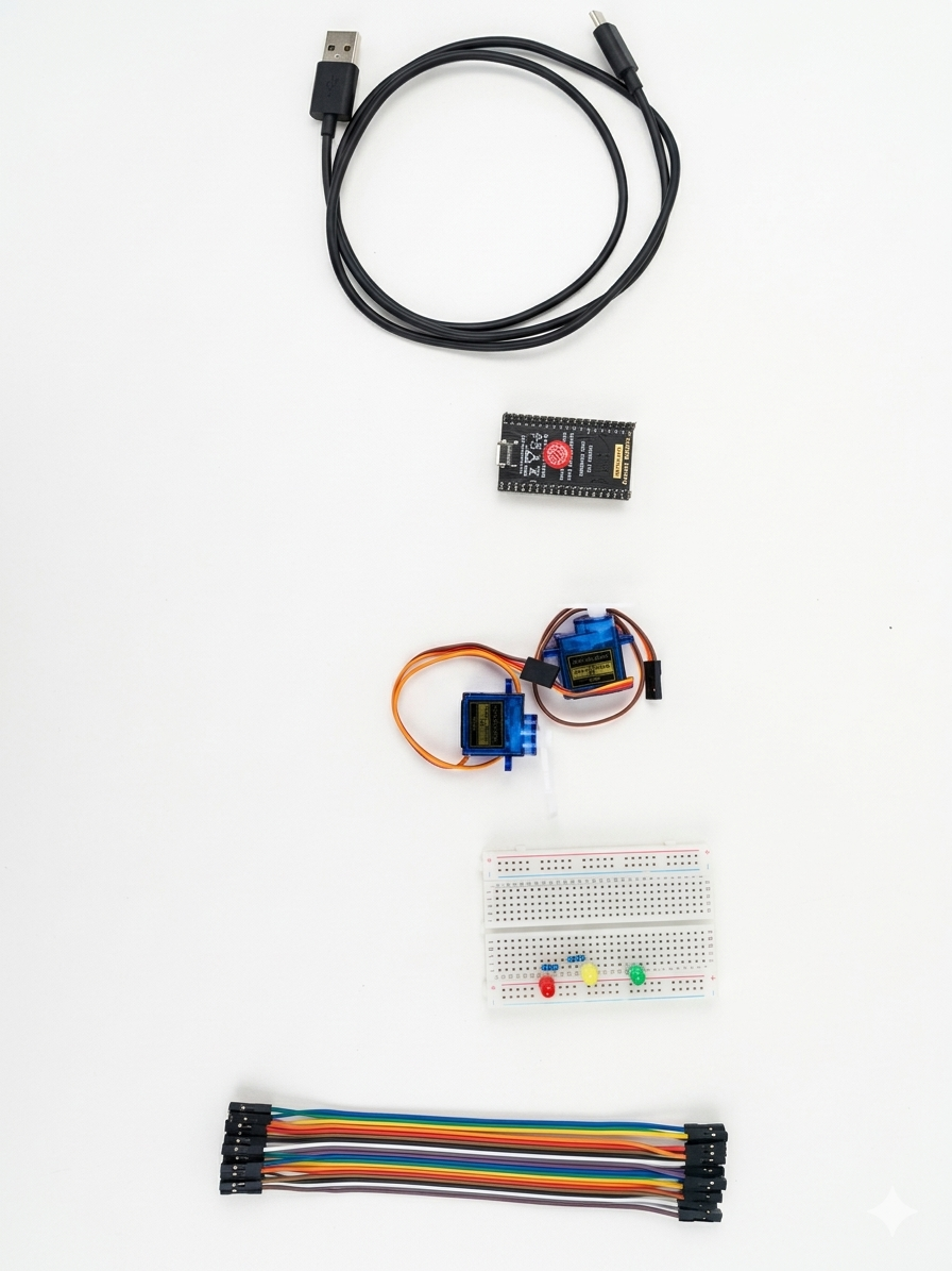
Materials
ESP32 development board
2 SG90 micro servomotors
1 red LED
1 green LED
2 resistors (220 Ω)
Breadboard
Jumper wires
USB cable
Arduino IDE
ESP32Servo library
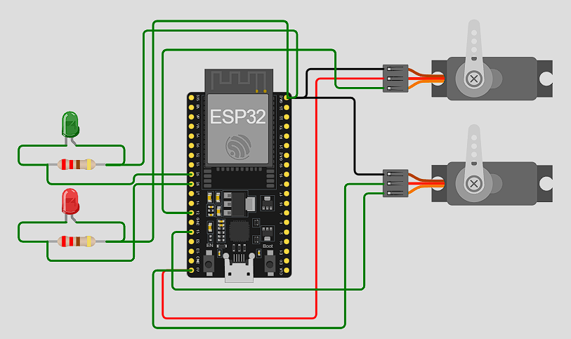
Connection Diagram
Device
ESP32 Pin
Servo Motor 1
GPIO 13
Servo Motor 2
GPIO 12
Red LED
GPIO 25
Green LED
GPIO 26
GND
GND
Servo VCC
5V
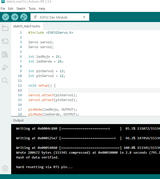
Implemented Code
					#include <ESP32Servo.h>

					Servo servo1;
					Servo servo2;

					int redLED = 25;
					int greenLED = 26;

					int servoPin1 = 13;
					int servoPin2 = 12;

					void setup() {

					servo1.attach(servoPin1);
					servo2.attach(servoPin2);

					pinMode(redLED, OUTPUT);
					pinMode(greenLED, OUTPUT);
					}

					void loop() {

					// RED LED → Motors stopped
					digitalWrite(redLED, HIGH);
					digitalWrite(greenLED, LOW);

					servo1.write(0);
					servo2.write(0);

					delay(2000);

					// GREEN LED → Motors operating
					digitalWrite(redLED, LOW);
					digitalWrite(greenLED, HIGH);

					// Servo movement sequence
					for(int i = 0; i <= 180; i++) {

						servo1.write(i);
						servo2.write(i);

						delay(8);
					}

					for(int i = 180; i >= 0; i--) {

						servo1.write(i);
						servo2.write(i);

						delay(8);
					}
					}
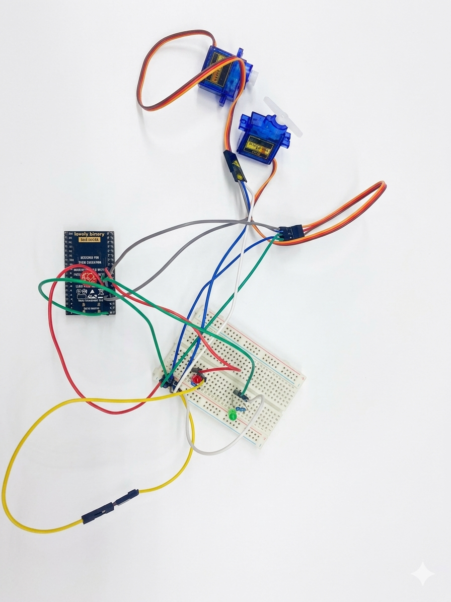
Development Process
First, the servo motors and LEDs were connected on the breadboard while carefully verifying the correct polarity and electrical connections of all components. Subsequently, the Arduino IDE development environment was configured and the ESP32Servo library was installed to enable PWM-based servo motor control.
Next, the ESP32 was programmed to execute an operational sequence. When the red LED is activated, both servomotors remain at their initial position (0°), indicating that the system is in standby mode. Afterwards, the green LED is enabled, and both servomotors perform a synchronized motion cycle from 0° to 180° before returning to the initial position, simulating an automated industrial movement process.
Finally, the system operation was verified by observing that the LEDs correctly represented the operating states while both servo motors moved synchronously according to the programmed logic.
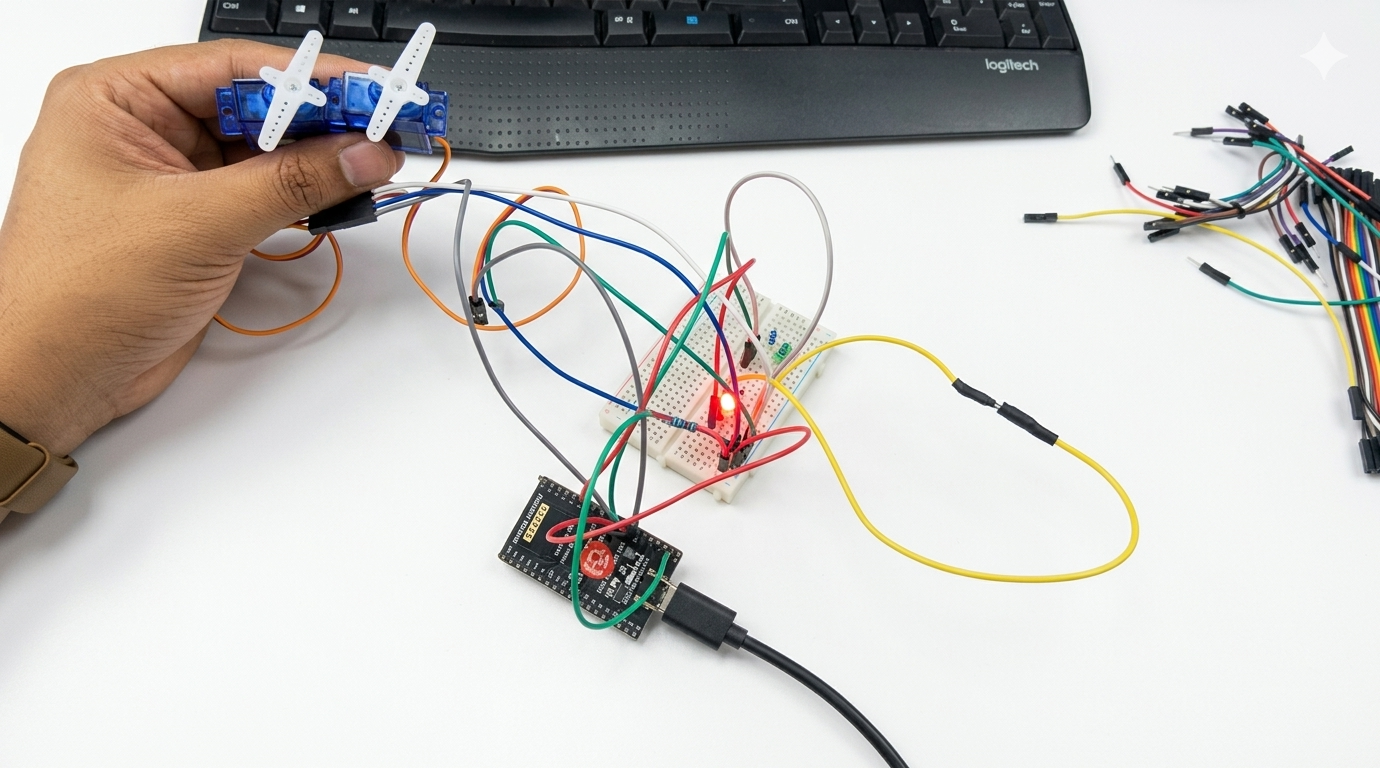
Results
Finally, we successfully implemented the simultaneous control of two SG90 servomotors using the ESP32 microcontroller. During the tests, we observed that the system responded correctly according to the programmed logic, while the LED indicators clearly represented the operational states of the system.
Additionally, we verified that both servomotors operated synchronously, allowing us to simulate real industrial automation applications such as positioning systems and controlled movement mechanisms.
Video Demonstration
Conclusions
We can conclude that the ESP32 microcontroller enables efficient control of multiple actuators through embedded programming techniques. Furthermore, the importance of visual signaling systems in automated processes was validated, since they provide a clear indication of the operational status of the system.