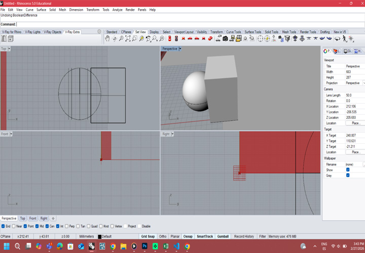
Modeling the sphere
using Rhino and Boolean Difference command
This week we will face a new challenge. In contemporary architecture, we mostly work in BIM environments, using families and real products with defined technical parameters
However, 3D modeling is more than working with predefined components. For me, it means exploring form, testing geometry, and developing ideas through digital creation.
The goal of this week will be to design a module for a modular structural wall. You will model it in 3D, explore its geometry, and prepare it for scanning and 3D printing as part of the experimental process.
See the complete group work here:

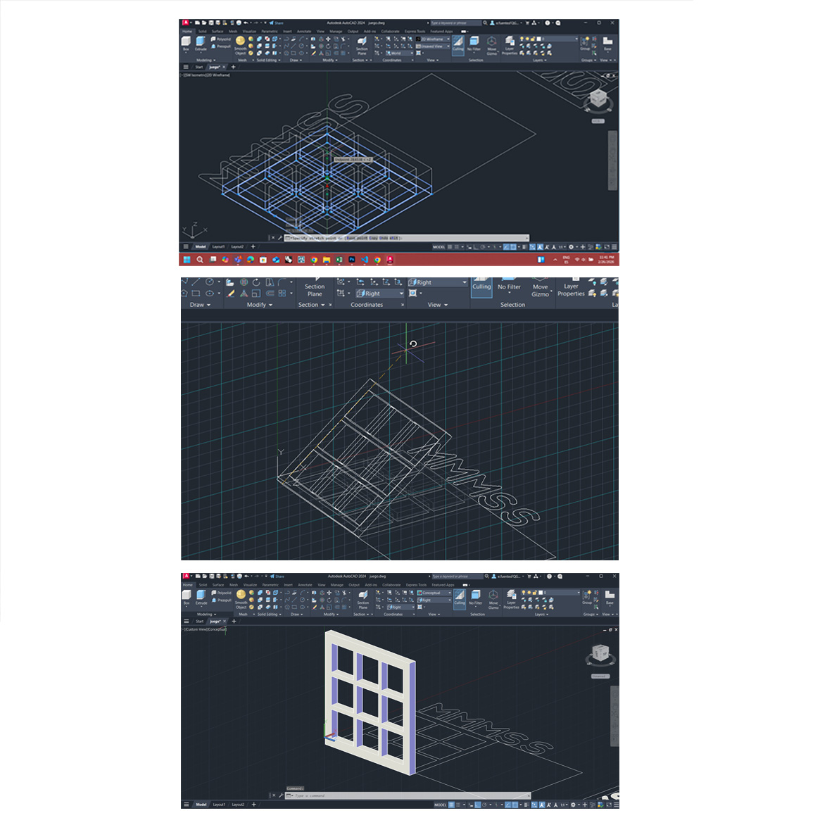
For this week’s 3D scanning and printing assignment, I started with AutoCAD 3D modeling. For me, AutoCAD will always be the easiest option when the 3D volume is simple and geometrically controlled. Since I have been working for years in technical drawing and architectural documentation, the transition from 2D plans to 3D solids feels natural.
One of the main advantages is how intuitive some tools are:
PressPull, Extrude, Revolve, Union/Subtract, FilletEdge/ChamferEdge
These commands allow me to quickly transform 2D profiles into solid volumes. The workflow is efficient, precise, and especially useful when working with orthogonal or modular geometries. Switching from 2D drafting to 3D solids is fast, and dimensions remain controlled and accurate — which is important in architecture.
However, when it comes to exploring more complex or organic forms, AutoCAD becomes less comfortable.
One of the aspects I don’t like is the interface when rotating and exploring the volume in 3D space. The navigation feels less intuitive compared to more sculptural modeling software. To properly orient the model, I constantly need:
The visible grid, The UCS (X, Y, Z axes), Orbit controls
Without clear axes and references, it becomes easy to lose orientation. Because of this, AutoCAD does not feel like the best tool for free volumetric exploration or experimental geometry. For precise, simple volumes → AutoCAD works very well. For spatial exploration and complex morphologies → it may not be the ideal option.
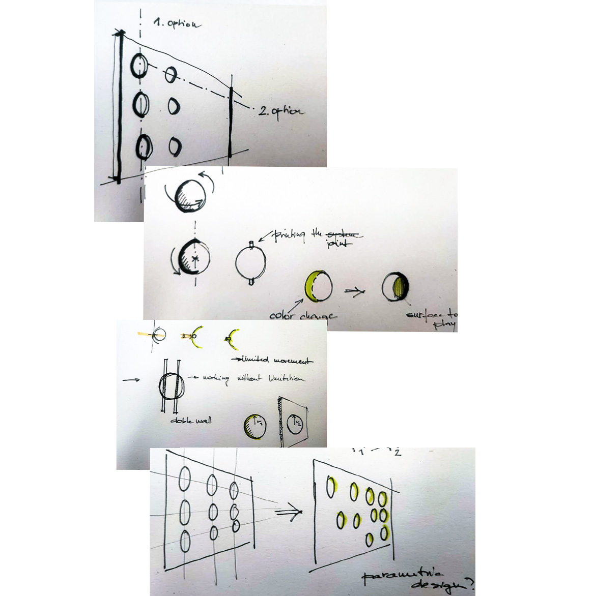
After the first 3D modeling tests, I started sketching to rethink the idea. I was developing a vertical “3 in a row” game inspired by Connect Four, but I wanted to connect it with my final project — an interactive wall.
At the beginning, the system had many holes like a traditional game board. Later, I realized I want less perforation and more solid surface. The wall should feel continuous, not empty. So I changed the idea:
This creates indirect interaction — no direct contact, but still communication through the wall. Sketching helped me simplify the system and focus on the module logic before moving to prototyping and 3D printing.
I found that modifying existing elements in the template was manageable, but writing new lines of code from scratch required more effort. This experience reinforced why choosing an organized template was so crucial—it provided a solid framework to build upon while I familiarized myself with HTML/CSS syntax.
The volume of the cut sphere was modeled in Rhino using the Sphere tool to generate the base geometry and the Boolean Difference command to subtract volumes and obtain the desired form. The wall surface, where the repetition of the spheres will be applied, was start modeling in Grasshopper. Using parametric design will allow us to control the position, spacing, and distribution of the spherical modules efficiently and flexibly for THE FINAL PROJECT.
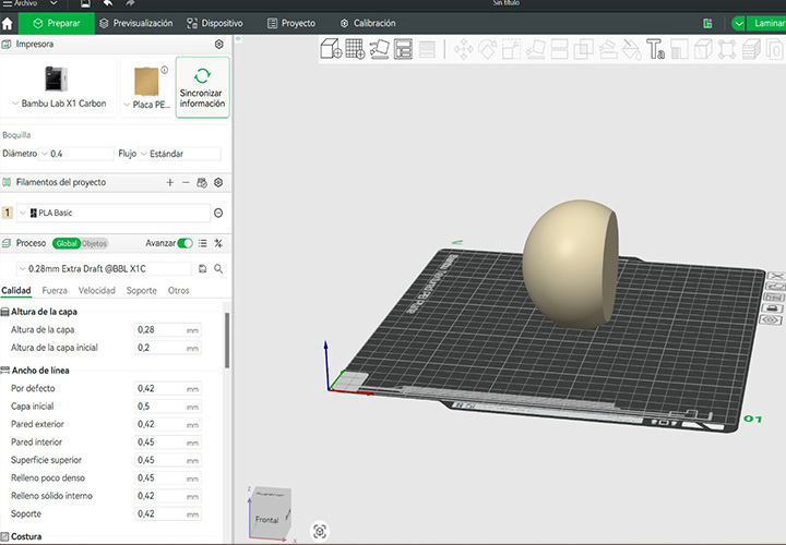
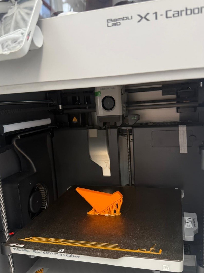
Once the digital model was completed, we exported the file and prepared it for fabrication. We opened the file in Bambu Studio to configure the printing parameters. The design was positioned on the print bed in a way that minimized the need for supports, optimizing both material use and print quality.
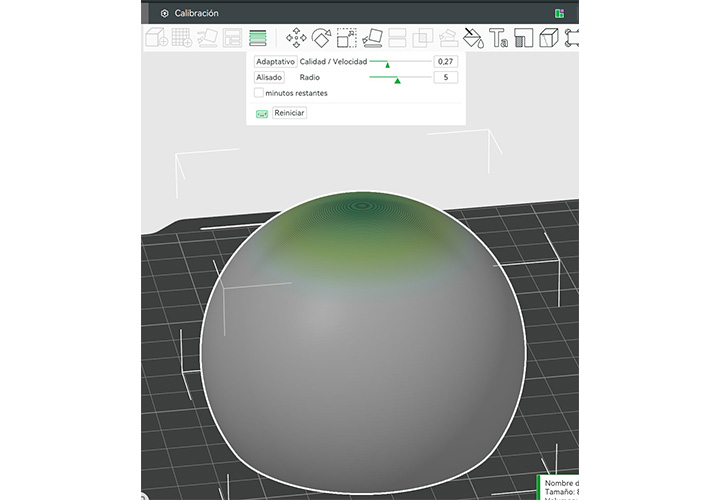
We selected a variable layer height to achieve a good surface finish while keeping the printing time reasonable. Then, we chose the available printer, build plate, and material. Since the element is not intended to withstand significant structural loads, we selected a low infill percentage to reduce material consumption and printing time.
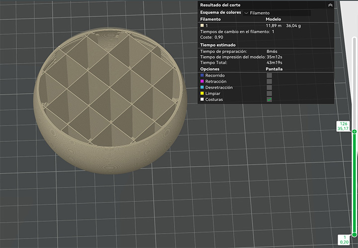
After slicing the model, we reviewed the estimated printing time and material usage. Finally, the file was sent to the 3D printer, and we monitored the process until the print was completed. This workflow allowed us to integrate parametric design and digital fabrication, moving from computational modeling to a physical prototype.
using Rhino and Boolean Difference command
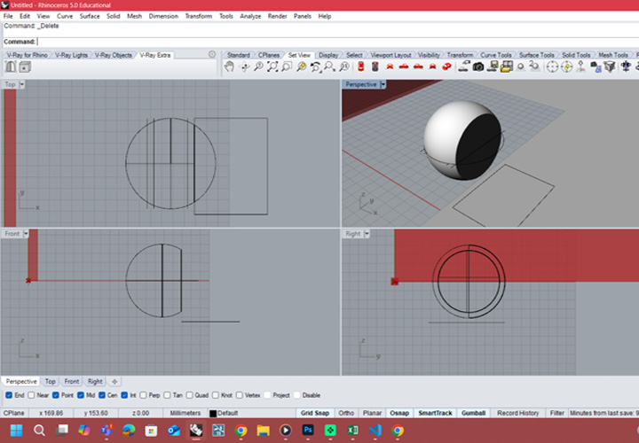
prototipe of the module for final project - sphere 8 cm
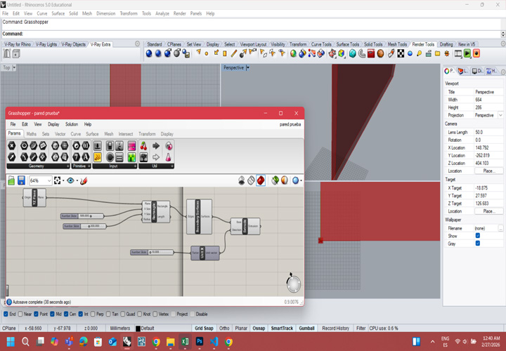
Using Grasshopper for designing the wall
exporting the file for 3D PRINTING
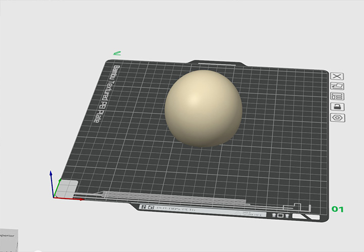
positining the model on the print bed in an specific orientation
for optimize surface quality while maintaining an efficient printing time
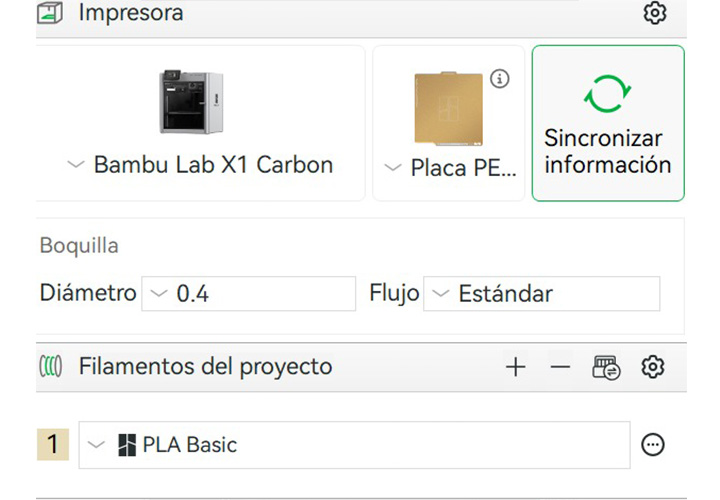
corresponding build plate configuration, and loaded material
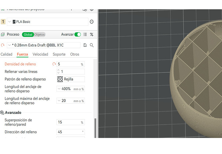
low infill density was selected
 />
/>
to preview the estimated printing time and material consumption

Sending the prototipe to the printer

waintng for te result
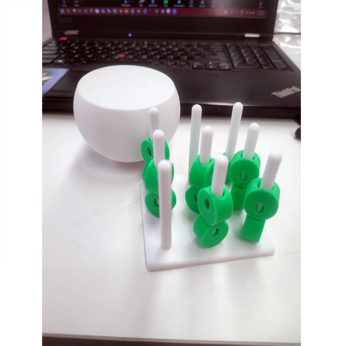
Additionally, driven by further interest in experimentation and validation of the printing process, we proceeded to fabricate an additional model based on a three-in-a-row game logic adapted to a three-dimensional configuration. This secondary model was obtained from an online open-source repository and was not developed as part of our original parametric design workflow.
The purpose of this print was primarily technical and exploratory. It allowed us to continue refining the additive manufacturing workflow, including file preparation, slicing configuration, and printer calibration verification. By working with a pre-designed model, we were able to focus specifically on optimizing print settings rather than geometry development.
Moreover, this iteration served as an opportunity to test different filament colors available in the laboratory. We evaluated color contrast, layer adhesion, and surface finish variations between materials, as well as the visual impact of multi-color combinations in modular components. This process helped us better understand material behavior, extrusion consistency, and the aesthetic potential of filament selection within small-scale functional prototypes.
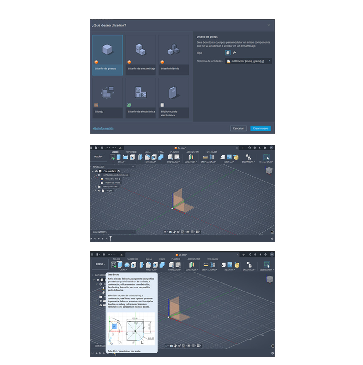
Next exercise is focused on exploring Autodesk Fusion 360. The objective was to become familiar with the interface, basic tools, and general workflow of the program. The practice involved creating simple 2D sketches and transforming them into 3D models, providing a foundational understanding of modeling concepts that can be applied in more complex design tasks.
1. Open the program and create a new design
The process begins by opening Autodesk Fusion 360 and creating a new design file. This initializes the workspace where the 3D model will be developed. At this stage, it is important to ensure that the correct units (millimeters) are selected to maintain precision.
2. Select the origin plane
The next step consists of selecting the origin plane to work on (XY, XZ, or YZ). This defines the base orientation of the model and is essential for maintaining proper alignment and proportions throughout the design process.
3. Create a sketch on the selected origin
Once the plane is selected, a new sketch is created. The sketch environment allows the definition of 2D geometry, which will later be transformed into a 3D object. This step establishes the foundation of the modeling process.
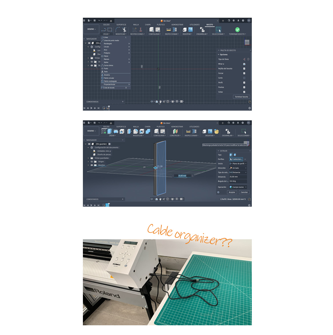
4. Draw the base geometry
Within the sketch, a rectangle or another required shape is created depending on the intended design. Dimensions are then added to define exact measurements, ensuring accuracy and parametric control of the model.
5. Finish the sketch and extrude the shape
After defining the geometry with the necessary dimensions, the sketch is completed. Using the Extrude tool, volume is added to the 2D shape by assigning a specific height. This operation transforms the sketch into a 3D solid, which serves as the base for more complex modeling operations on different planes.
In this case, a custom piece was designed for a FabLab machine to function as a cable organizer, intended to hold a cable that would otherwise remain loose or on the floor, improving workspace organization, reducing potential hazards, and protecting the cable from damage.
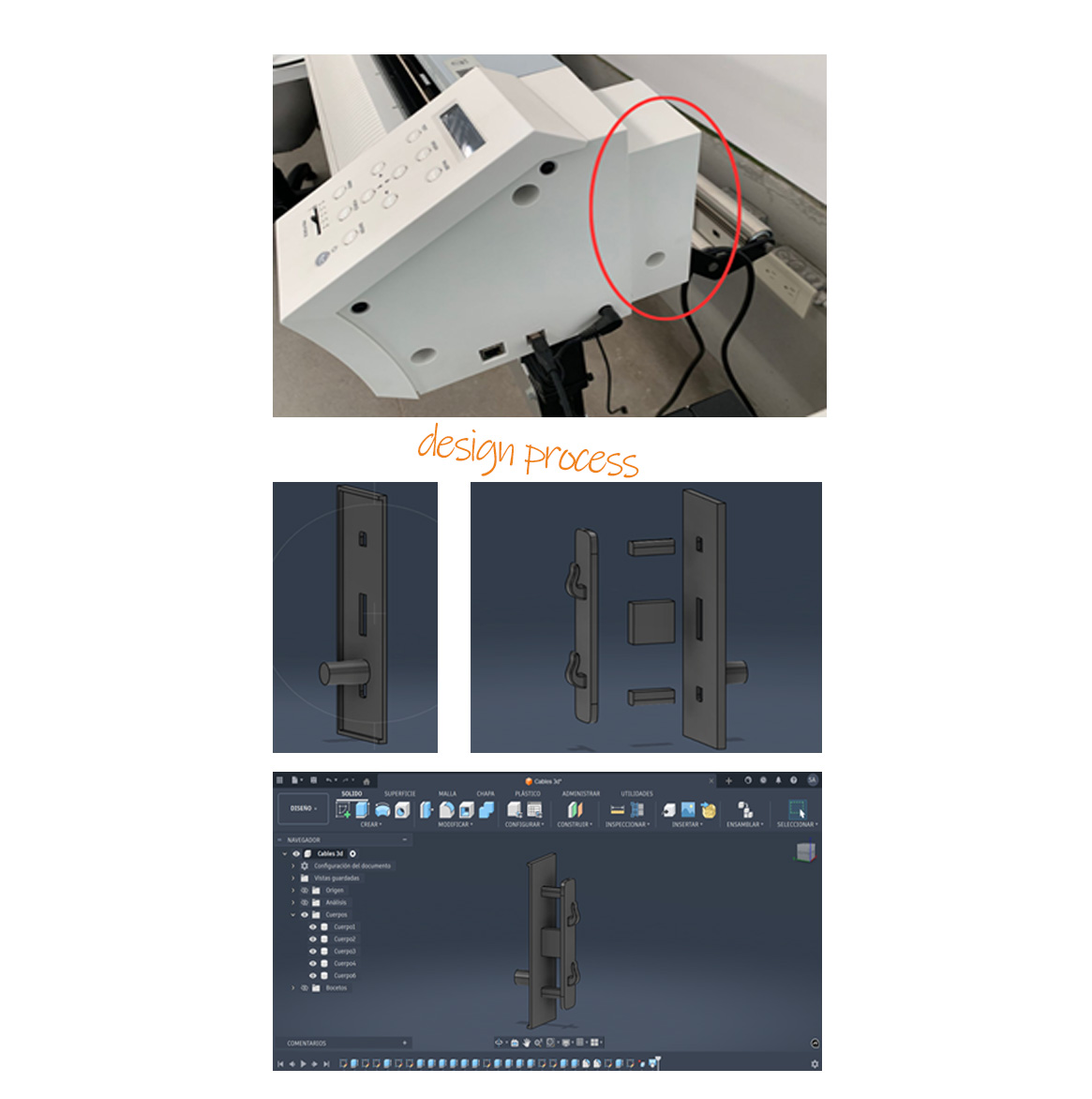
1. Measurement and Adaptation to the Machine
To begin the design process, measurements were taken directly from the machine in order to ensure a precise fit within the designated space. Both overall dimensions and specific details, such as moldings and contact surfaces, were considered to guarantee proper functional and structural integration of the piece.
2. Modular Design Strategy
The design was then developed by dividing it into separate parts. This approach was intended to optimize the fabrication process by reducing the need for support structures during 3D printing, resulting in material savings, shorter printing time, and improved surface quality.
3. Assembly and Final Configuration
Once the individual components are assembled, the final structure can be visualized as a complete system that meets the initial requirements, demonstrating an efficient modular design that facilitates assembly, as well as future adjustments or maintenance.
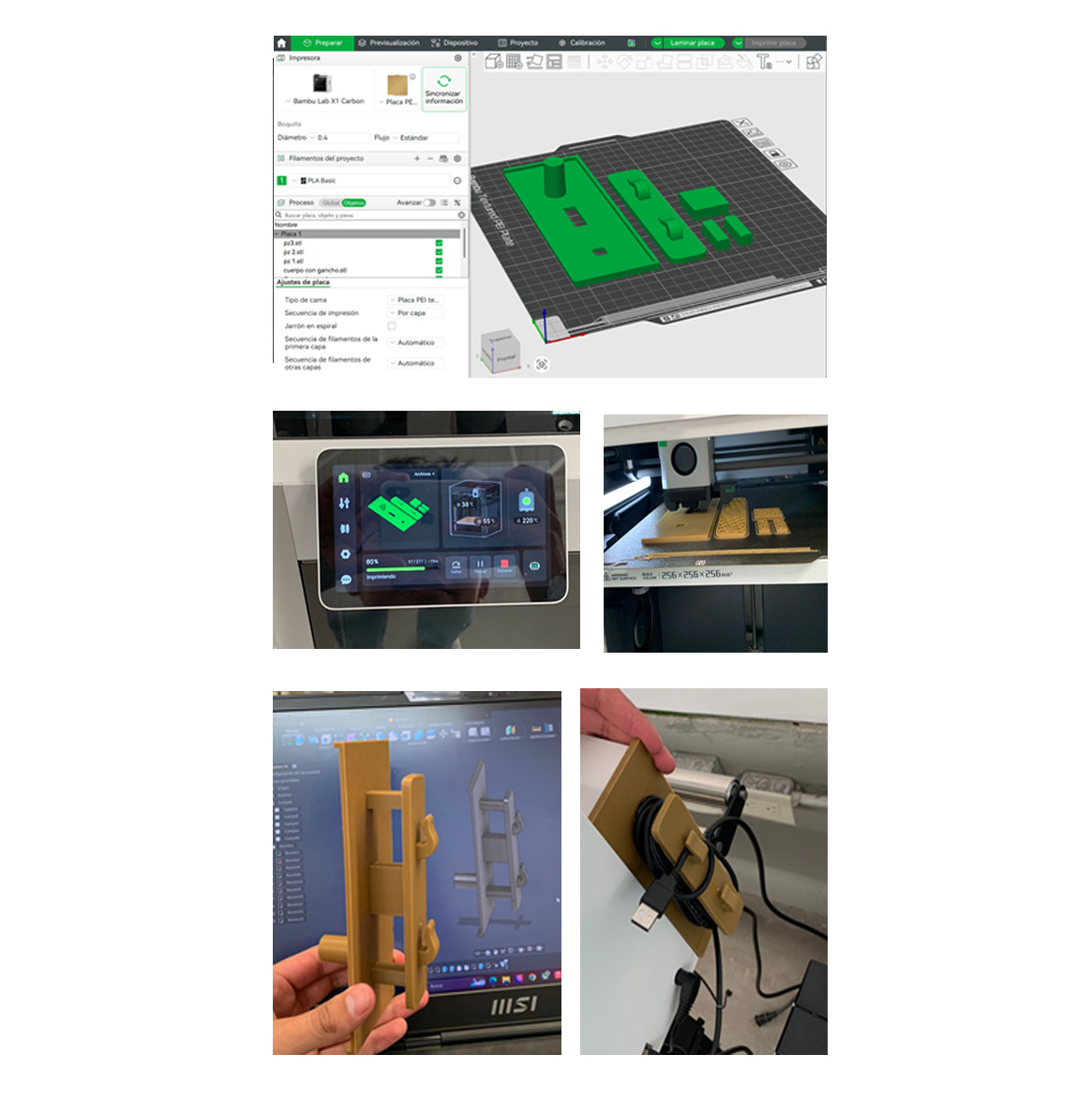
4. File Preparation in Bambu Studio
Once the design was completed, each part was imported into Bambu Studio individually and arranged side by side on the build plate. This organization ensured an efficient use of space and a controlled printing layout.
5. Slicing and Parameter Configuration
After positioning the parts, the model was sliced and the appropriate printing parameters were configured. Settings such as layer height, infill, and supports were adjusted to achieve optimal print quality and performance.
6. 3D Printing Process
The file was then sent to the 3D printer, where the printing process could be observed, allowing for monitoring and verification of correct material deposition and print stability.
7. Final Printed Result
Once the printing process was completed, the physical parts were obtained, showing the final geometry and confirming the accuracy of the design.
8. Assembly and Functional Use
Finally, the parts were assembled and placed in use, integrating the cable as intended. This demonstrated the functionality of the piece and its correct adaptation to the machine.
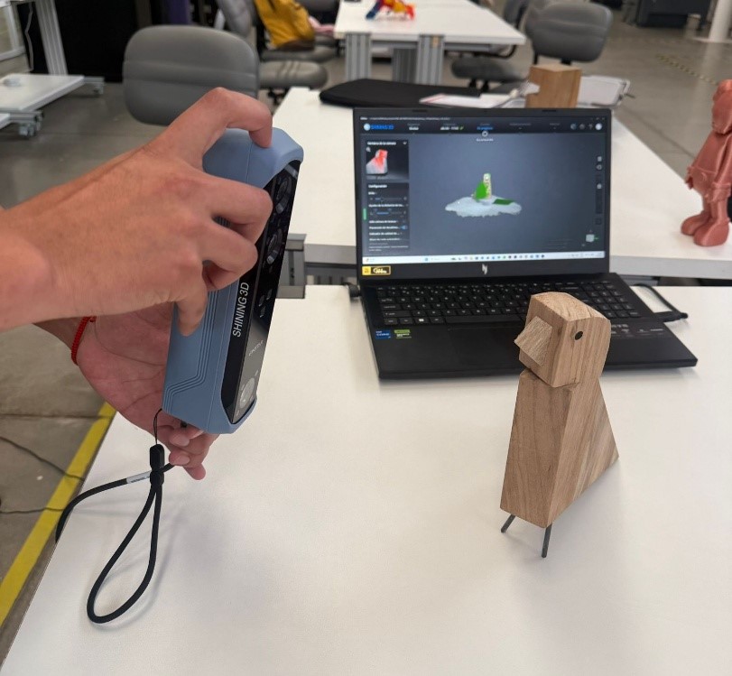
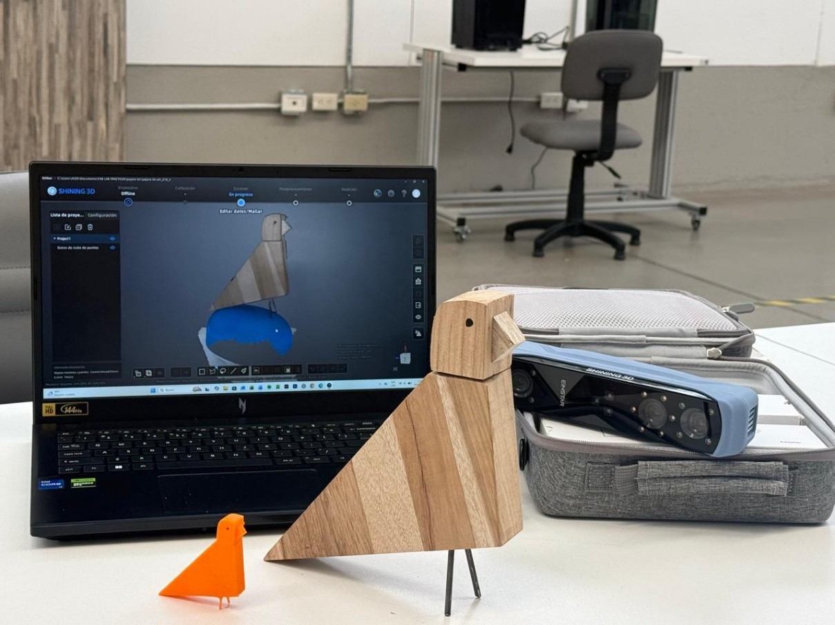
During this week at Fab Academy, we learned the complete workflow for 3D scanning and additive manufacturing using the Shining 3D EINSTAR scanner and Bambu Lab technologies. The assignment allowed us to understand the relationship between digital capture, mesh processing, and physical fabrication through 3D printing.
The objective of this exercise was to digitally scan a physical object, process the geometry into a printable mesh, and fabricate a physical replica using additive manufacturing techniques.
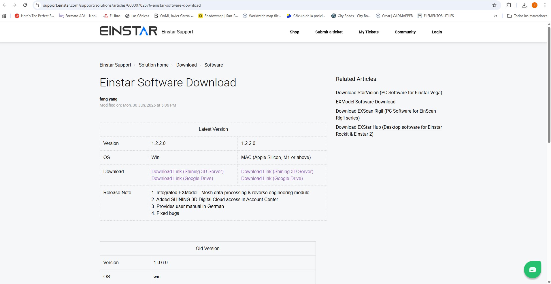
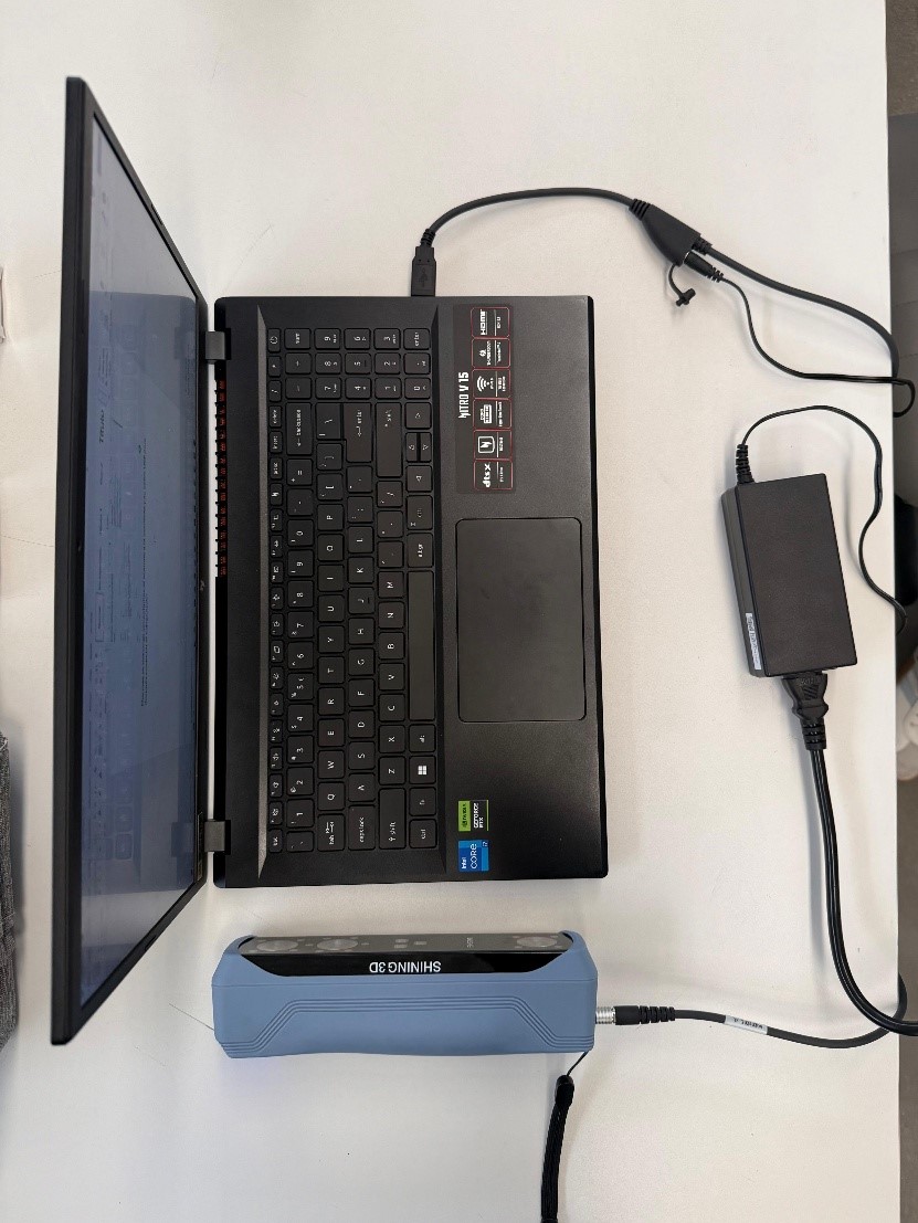
To begin the process, we downloaded and installed the official EINSTAR software from the support website. While the software was downloading, we connected the scanner to the power supply and linked it to the computer using the USB connection cable.
After connecting the scanner to the workstation, we launched the EINSTAR application and logged into the platform.
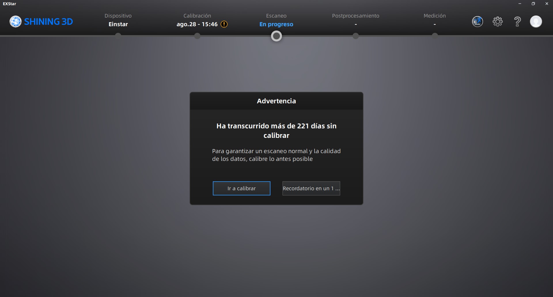
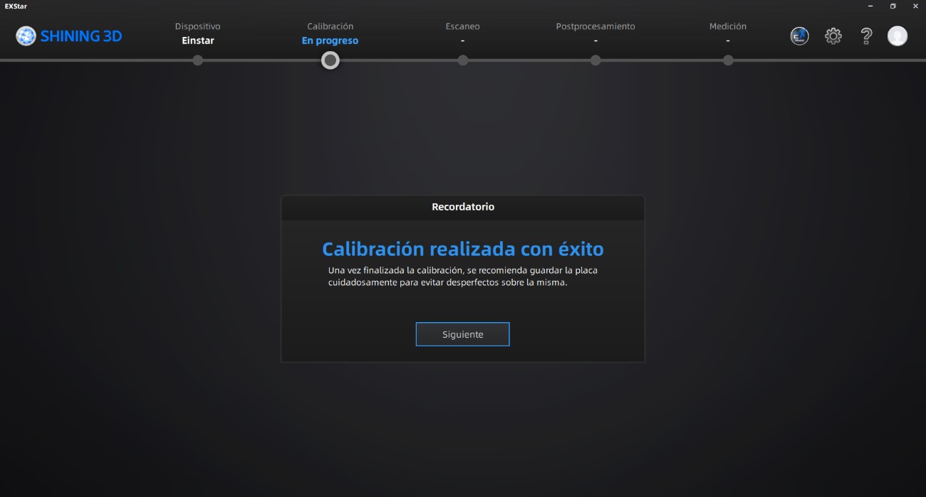
Before starting the scanning workflow, it was necessary to calibrate the scanner to ensure accurate geometry acquisition and proper depth detection.
We followed all calibration instructions displayed by the software interface, carefully rotating and positioning the calibration board according to the required directions.
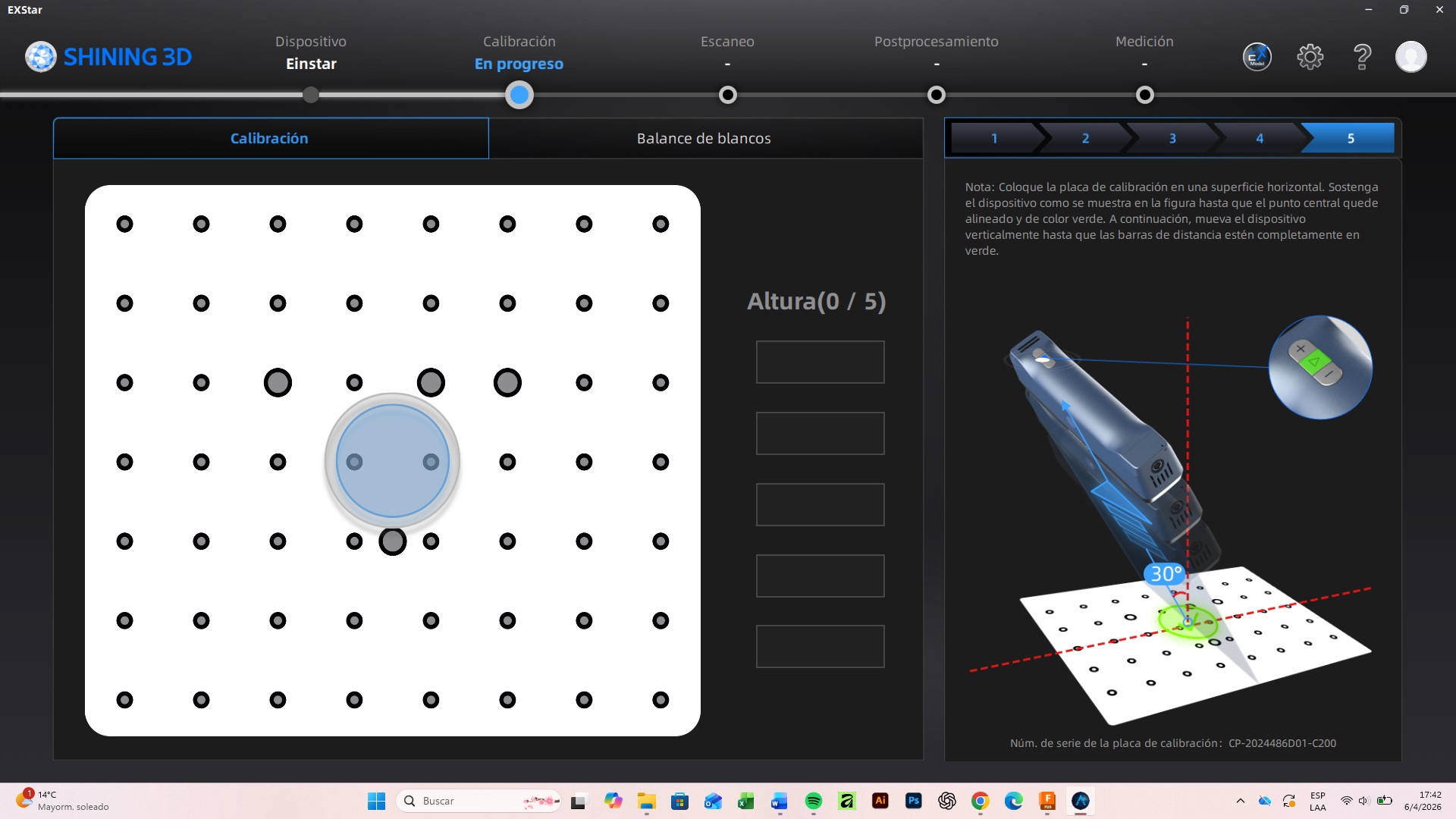
After completing the first calibration stage, the software confirmed successful alignment and calibration.
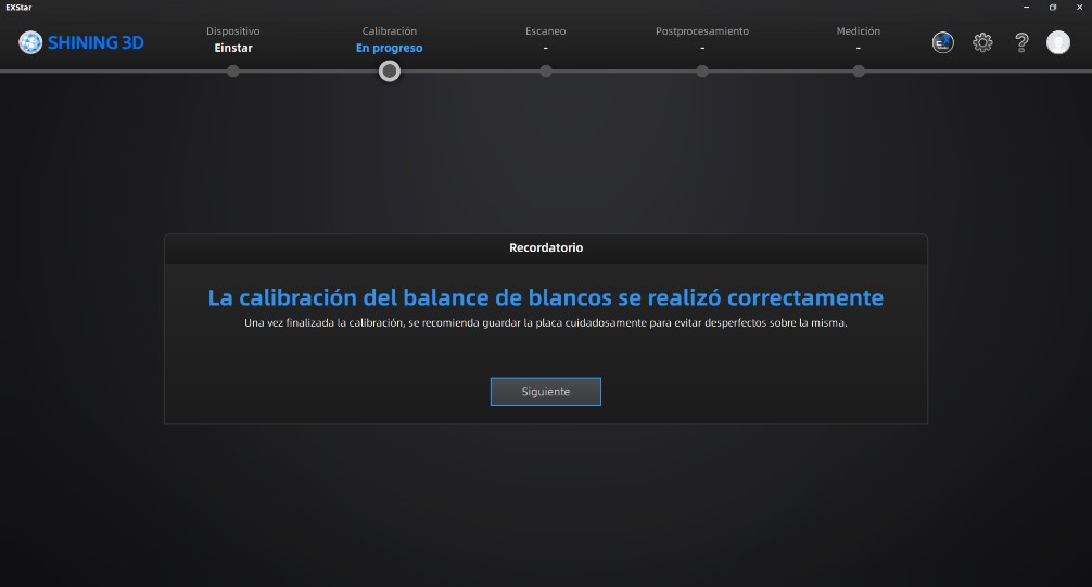
Subsequently, we performed the white balance calibration process following all the required steps to optimize color and lighting recognition during the scan.
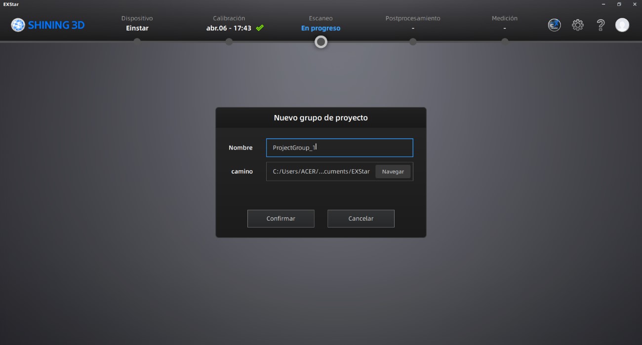
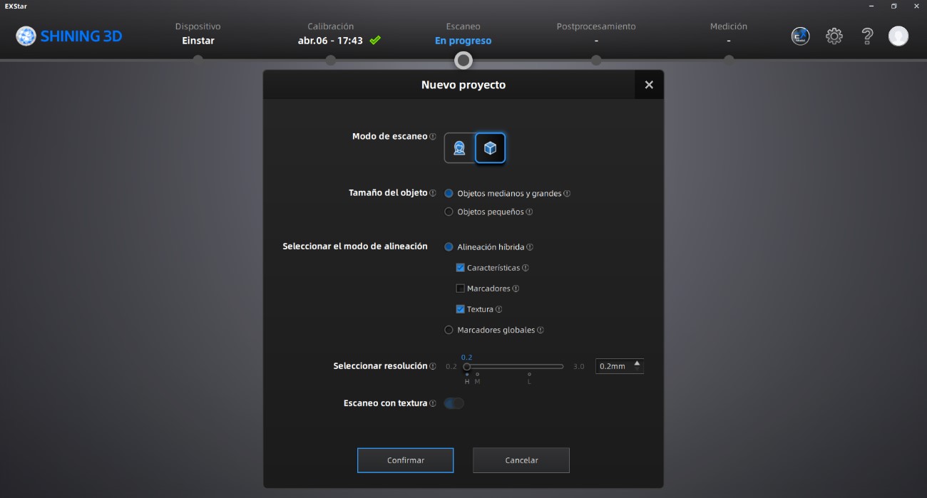
Once the scanner calibration was completed, we created a new project group, assigning a project name and selecting a storage location for all generated files.
The object selected for this exercise was a small wooden bird sculpture. Before starting the scan, we configured the scanning parameters according to the object scale and required detail level.
Initially, we tested a scanning resolution of 0.5 mm, but the captured geometry lacked sufficient detail.
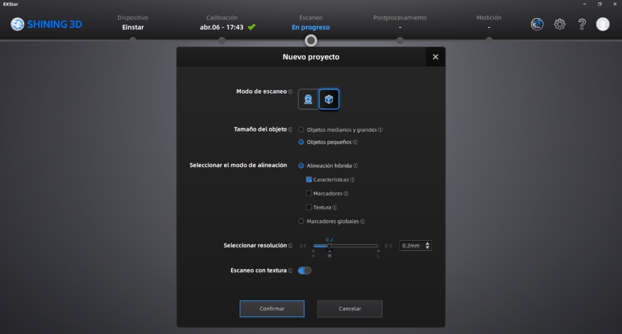
To improve geometric precision and surface definition, we changed the resolution setting to 0.2 mm.
After configuring the project, we started the scanner preview mode by pressing the play button. During this stage, we adjusted brightness levels, object positioning, and environmental lighting conditions to optimize scan quality.
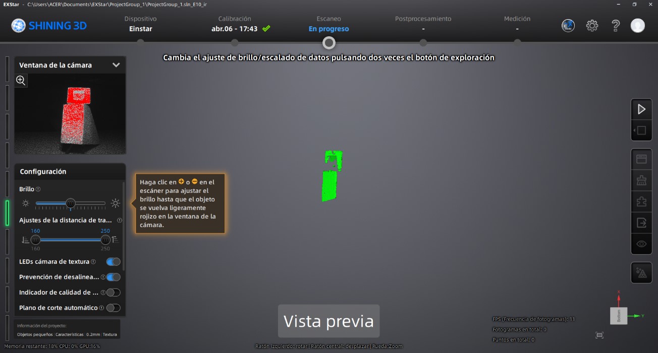
Once the preview settings were validated, we initiated the scanning process and continuously moved around the object to ensure complete surface coverage.
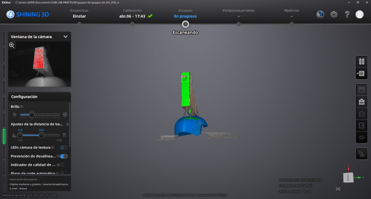
After confirming that the object had been completely captured, we paused the scanning process.
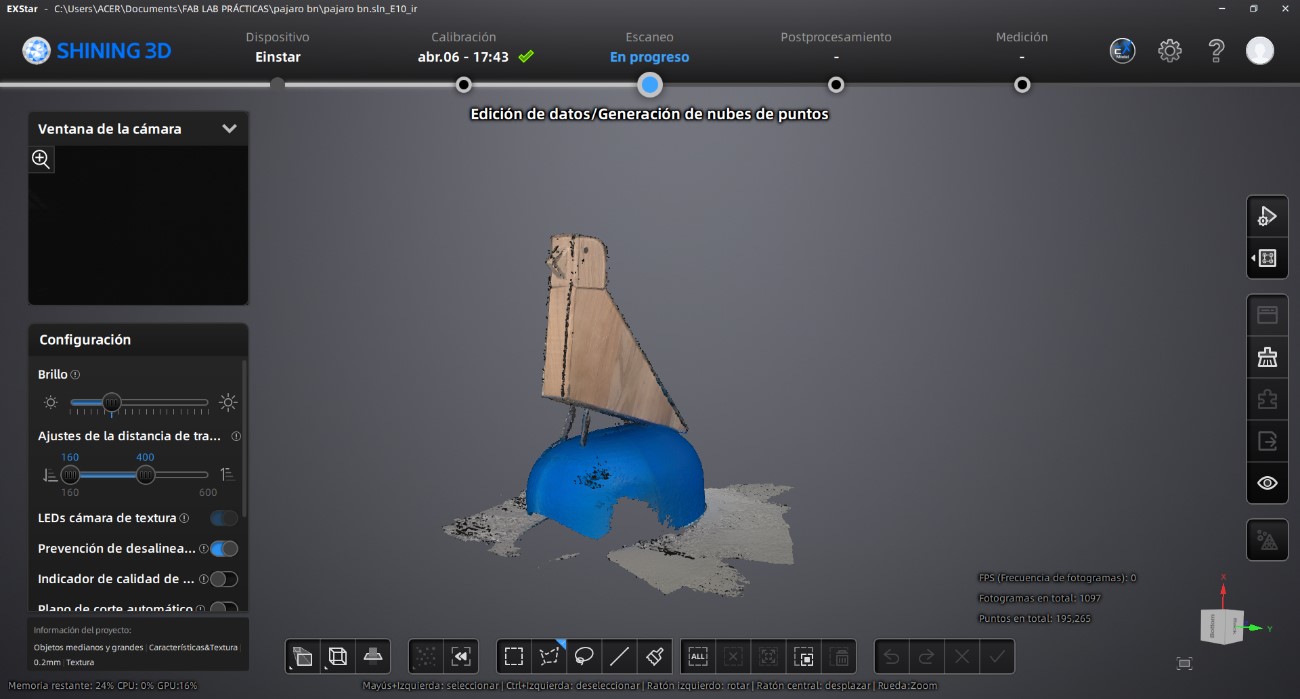
After completing the scan, we generated a point cloud using the processing tools located on the right-side panel of the software interface.
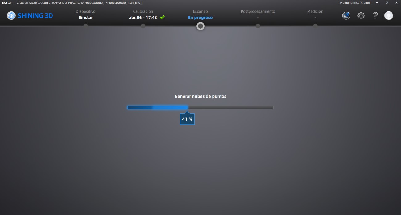
Once the point cloud generation was completed, we created a polygonal mesh from the scanned data.
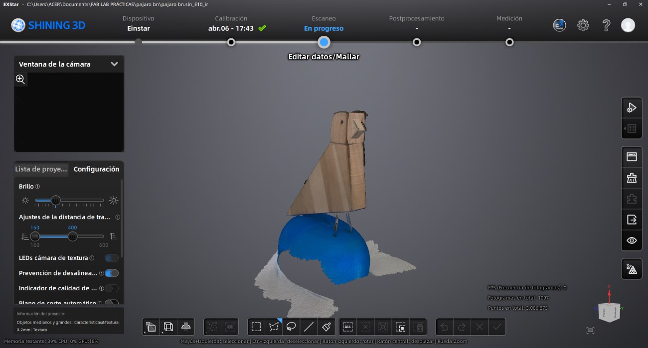
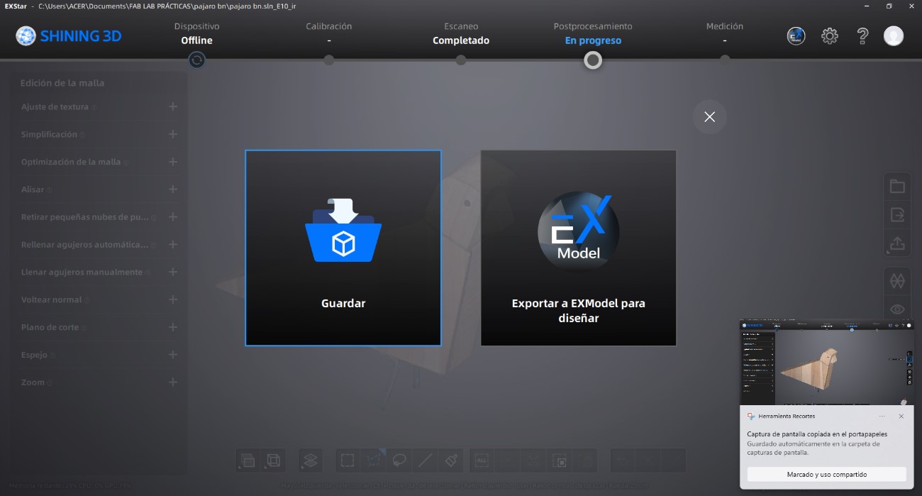
At this stage, we refined the geometry by removing unwanted surfaces and correcting mesh imperfections. In this case, we removed the scanned base and cleaned the edges of the wooden bird model using the editing tools available in the lower toolbar.
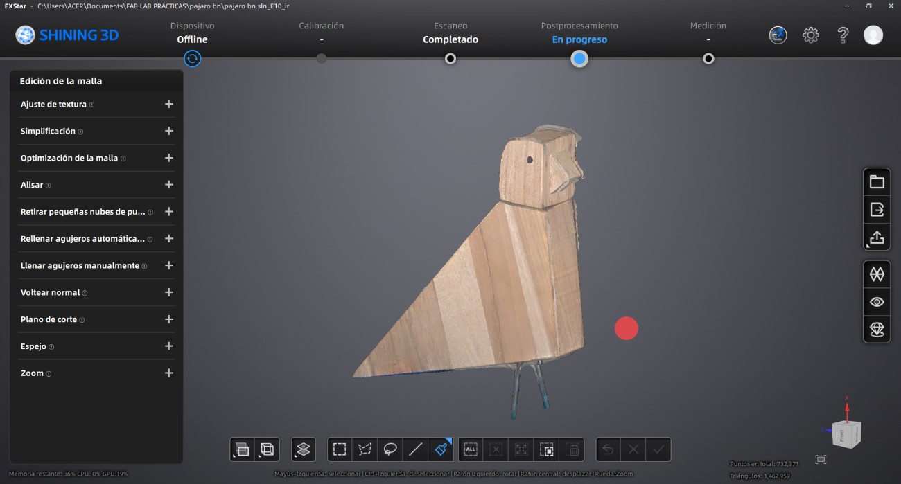
Finally, the processed model was exported in compatible 3D printing formats such as OBJ and STL.
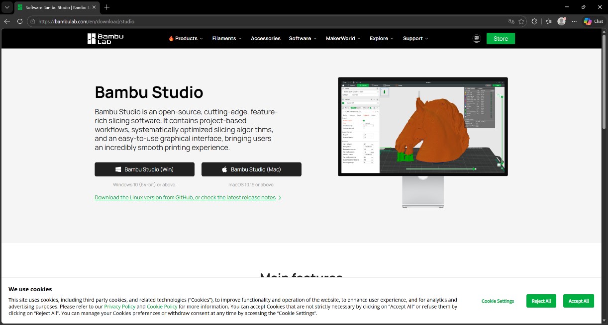
To prepare the model for fabrication, we downloaded and installed Bambu Studio. After opening the software, we selected the corresponding printer model and configured the build plate dimensions.
From the “Prepare” workspace, we imported the previously exported STL file.
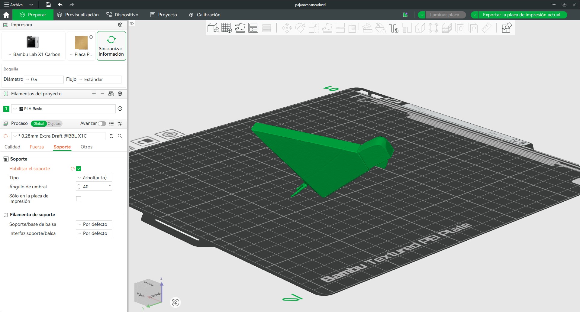
Once the model was imported, we adjusted its orientation to optimize stability and support generation during printing. To validate the slicing configuration, we generated the toolpath preview by slicing the plate.
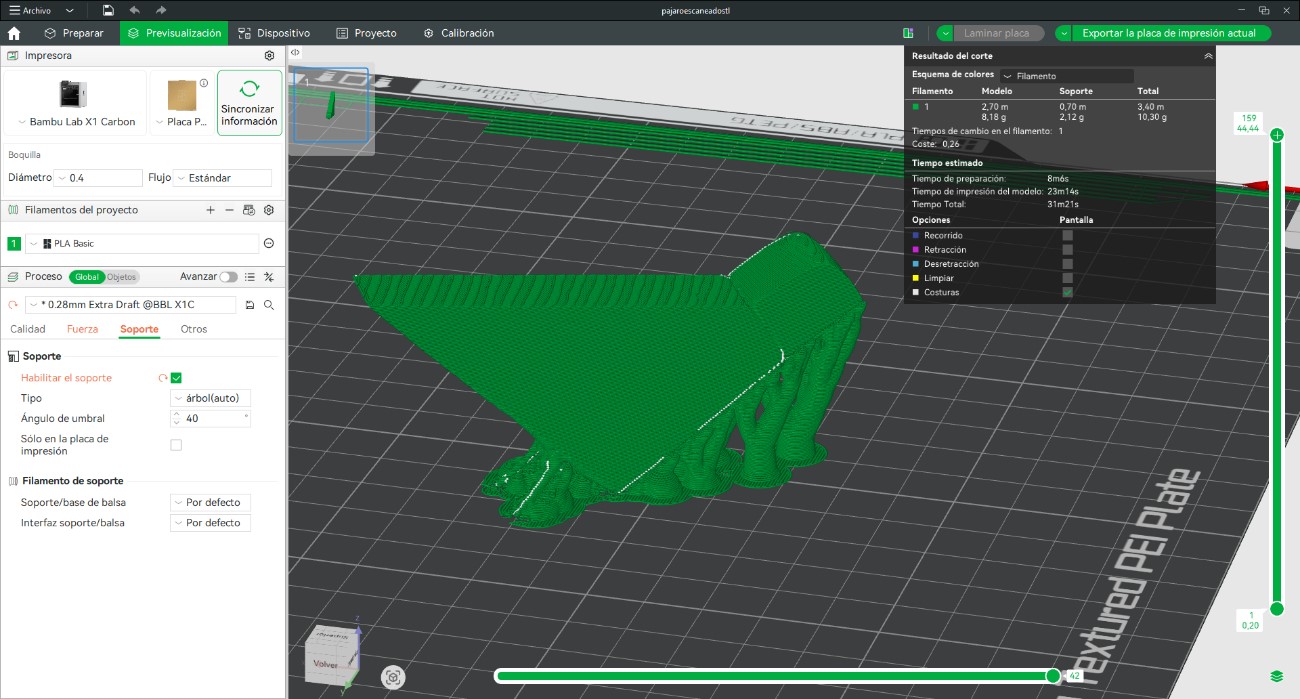
After confirming the slicing parameters, we started the printing process. Once fabrication was completed, we removed the support structures and cleaned the final object.
The final printed model was then compared with the original scanned object to evaluate geometric accuracy and reproduction quality.
Throughout this week, we explored different workflows related to 3D modeling, parametric design, digital fabrication, and 3D scanning technologies. The exercises allowed us to move from conceptual exploration to physical prototyping, integrating both technical precision and experimental design methodologies.
Using AutoCAD, we developed controlled volumetric geometries through solid modeling operations such as Extrude, PressPull, Revolve, and Boolean commands. This process reinforced the advantages of CAD environments for modular and orthogonal architectural systems where dimensional accuracy is essential.
At the same time, sketching became an important design tool to rethink interaction and spatial logic within the modular wall system connected to the final project. Through iterative sketches, the concept evolved from a perforated game board into a rotating modular system that promotes indirect interaction between users through movement, color, and spatial communication.
The parametric modeling workflow developed in Rhino and Grasshopper allowed us to explore repetition, modularity, and surface organization computationally. Using Boolean Difference operations and parametric control systems, we generated adaptable geometries capable of evolving into larger interactive wall configurations for future development.
The fabrication stage successfully translated the digital models into physical prototypes through additive manufacturing. By configuring slicing parameters in Bambu Studio, minimizing supports, selecting variable layer heights, and optimizing infill density, we achieved efficient prints with acceptable surface quality and reduced material consumption.
Additionally, the custom cable organizer project demonstrated the practical application of digital fabrication for solving real workshop needs. The modular strategy improved assembly efficiency and reduced fabrication complexity while validating dimensional precision and functional adaptation to the machine.
Finally, the 3D scanning workflow using the EINSTAR scanner allowed us to understand the complete process of digital capture, point cloud generation, mesh optimization, and physical reproduction through 3D printing. The final scanned and printed object accurately reproduced the geometry of the original wooden sculpture, validating the effectiveness of the scanning resolution and mesh processing workflow.
This week provided a comprehensive understanding of the relationship between digital modeling, parametric design, 3D scanning, and additive manufacturing within contemporary digital fabrication workflows. Beyond simply producing physical objects, the assignment demonstrated how computational tools can support experimentation, iteration, and the translation of conceptual ideas into tangible prototypes.
We learned that different software environments respond to different design intentions. AutoCAD proved efficient for precise and controlled geometries, while Rhino and Grasshopper offered greater flexibility for parametric exploration and modular systems. Fusion 360 introduced a more integrated workflow between sketching, modeling, and fabrication-oriented design.
The fabrication process also highlighted the importance of understanding material behavior, print orientation, support reduction, layer configuration, and infill optimization. These variables directly influence print quality, fabrication time, and material efficiency.
Furthermore, the integration of 3D scanning technologies expanded our understanding of reverse engineering and digital reproduction processes. Calibrating the scanner, generating point clouds, refining meshes, and preparing files for fabrication revealed how physical objects can be transformed into editable digital assets with high geometric fidelity.
Overall, this week strengthened our technical and conceptual understanding of digital fabrication processes while reinforcing the importance of experimentation, iteration, and prototyping as part of architectural and computational design practice.