Arduino Nano Datasheet Analysis

The pinout is one of the most important parts of the datasheet, as it shows the distribution of digital, analog, and communication pins. This allows a better understanding of how to connect sensors, actuators, and external modules within an embedded system. Both the Arduino Uno and Arduino Nano offer a flexible pin configuration, making them suitable for prototyping and basic electronic applications

Key Features:

  • 14 digital pins (D0–D13): Used for input and output operations.
  • 6 analog pins (A0–A5): Allow reading variable signals.
  • 6 PWM pins: Enable control of motors and LEDs.
  • Communication protocols: UART, SPI, I2C.
  • Power pins: 5V, 3.3V, GND.
  • Important Pin Configuration

    The pin configuration defines how the board interacts with external components and is essential for circuit design and system integration.

    • Digital pins: D0–D13, used for input and output operations with digital components.
    • Analog pins: A0–A5, allow reading variable signals from sensors.
    • Communication: UART, SPI, I2C, enabling data exchange with other devices and modules.
    • Power supply: 5V, 3.3V, and GND for powering external components.

    Technical Specifications

    This section describes the capabilities of the microcontroller and its hardware limitations, which are important when defining the scope of a project.

    • Microcontroller: ATmega328P, the main processing unit of the board.
    • Clock speed: 16 MHz, which determines the execution speed of instructions.
    • Flash memory: 32 KB, used to store the program code.
    • SRAM: 2 KB, used for temporary data during program execution.
    • EEPROM: 1 KB, for storing non-volatile data.
    • Operating voltage: 5V, required for stable operation.

    Main Board Components

    The datasheet also identifies the main physical components of the Arduino Uno, which are necessary for its functionality and programming.

    • ATmega328P microcontroller: Executes the program and controls all operations.
    • USB port: Used for programming and power supply.
    • Voltage regulator: Ensures a stable voltage supply to the board.
    • 16 MHz crystal oscillator: Provides the timing signal for the microcontroller.
    • Reset button: Allows restarting the program when needed.

    Practical Development

    Control of an SG90 Micro Servo Using a Potentiometer with Arduino

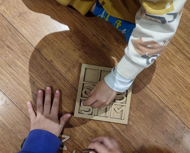
    An embedded system was developed using an Arduino Uno to control the position of an SG90 micro servo through a potentiometer. The system allows the servo angle to vary between 0° and 180°, depending on the position of the potentiometer, providing a simple and intuitive way to control motion.

    In this setup, the potentiometer acts as an input device by generating a variable voltage signal. The Arduino reads and processes this analog signal, mapping it into a corresponding angle value. Finally, the servo motor operates as the output device, adjusting its position according to the processed signal.

    Materials Used

    • Arduino Uno: Main microcontroller used for processing and control.
    • SG90 Micro Servo (9g): Actuator responsible for angular movement.
    • 10kΩ Potentiometer: Input device used to vary the control signal.
    • Protoboard: Used for assembling the circuit without soldering.
    • Jumper wires: For electrical connections between components.
    • USB cable: Provides power and enables programming of the board.
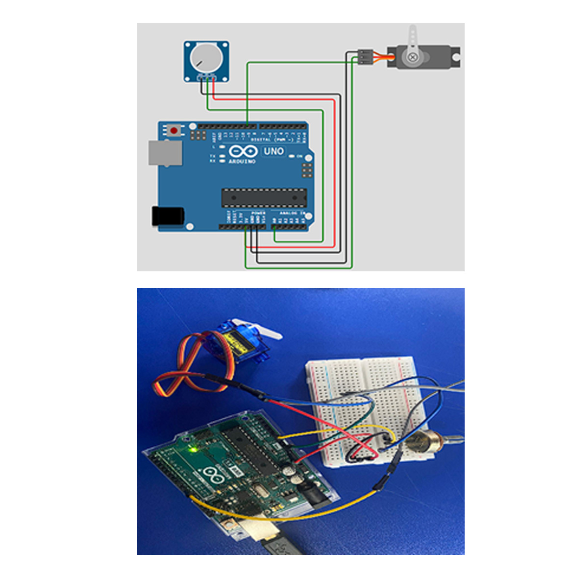
    Connection Diagram

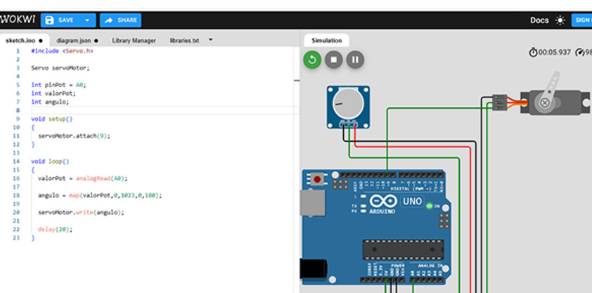
    The circuit connections and simulation were developed using Wokwi, an open-source electronic simulation platform. This tool allows the design, testing, and validation of embedded systems in a virtual environment before physical implementation, reducing errors and improving the overall development process.

    Through the simulation, it was possible to verify the correct behavior of the system, ensuring that the potentiometer input accurately controls the servo motor position.

    Procedure

    The development process began by connecting the Arduino Uno to the protoboard, creating a stable base for the circuit assembly. All ground (GND) connections were then linked together to ensure a common reference and avoid potential differences that could affect system performance.

    Next, the potentiometer was connected as the input device. Its central pin (wiper) was connected to the analog pin A0 of the Arduino, allowing the board to read the variable voltage generated by the potentiometer.

    After that, the servo motor was integrated into the circuit. The signal wire was connected to digital pin 9, while the ground wire was connected to GND and the power wire to the 5V pin of the Arduino. This configuration enables the servo to receive PWM signals for position control.

    Once all connections were completed, the program was uploaded to the Arduino Uno. Finally, the system was powered through the USB port, and its functionality was verified by rotating the potentiometer and observing the corresponding movement of the servo motor.

    Implemented Code

    
    								#include <Servo.h>
    
    								Servo servoMotor;
    
    								int pinPot = A0;
    								int valorPot;
    								int angulo;
    
    								void setup() 
    								{
    								servoMotor.attach(9);
    								}
    
    								void loop() 
    								{
    								valorPot = analogRead(A0);
    								angulo = map(valorPot, 0, 1023, 0, 180);
    								servoMotor.write(angulo);
    								delay(20);
    								}
    								

    System Operation

    The system operates through a simple input-process-output logic, where each component plays a specific role within the embedded system.

    • Input: The potentiometer generates an analog signal that varies according to its position.
    • Processing: The Arduino Uno reads the analog value and converts it into a corresponding angle using PWM control.
    • Output: The SG90 servo motor adjusts its angular position based on the processed signal.
    Description

    Results Obtained

    The system successfully controlled the angular position of the servo motor within a range of 0° to 180° using the potentiometer. The response was smooth and proportional to the rotation of the potentiometer, demonstrating accurate signal reading and processing.

    This result confirms the correct operation of the embedded system, as well as the effective communication between the input device (potentiometer), the processing unit (Arduino Uno), and the output device (SG90 servo motor).

    Overall, the implementation validates the integration of analog input with PWM output, highlighting the reliability and functionality of the system for basic motion control applications.