01
Drawing in AutoCAD
My final project revolves around the intimate dialogue between children and microarchitecture: the idea that a structure can be a playmate rather than just a container. To begin this journey, I’ve scaled down the complexity but kept the soul of the interaction intact through a laser-cut "Three-in-a-Row" (Tic-Tac-Toe) game. I chose this game because it is my children’s favorite; it is a catalyst for quick, direct communication. However, to transform a generic toy into a piece of personalized micro-space, I replaced the traditional "X" and "O" with the letters "M" and "S"—the initials of their names. By using their names, the game ceases to be an abstract puzzle and becomes a reflection of their identity.
See the complete laser cutter characterization and group documentation here:

This game serves as the first heartbeat of my project. It transitions from a simple "human-to-human" match into a "human-to-object" experience.
The Tactile Language: By using the laser cutter to create precise, interlocking pieces, I am exploring how children’s hands interpret geometry. The way a piece fits into its slot is not only a mechanical action, but also a sensory satisfaction that connects the child to the physical craft.
Micro-Spaces of Interaction: Even in this small format, the game acts as a micro-architecture for two players. It defines a boundary, creates a shared focal point, and invites children to manipulate their environment to achieve a goal.
The Ludic Bridge: This exercise works as a proof of concept for wonder. If a simple grid can spark a moment of joy, then a full-scale micro-architectural structure can transform a child’s perception of the world.
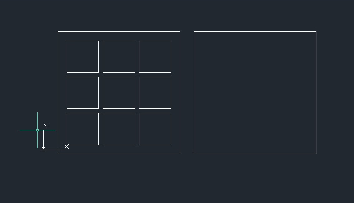
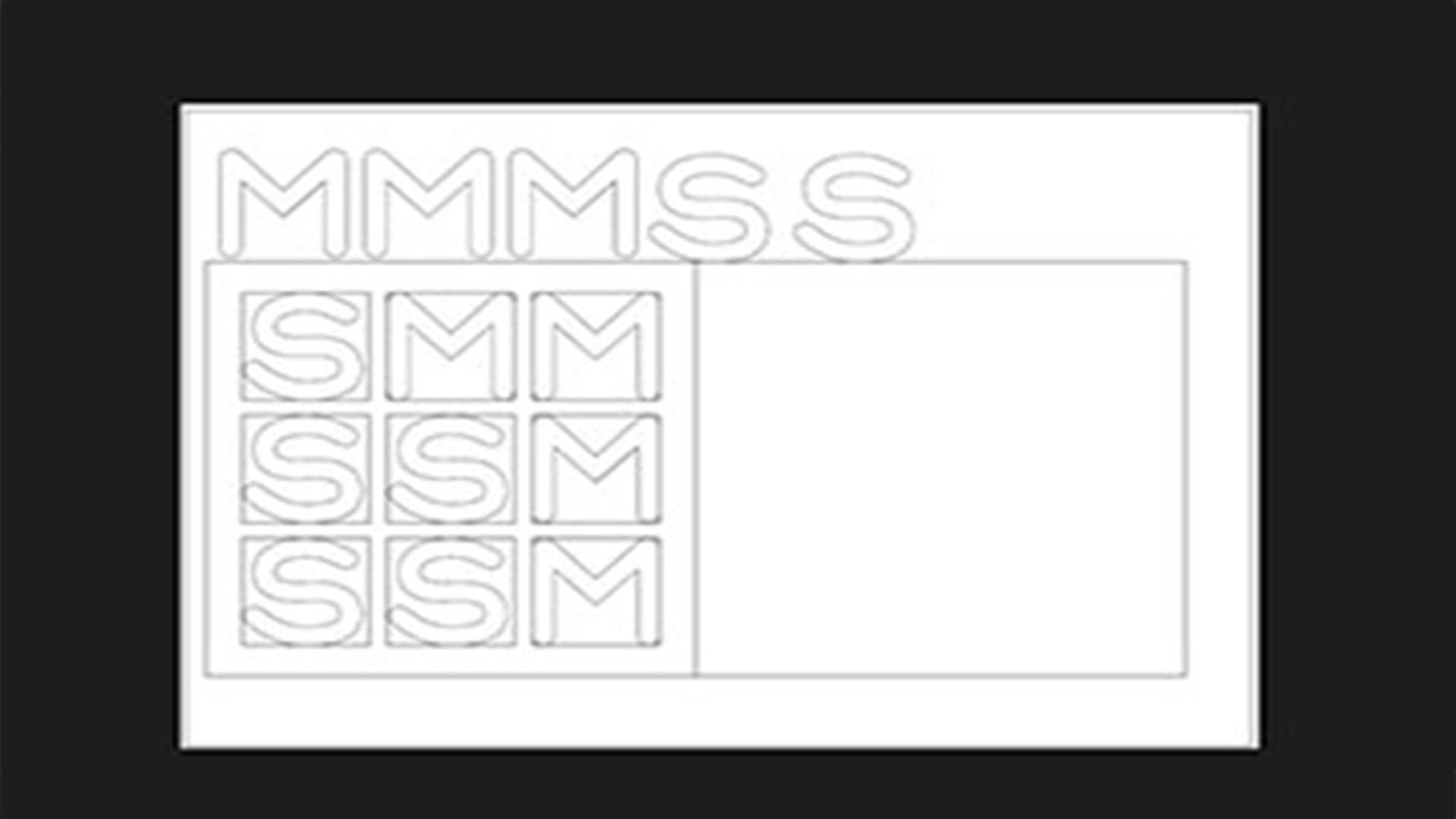
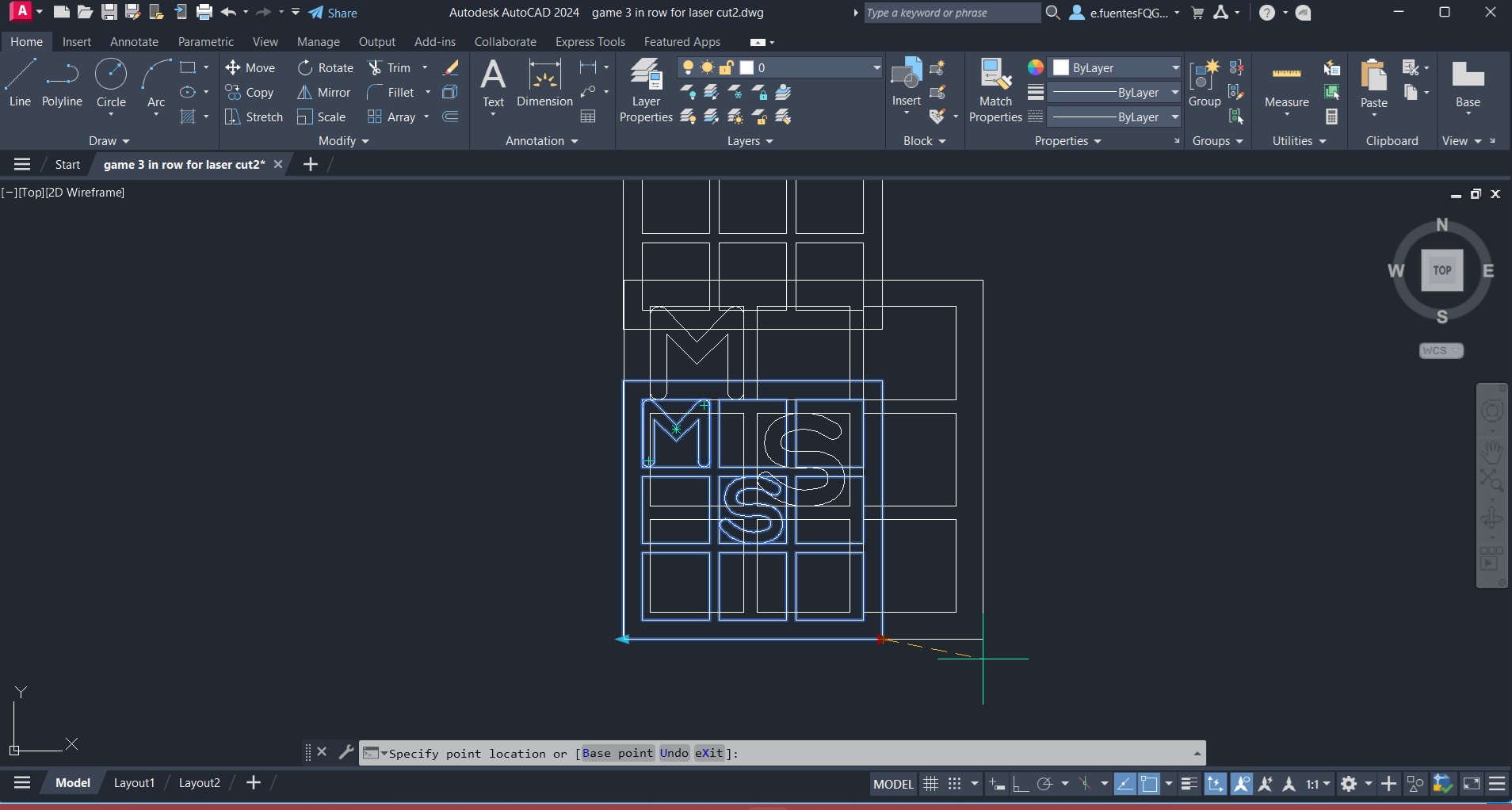
The transition from concept to reality began in AutoCAD, where I drafted the geometry at a 1:1 scale. I designed each module to be 35 mm, a dimension chosen to feel comfortable and manageable in a child’s hand.
Inside each module, I incorporated the letters M and S as the initials of my children’s names, adding a personal and emotional layer to the project.
To optimize material usage and work more responsibly, everything was organized within an A4 horizontal format. Once the drawing was completed, I exported and opened the .DWG file in the Epilog Engraver software.
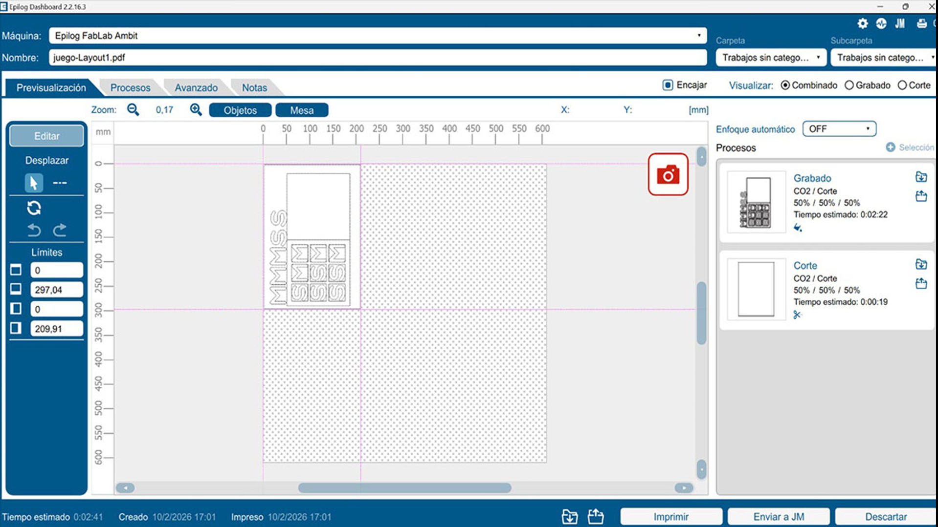
Main preparation steps:
Drawing in AutoCAD
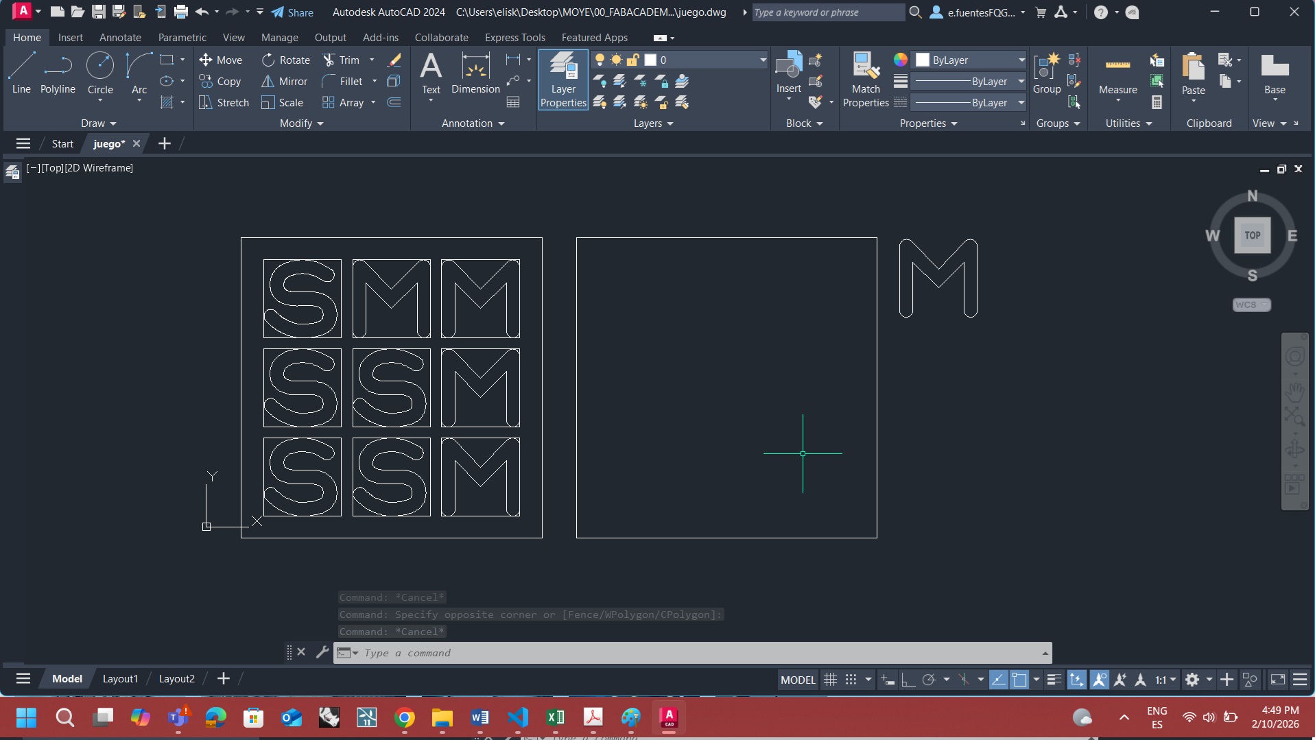
Drawing in AutoCAD
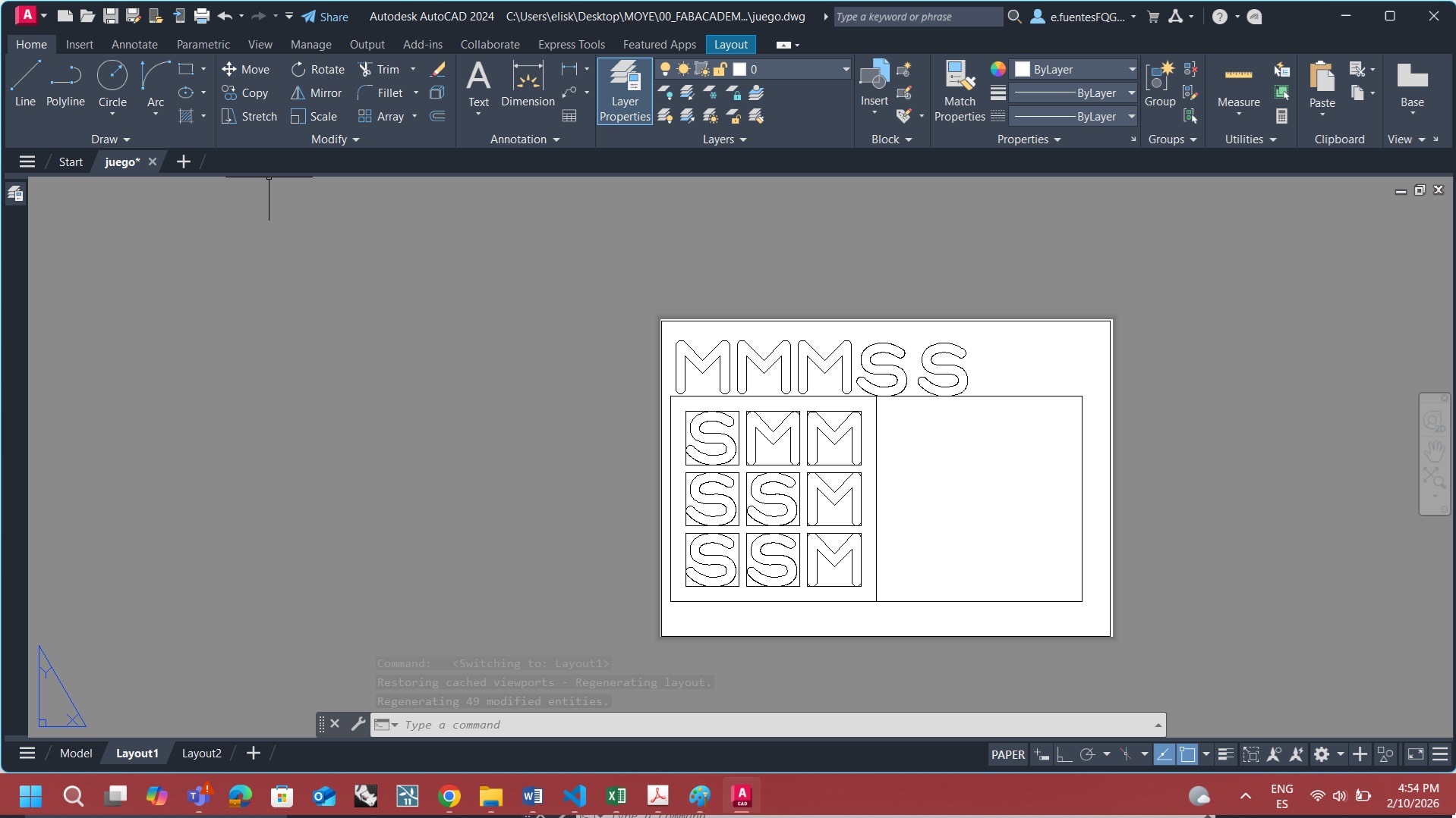
Layout
Layout
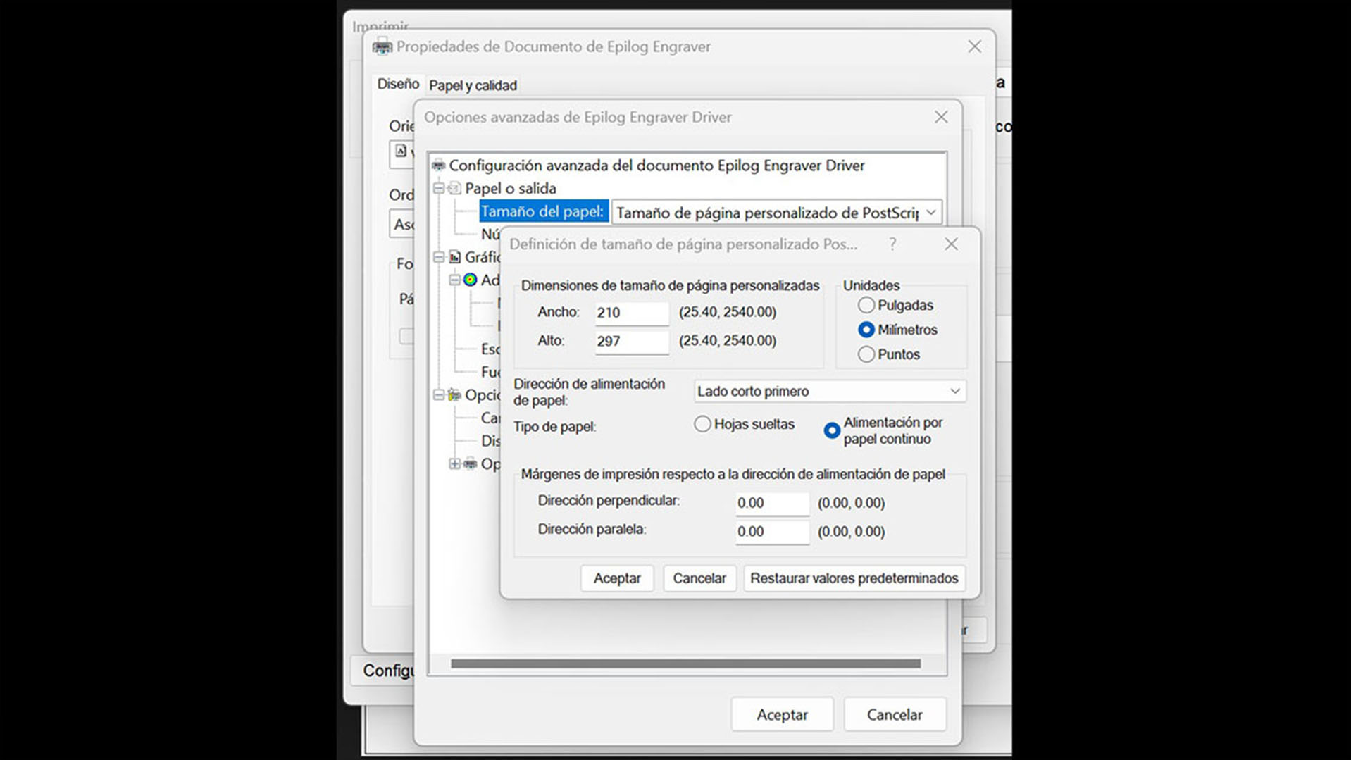
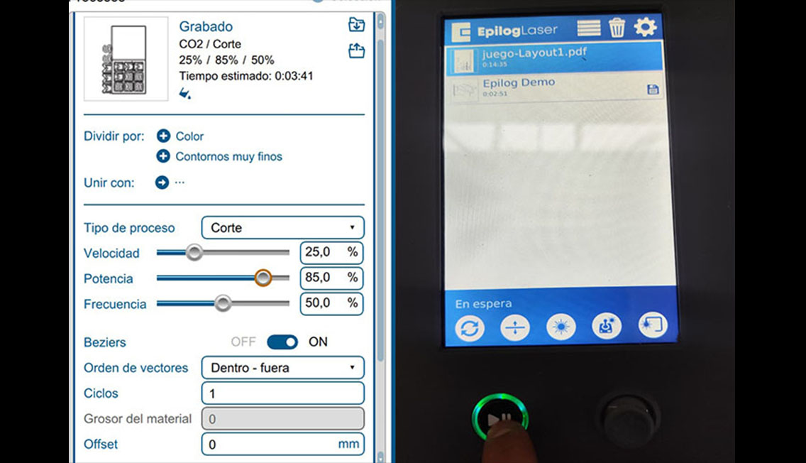
Epilog settings
Laser cut layout
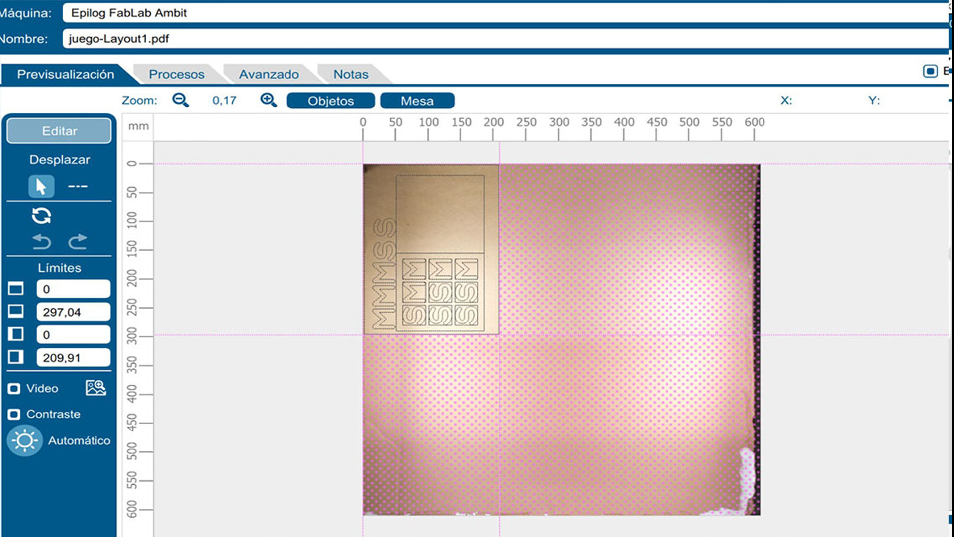
For the material, I chose to work with recycled corrugated cardboard, aligning with the sustainable spirit of the project.
I configured the laser for a vector-only cut, skipping engraving to maintain a clean and bold design.
Laser cutting settings:
Working with recycled material also introduced some challenges. Due to the inconsistent density of the cardboard sheets, the laser did not always cut perfectly through the core. This required a more patient and hands-on process to manually separate some pieces from the board.
This experience became an important reminder that digital precision must always adapt to the imperfections of real materials.
After a quick assembly using glue to reinforce the structure, the game was finally ready.
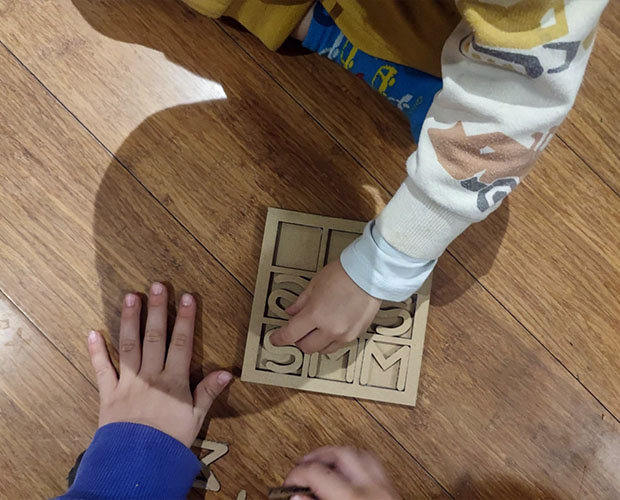
Seeing the children immediately choose the “M” and “S” pieces and start playing was the best validation of the project. It was not only a technical exercise, but also a small piece of interactive micro-architecture capable of creating an instant and joyful connection between players.
Setting the laser cut
Setting the laser cut
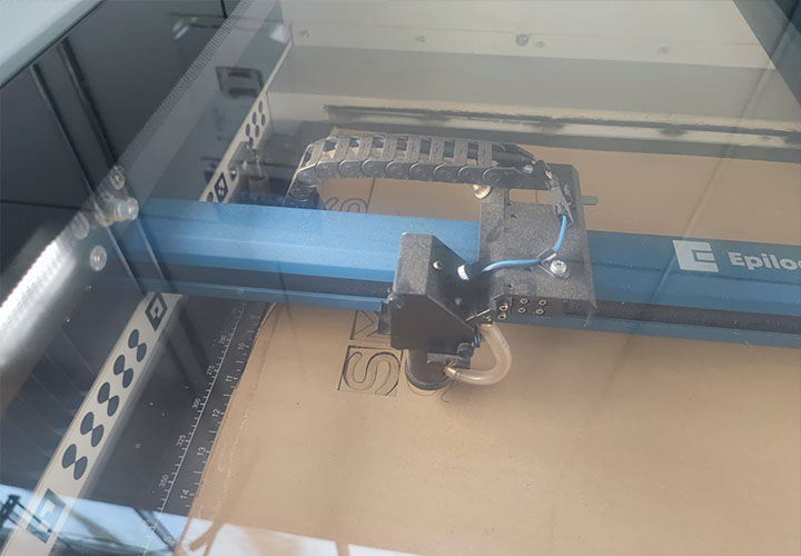
Cutting process
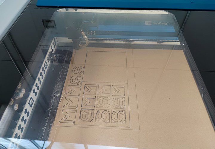
The result of the laser cut
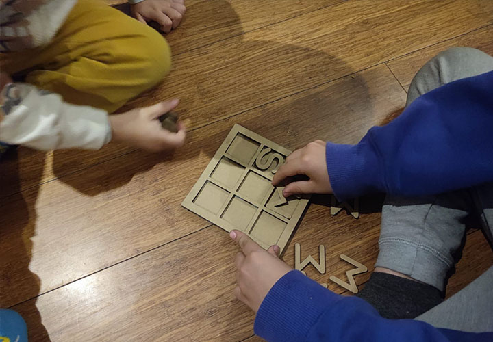
Play time
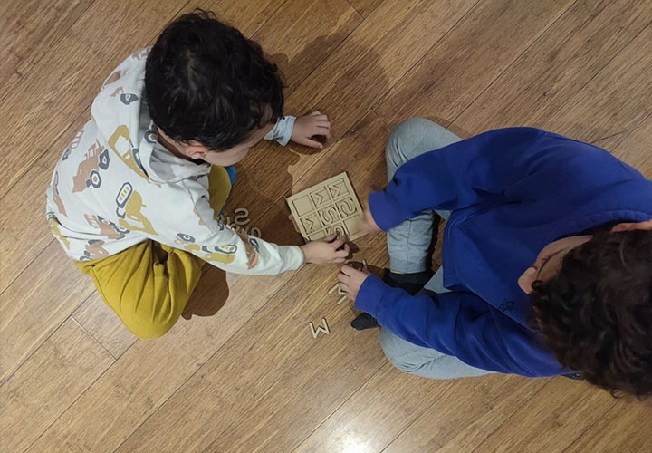
Play time
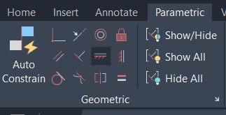
In AutoCAD, parametric design tools allow relationships and dimensions to be assigned to geometric elements so that modifications can be made efficiently while maintaining design intent. In architectural drafting, these tools are commonly used to keep walls parallel, ensure columns remain aligned at grid intersections, and maintain consistent spatial relationships throughout a drawing.
For the Three-in-a-Row game, the most relevant application of parametrization was the ability to modify the overall size of the game board as well as the dimensions of the M and S playing pieces. One approach would be to use dimensional parameters controlling the height and width of the components, allowing all related elements to update automatically when values are changed.
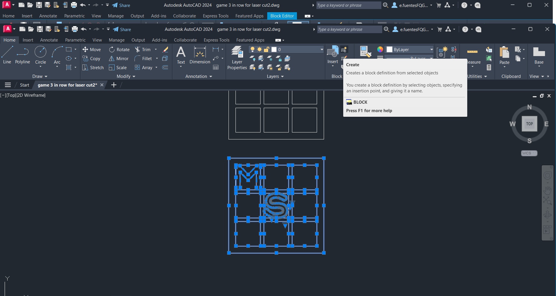
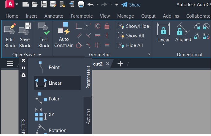
However, an even simpler solution was achieved using Dynamic Blocks. Within the Block Editor, a Linear Parameter was added to the game model .
A Scale Action was then associated with this parameter, enabling the entire game to be resized proportionally.
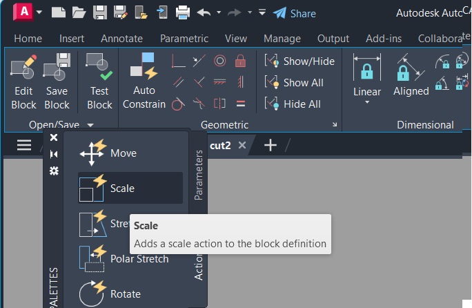
Once the dynamic block was created, AutoCAD displayed a control arrow that allows the user to interactively adjust the size of the complete game simply by dragging the parameter grip. This method provides a quick and intuitive way to generate different game sizes while preserving all proportions and geometric relationships.
Vinyl cutting is a digital fabrication process that uses a computer-controlled cutting plotter to create precise shapes and graphics on adhesive vinyl and other thin materials. The machine follows vector lines created in design software, transforming digital drawings into physical elements with high accuracy. Unlike laser cutting, the blade cuts only the vinyl layer while keeping the backing paper intact.
During this assignment, we learned how to prepare vector files correctly and understand the relationship between digital design and machine fabrication. As architecture students, this process helped us improve our understanding of scale, geometry, and precision in digital manufacturing workflows. We also experimented with machine parameters such as cutting speed and force to achieve clean and accurate cuts depending on the material type.After cutting, we performed the weeding process by removing the excess vinyl and keeping only the desired design. Finally, transfer tape was used to apply the graphic onto another surface. This workflow introduced us to an accessible and versatile fabrication technique that can be applied in architectural graphics, signage, prototyping, and model-making.
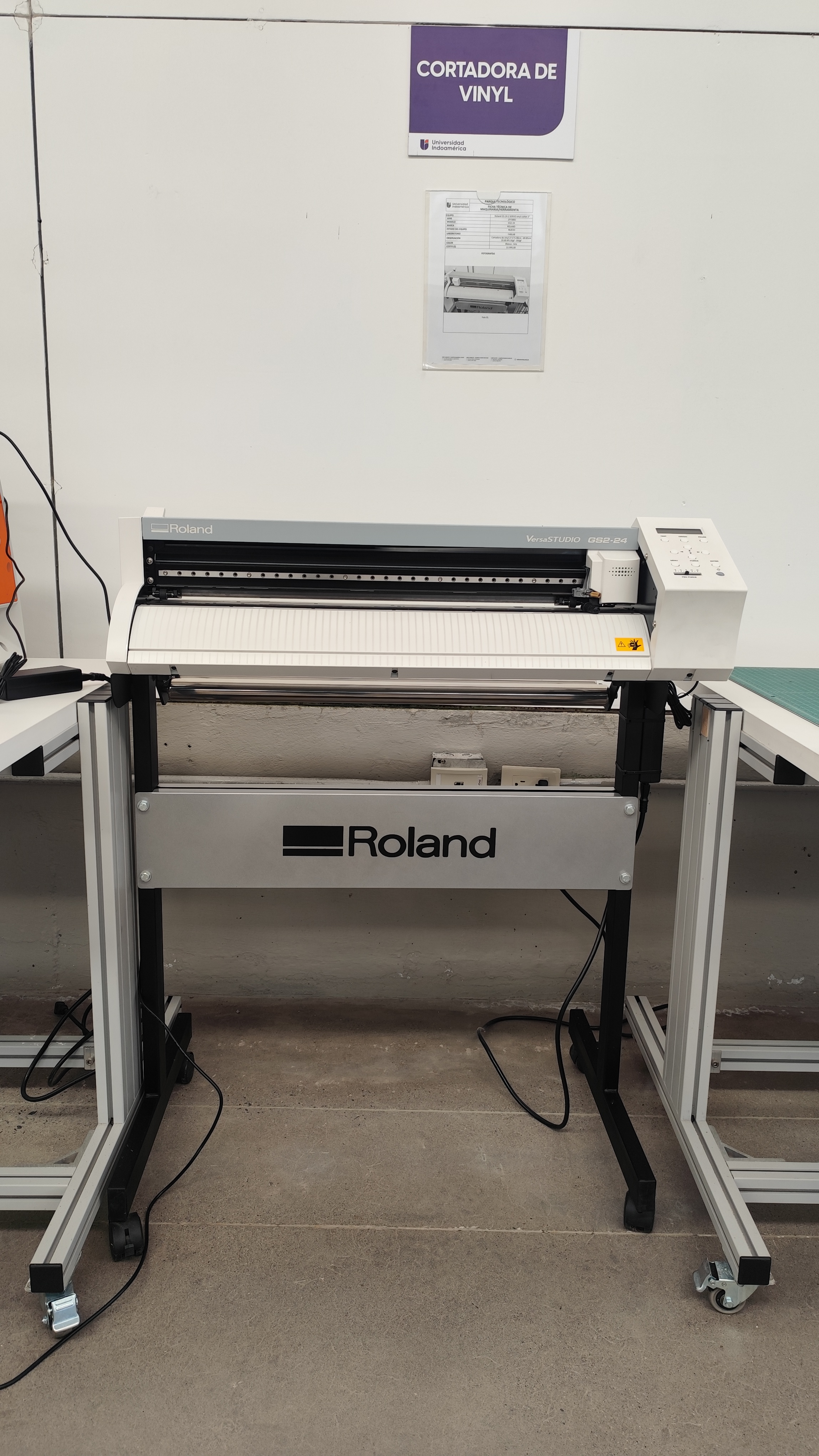
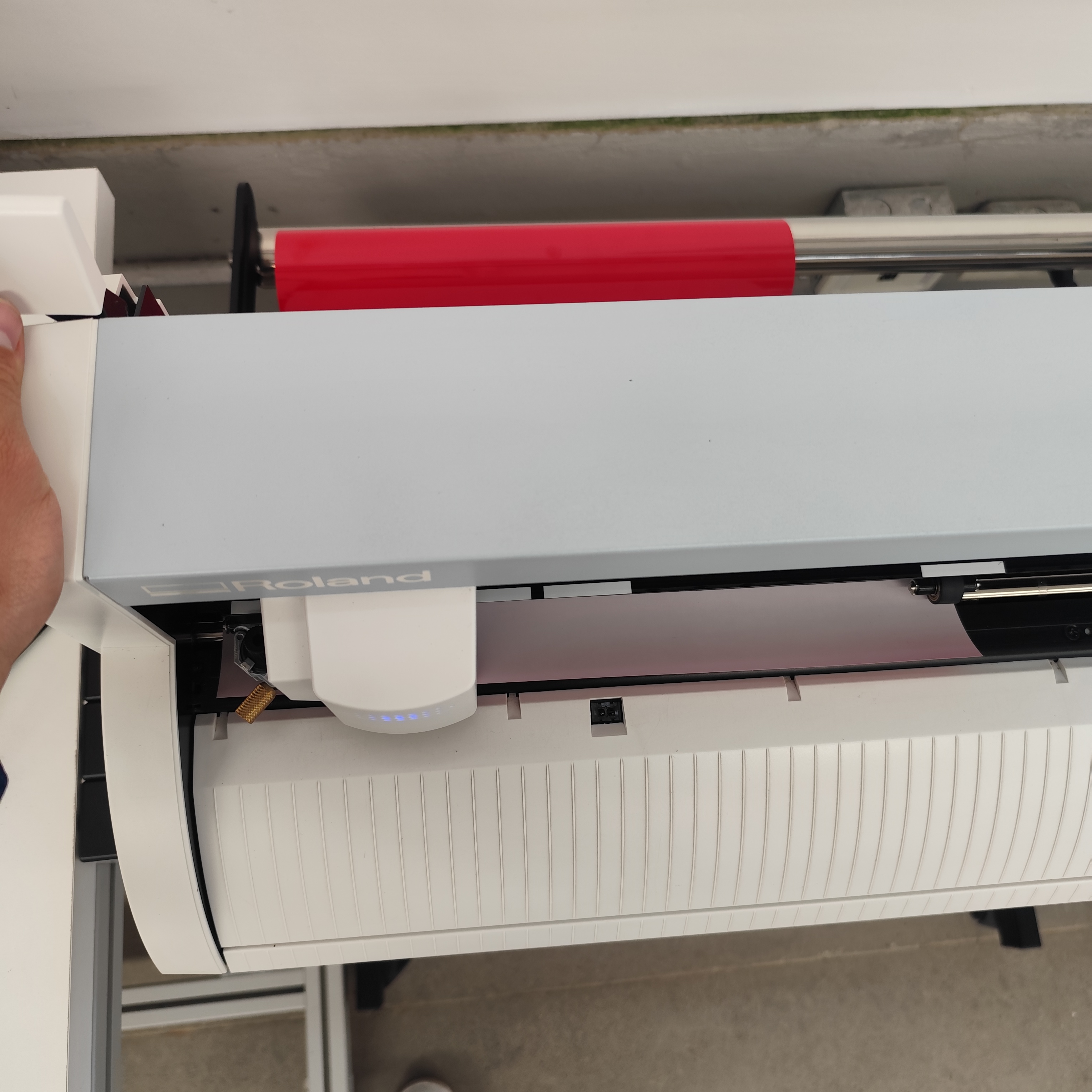
Our digital fabrication laboratory is equipped with the Roland VersaSTUDIO GS2-24 vinyl cutter. During the assignment, we used this machine to understand the complete workflow from digital design preparation to final fabrication.
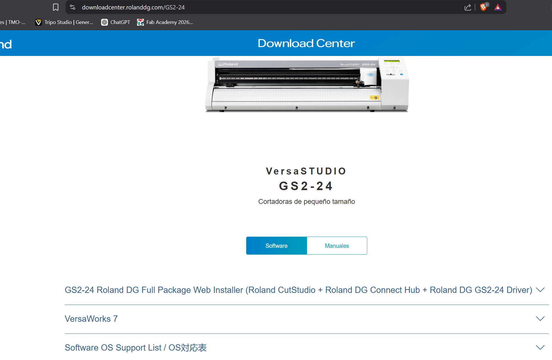
To operate the vinyl cutter, we first installed the Roland CutStudio software, which is easy to access and install on both Windows and macOS systems.
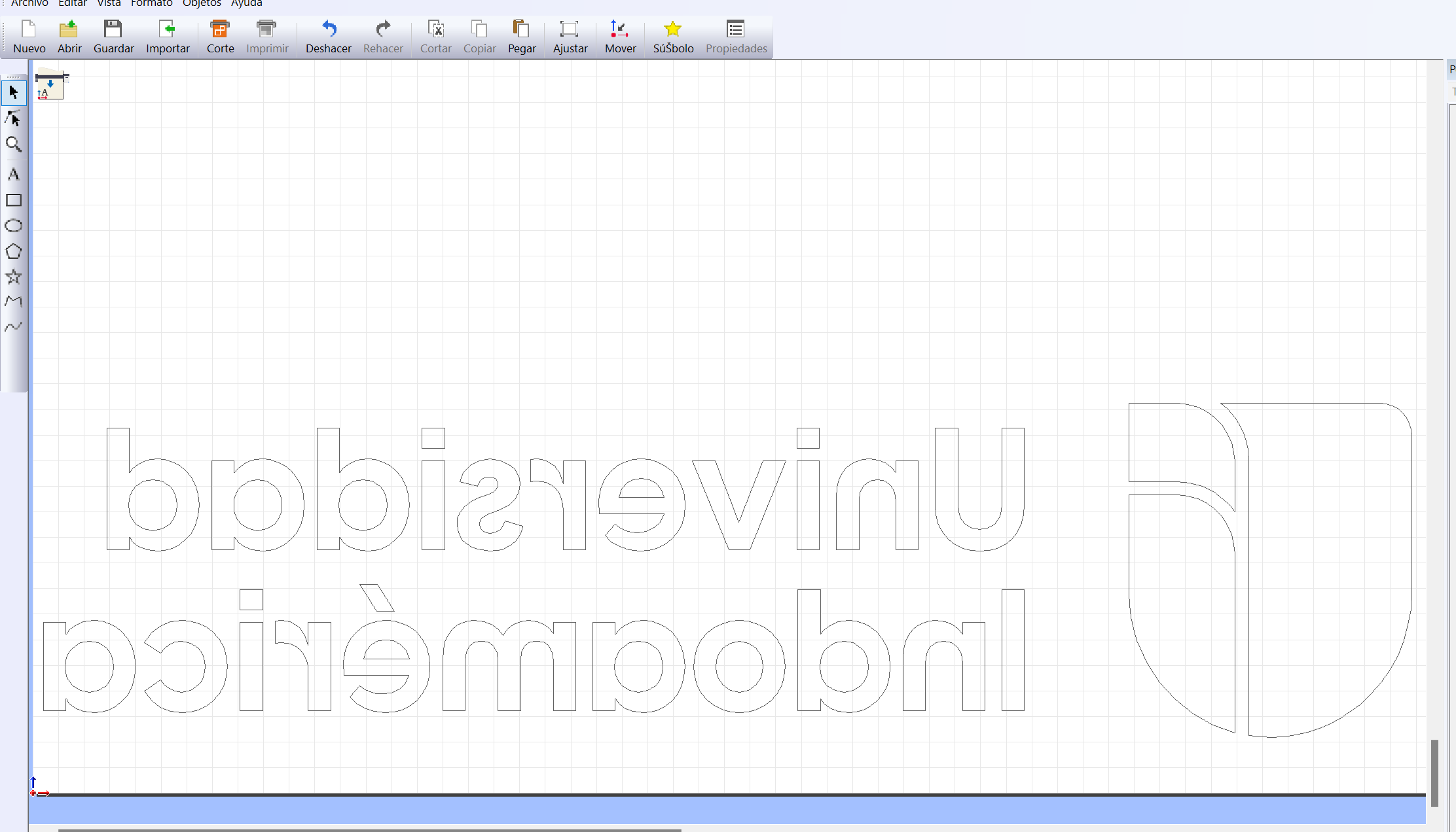
Once the software was installed, we imported the vector files that we wanted to cut. In our case, we used the laboratory logo created in AutoCAD. To load the vectors into CutStudio, we simply copied the drawing from AutoCAD and pasted it directly into the software.
Inside CutStudio, we adjusted the position of the design according to the vinyl area and corrected the dimensions to obtain the desired cutting size.
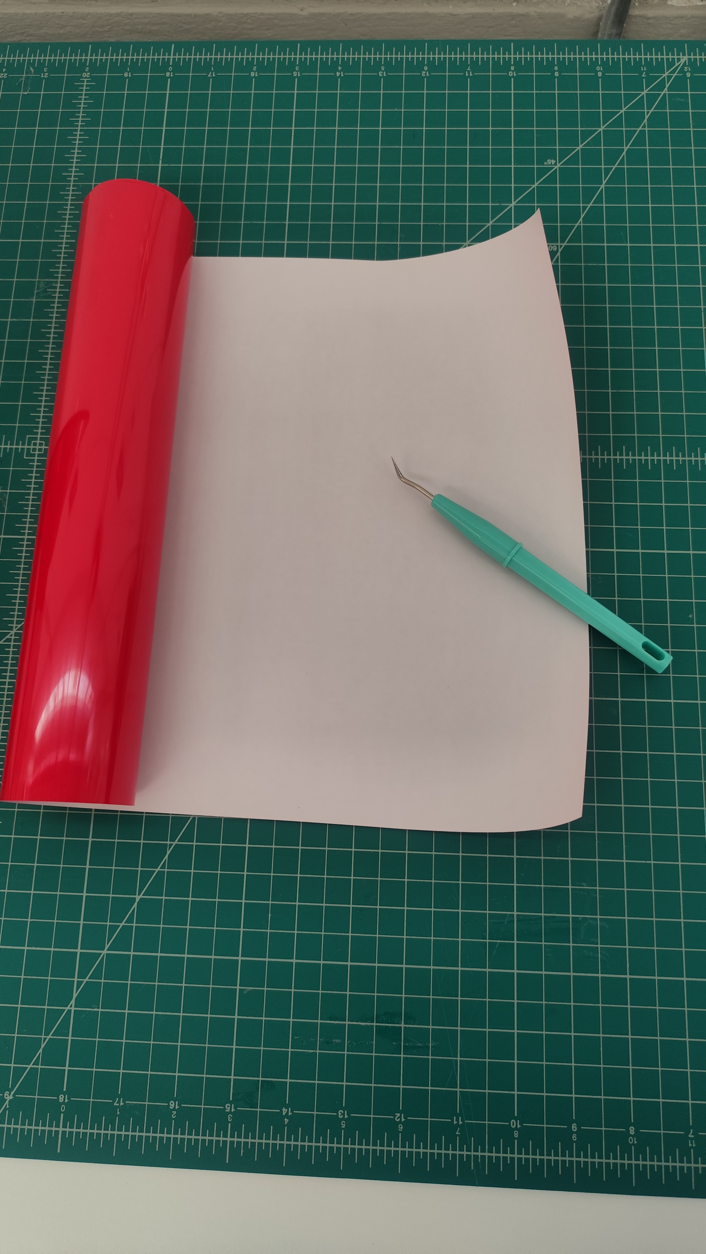
For this practice, we used a red heat-transfer textile vinyl. This material is commonly used to transfer graphics onto fabric surfaces using a heat press.
The vinyl material was loaded from the back side of the machine. After placing the material correctly, we pushed the lever down to secure and adjust it in place.
Next, we configured the material setup in the machine interface. In our case, the selected material format was a vinyl roll.
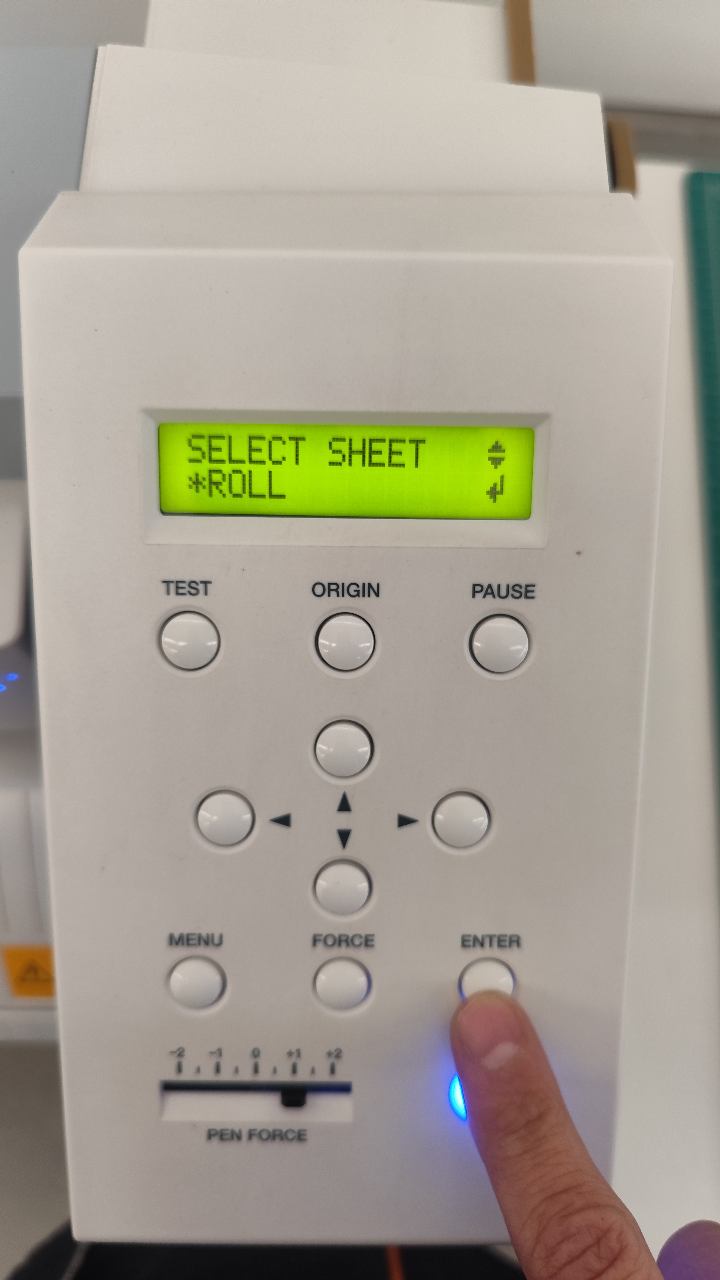
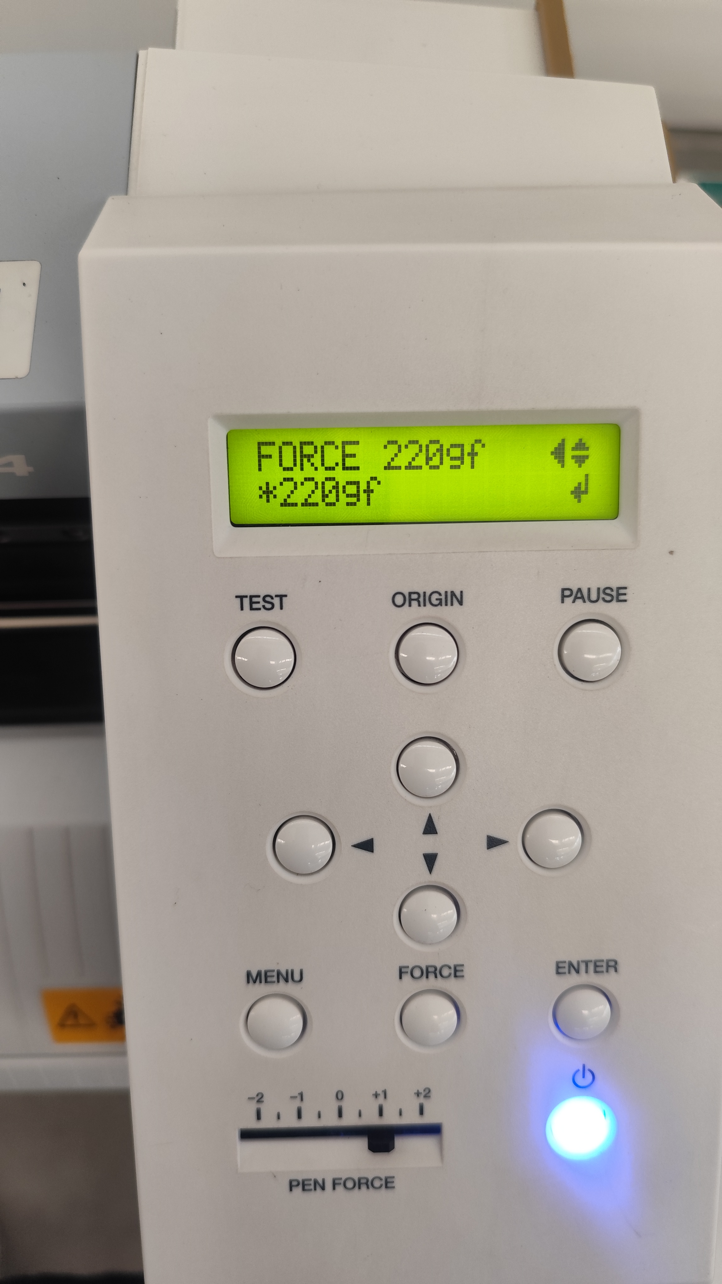
Finally, we configured the cutting force according to the material type. For this textile vinyl, the machine was set to a cutting force of 220 gf to achieve clean and accurate cuts.
During Week 3, we explored laser cutting and vinyl cutting as digital fabrication technologies that play an important role in contemporary architectural practice. These processes allowed us to understand how digital design can be translated into precise physical results through computer-controlled manufacturing methods.
From an architectural perspective, laser cutting is especially valuable for the development of study models, façade explorations, structural prototypes, and interior design components. Its precision and speed make it an efficient tool for both academic experimentation and professional workflows.
Similarly, vinyl cutting demonstrated strong applications in architectural graphics and spatial communication. This technique can be used for logos, signage systems, interior graphics, exhibitions, and wayfinding elements, which are essential components in the design of functional and visually coherent spaces.
As an architect and architecture professor, these digital fabrication tools are particularly relevant because they strengthen the connection between conceptual design, technical production, and material experimentation. They also provide new opportunities for teaching design methodologies and integrating fabrication technologies into architectural education and professional practice.