Week 17
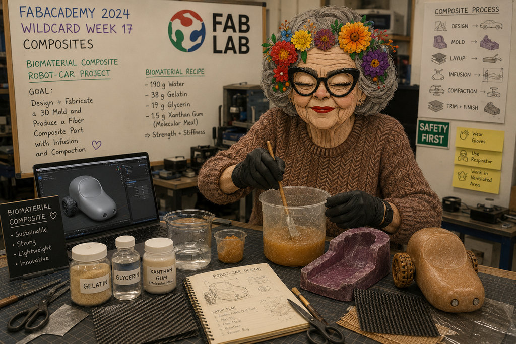
AI prompt:
“FabAcademy 2026 – Wildcard Week 17: Composites. Granny with flower crown and glasses working in a Fab Lab on a robot-car biomaterial composite project, mixing gelatin, glycerin, xanthan gum, and water. Blender car design on screen, composite mold, fabricated car part on table, workshop tools, safety posters, maker atmosphere.”
Wildcard Week
This week I needed to design and digitally fabricate something (including computer design and fabrication) that had not been covered in any previous assignment. I read through the possible options for this week and ended up choosing the last option in the list: Composites 😅
This one immediately caught my attention and I really wanted to try it because I also needed to design the body of my car for my final project. So I decided to use this week as another opportunity for interesting experiments.
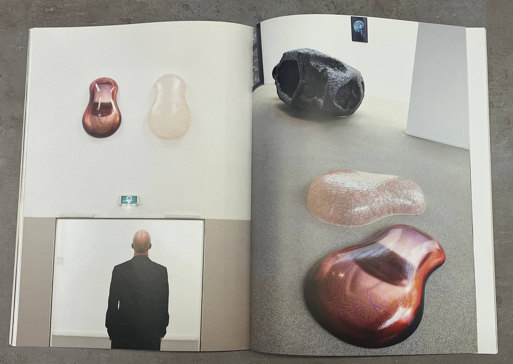
I should also mention that a few months ago Anush, one of our lab staff members who is also a FabAcademy and FabriAcademy instructor, brought a book from Amsterdam specifically about creating car composites from a humorous perspective. That book inspired me even more, and with Anush’s help we started working on this week's assignment.

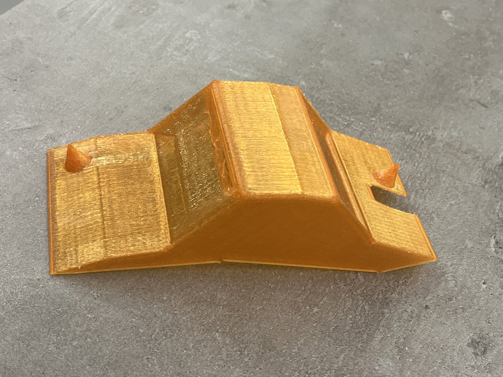
First I will show the version that I had already designed and printed for testing purposes, then continue with the main design process.
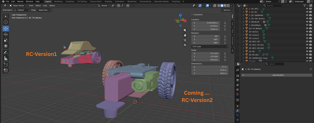
I started by arranging all the internal components that would fit inside the car body.
Once everything was positioned correctly, I created a Cube, then pressed Ctrl + R to create loop section so I could shape the body by moving the generated sections.
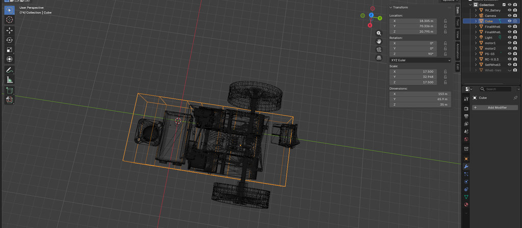
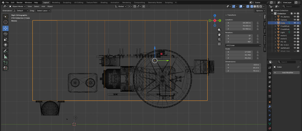
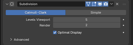
After that I selected the cube and applied: Add Modifier → Generate → Subdivision
Then I set Levels Viewport = 5 to get the desired smooth curved shape.
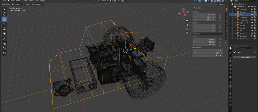
Afterwards I started subtracting spaces from the main body according to the dimensions and positions of the imported models.
Let’s start with the Toggle Button.
I placed it where I wanted the opening to be, selected the button model, switched to Edit Mode, duplicated the required points, gave them thickness, filled the surface by pressing F, and repeated: Add Modifier → Generate → Boolean
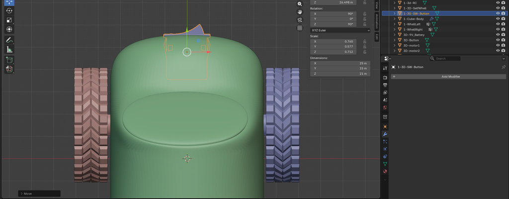
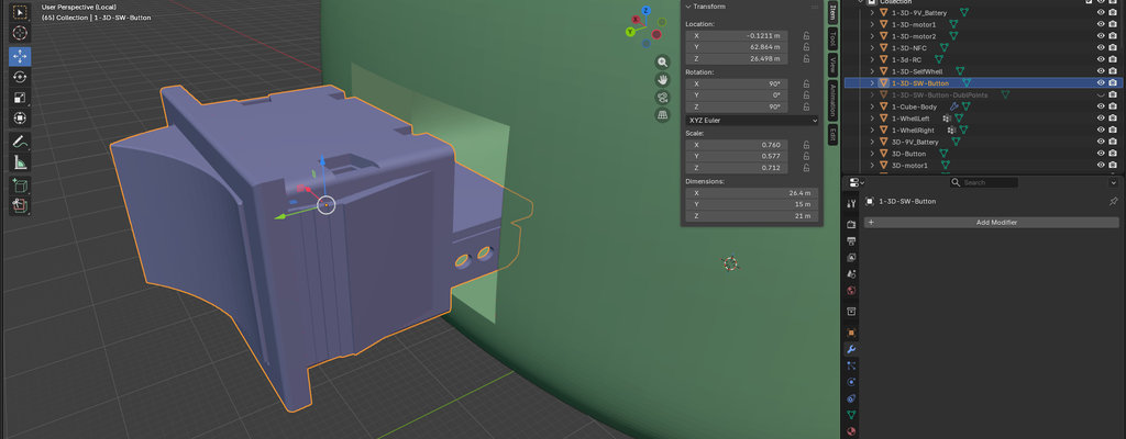
Then I selected the duplicated object with the eyedropper and pressed Apply.
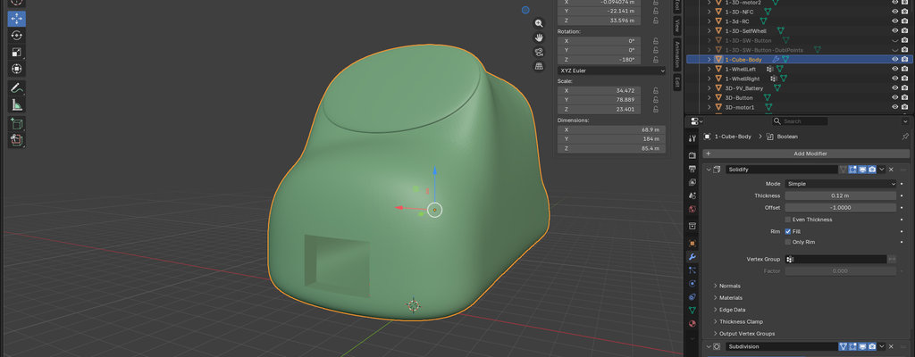
Then I repeated the same subtraction process for all the objects.
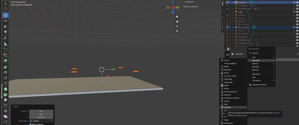
For the self-adhesive caster wheel, I again selected the surface and to fill the inside I chose: Add Modifier → Generate → Solidify
Then I increased the Thickness value until the inside became filled. However, I noticed that some surfaces were facing inward while others were facing outward, so I pressed L to select all connected surfaces and then selected: Mesh → Normals → Recalculate Outside to correct the directions.
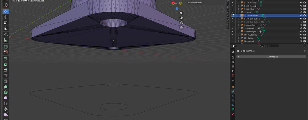
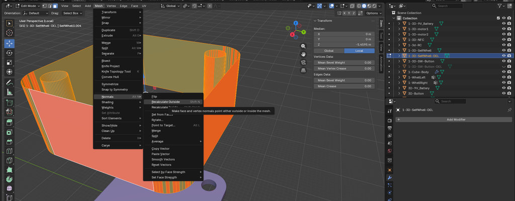
After that, I duplicated only the inner ring sections and performed the Boolean operation(Difference) on the car body.
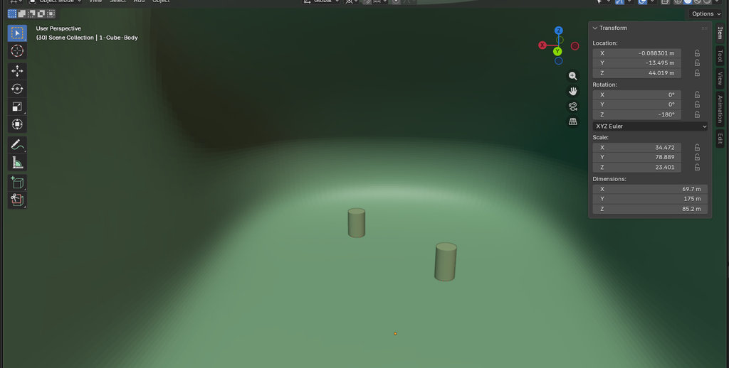
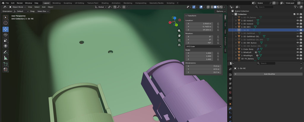
Next, I moved to creating the corresponding holes for the NFC Reader from the bottom side of the car, because I planned to mount the NFC module on the lower part.
Since I was also planning to mount the motors on top of the NFC board, I created a new Cube and adjusted its Scale so it would create support holes matching the inside dimensions for mounting the NFC properly.
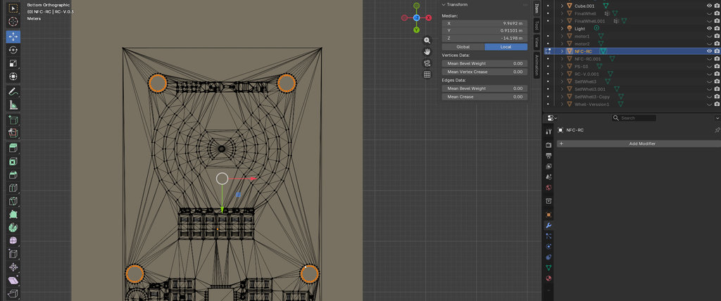
Then I created another cube and adjusted its scale so the motor could be mounted to it with bolts using the motor's mounting holes. I duplicated this setup symmetrically.
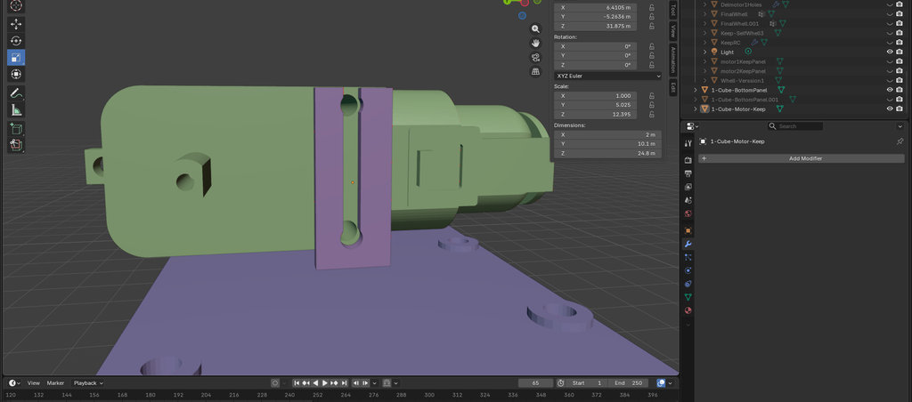
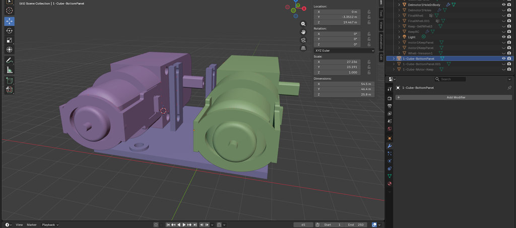
Here is an image of the bottom section of the car.
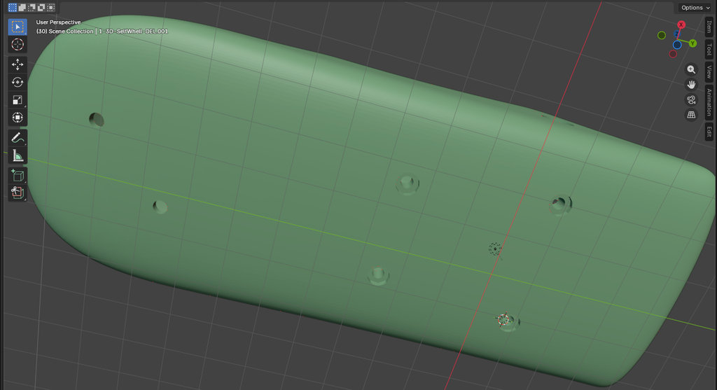
Then I created another similar cube that would be placed above the motors to mount my PCB on top of it. For that, I duplicated the hole positions from my PCB and subtracted them from this platform.
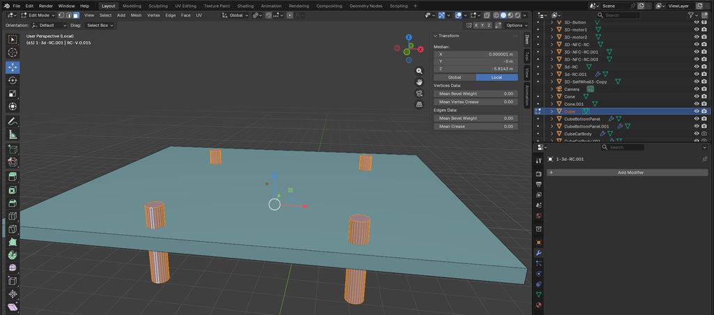
Then I also subtracted this new cube from the inside of the main car body so it would extend outside the car and create something like a small door-line effect.
Next, for allowing the wheels to rotate freely outside the motors, I selected the corresponding motor hole area and enlarged it enough so that rotation would not interfere with the body, then subtracted the resulting shape from both sides of the car.
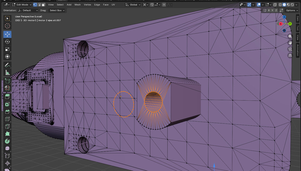
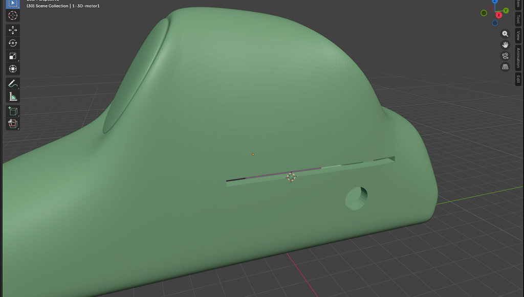
Here is an image of the USB hole in the car.
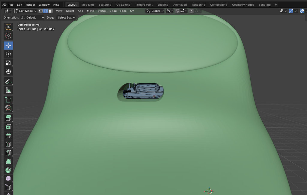
Now it was time to split the car into two parts for printing.
For that, I created a panel: Add → Panel.
Then I positioned it where I wanted the cut and again performed a Boolean operation.
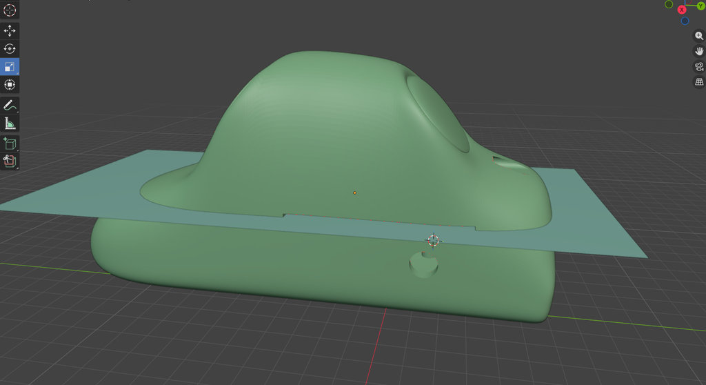
Here are the two parts of the car after splitting.
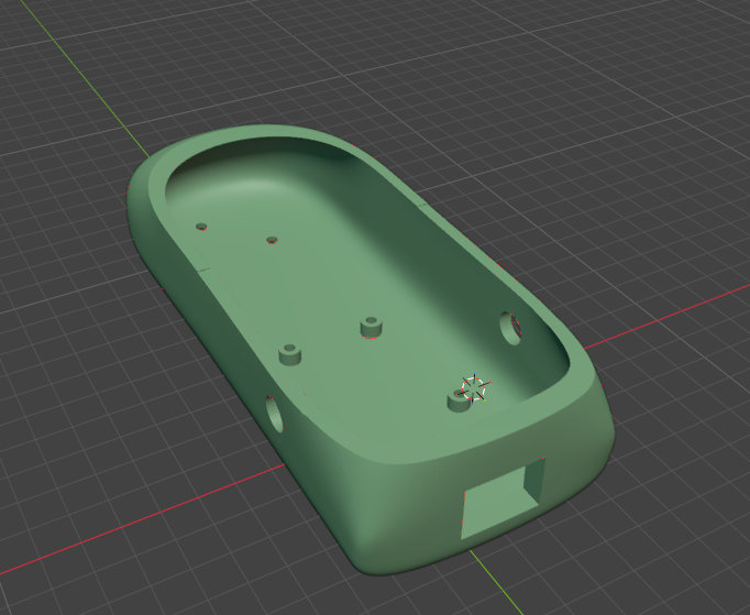
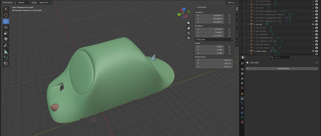
Here are the final parts of the car.
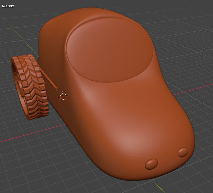
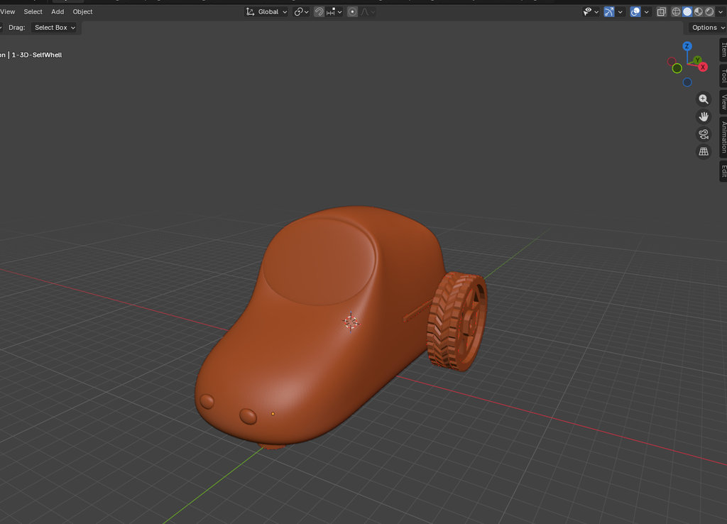
Here is the complete car shown in video format.
Here are the screenshots from OrcaSlicer.
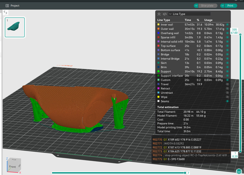
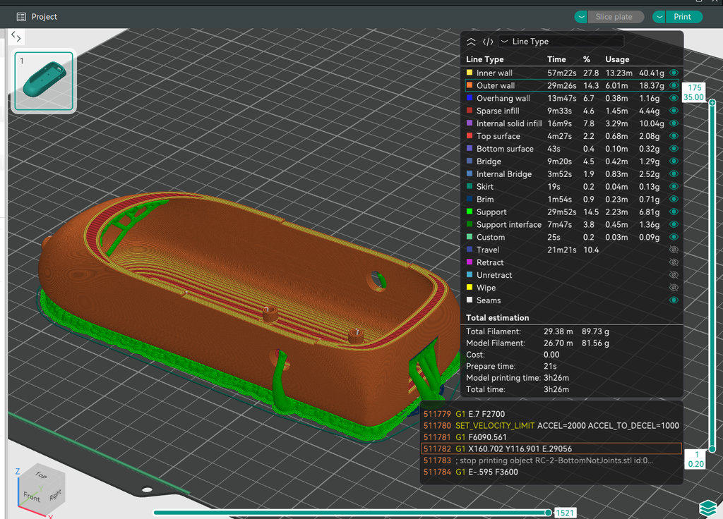
And now it finally looks like everything fits.
I am planning to connect the two car body parts using magnets, which I will show later.
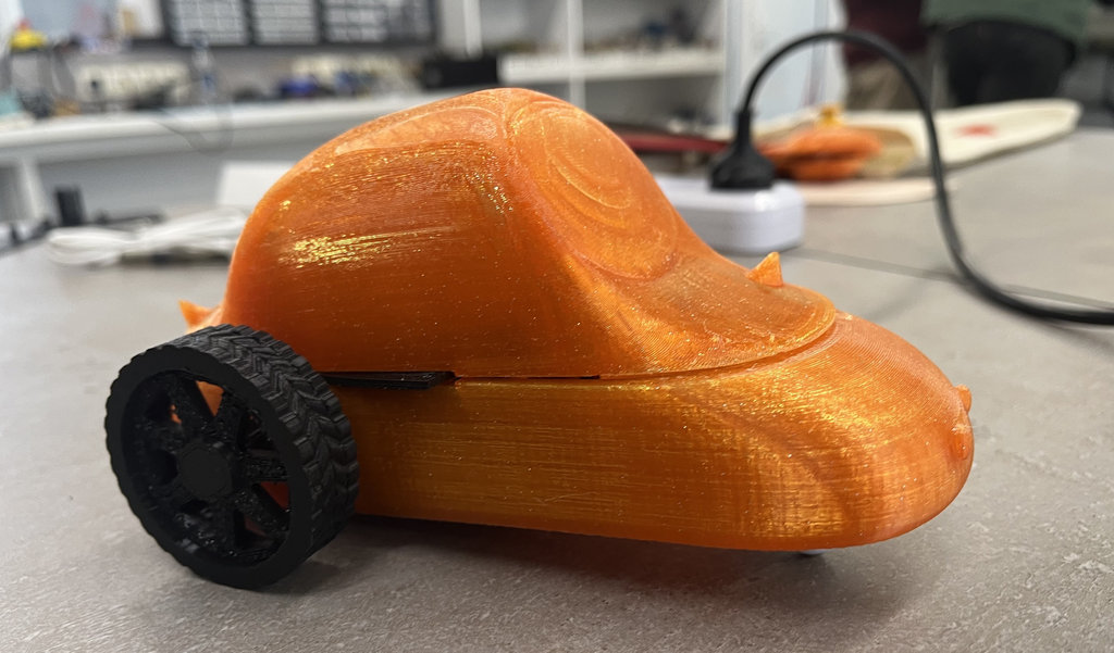
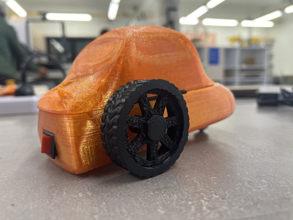
My car actually looks really beautiful 😍😍
Composite Creation Process
Now let’s move to the composite creation part.
Composite materials (or composites) are engineered products made by combining two or more distinct materials. Because these original ingredients do not fully dissolve or blend together, the final material retains the unique, beneficial properties of each individual component while gaining entirely new advantages like enhanced strength, durability, or weight reduction.Composites and reinforced materials offer significant performance advantages over traditional materials like steel, aluminum, wood, and unreinforced plastics.
- High Strength, Low Weight: They are stronger than steel but weigh much less.
- Rust Proof: They do not corrode, rot, or degrade in harsh environments.
- Flexible Shapes: They can be molded into complex, seamless designs.
- Long Lasting: They withstand heavy, repetitive stress without cracking.
For this, Anush helped me — the same person who inspired my interest in that book mentioned earlier, and who is also a FabAcademy and Fabricademy instructor and generally a wonderful person ❤️
Anush suggested creating a biomaterial with the following composition:
Gelatin- 38g- Role: Serves as the primary structural polymer network.
- Mechanism: It dissolves in hot water and forms a strong, interconnected triple-helix gel network as it cools.
- Impact: Provides the biomaterial with its baseline mechanical strength, shape, and solid form.
Glycerin- 19g- Role: Acts as a plasticizer to provide flexibility.
- Mechanism: It embeds between the rigid polymer chains of the gelatin, increasing the free space and molecular mobility.
- Impact: Prevents the final material from becoming overly brittle, stiff, or cracking when dry.
Water- 190ml- Role: Acts as the primary solvent and dispersing medium.
- Mechanism: Hydrates the gelatin powder, allowing the protein chains to untangle, dissolve, and re-align uniformly.
- Impact: Most of it evaporates during the drying process, leaving behind the cured, solid biomaterial.
The heating temperature for a gelatin-based bioplastic mixture is 70°C to 80°C and it is typically heated and simmered for 10-15 minutes.
Before pouring the biomaterial into the ring-shaped section, I wanted to create some design using wool available in the lab.
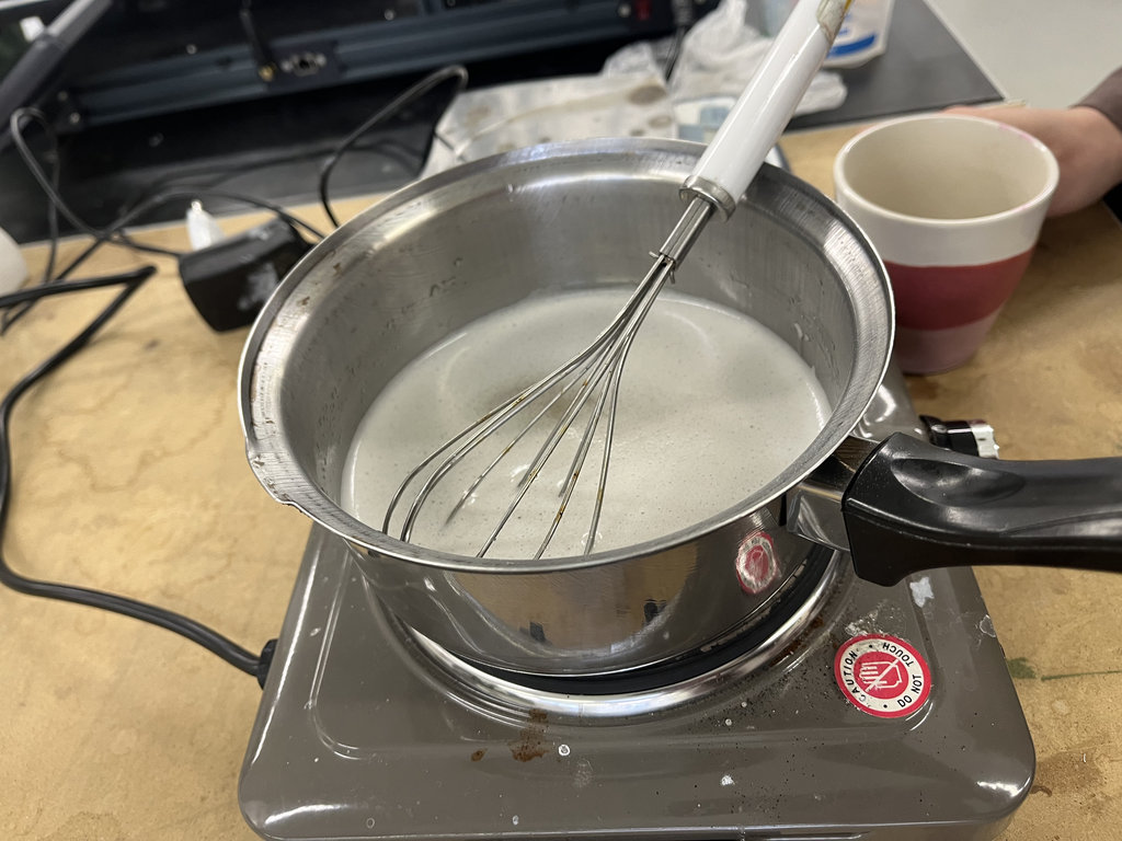
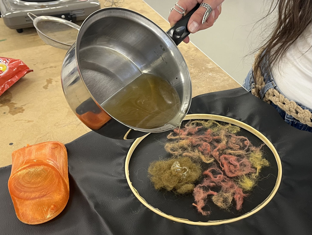
After pouring the material, we waited for one hour and then closed the car using fabric material.
Also I should mention that one of the advantages of working with biomaterials is that you do not need to wear a mask and can even work directly with your hands.
After waiting for one hour, I separated the material from the wooden ring using a knife. Then I tried placing it on the top section of the car, but it cracked and got damaged.
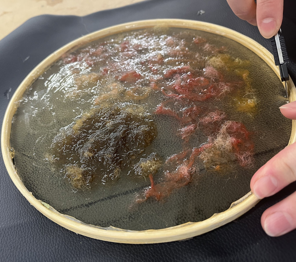
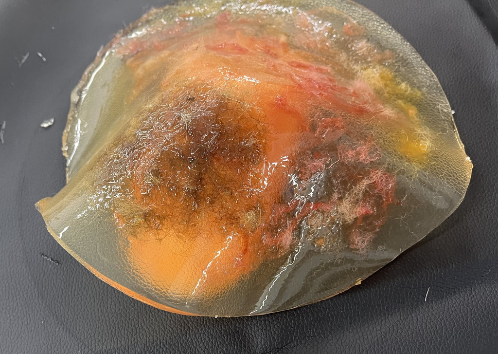
So we made some conclusions. First, the material layer was too thick. We also decided that using fabric to reinforce it on the car body would be a better approach. Because of that, we cut the material into smaller pieces and heated it again until it became a homogeneous mixture, and I removed the wool material.
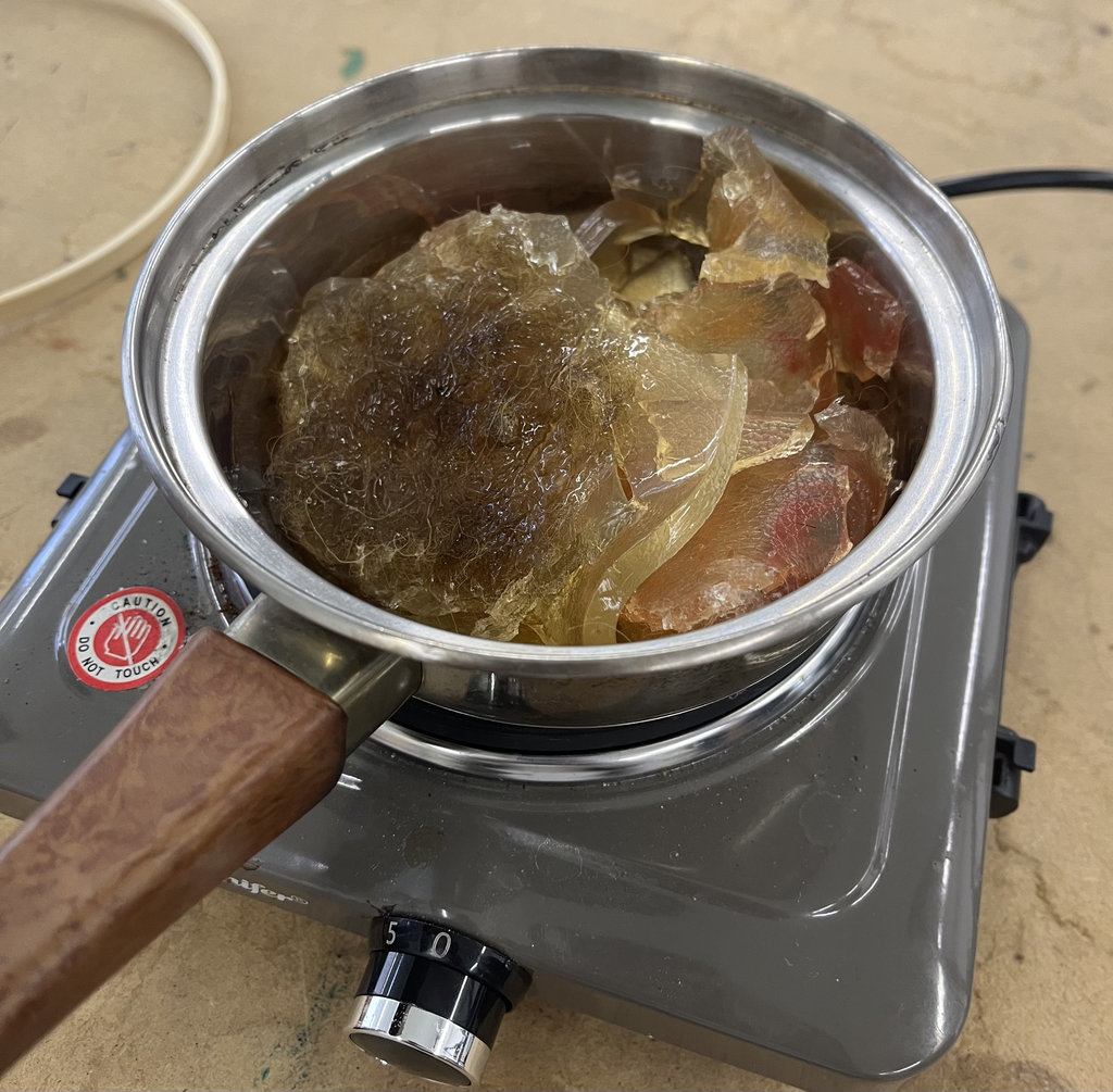
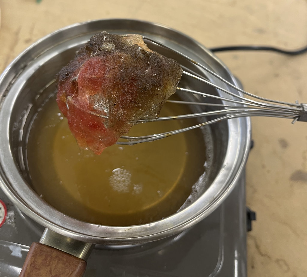
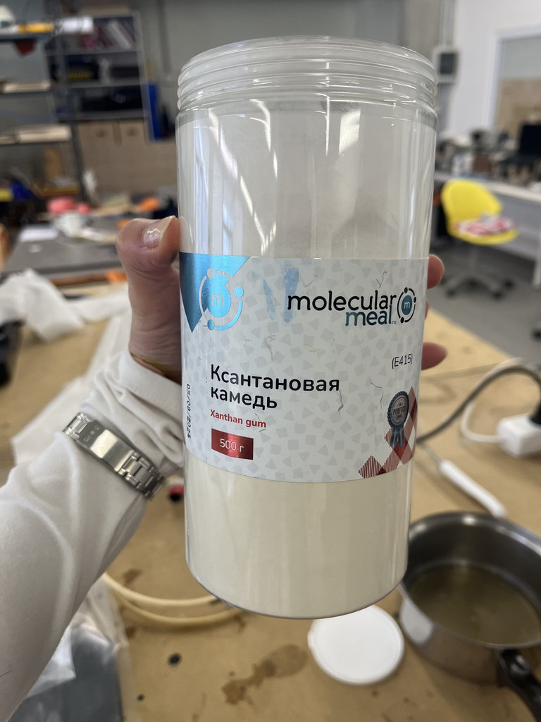
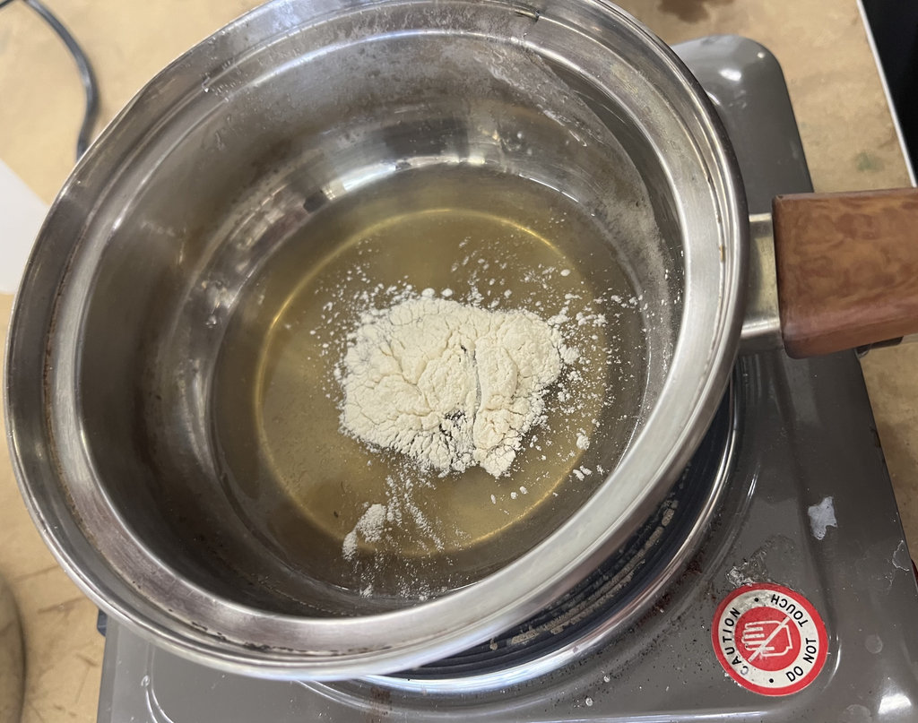
Then we decided to perform one more experiment and added 1.5 g of Xanthan Gum and a small amount of colour powder to make it more visually interesting.
Gum
- Role: Functions as a binder, stabilizer, and thickener.
- Mechanism: It increases the viscosity of the liquid mixture before it sets, preventing the heavy gelatin from settling unevenly.
- Impact: Improves structural uniformity, enhances elasticity, and helps the material retain moisture.
After that I selected two different types of fabric for testing.
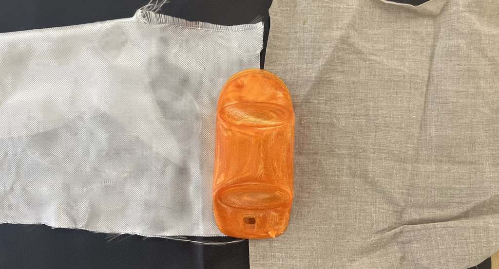
The first one was fiberglass cloth / glass fiber fabric.
For this experiment I first applied the biomaterial onto the outer surface of the car, then attached the fabric to the car body, and finally applied another layer of material on top of the fabric.
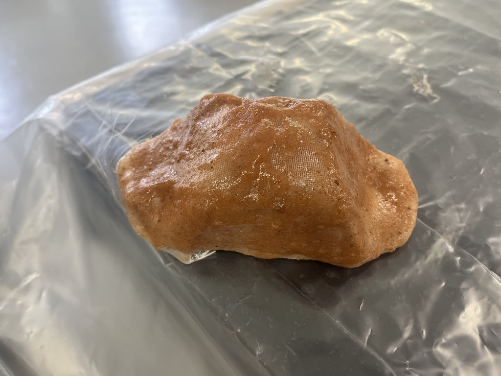
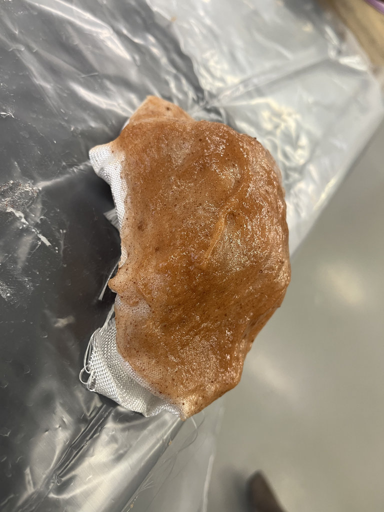
After one day it was ready to trim around the edges. This version was not very strong, but the shape was clearly visible. I will wait a few more days to see how much more it dries.
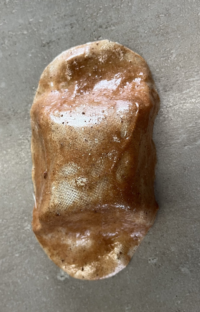
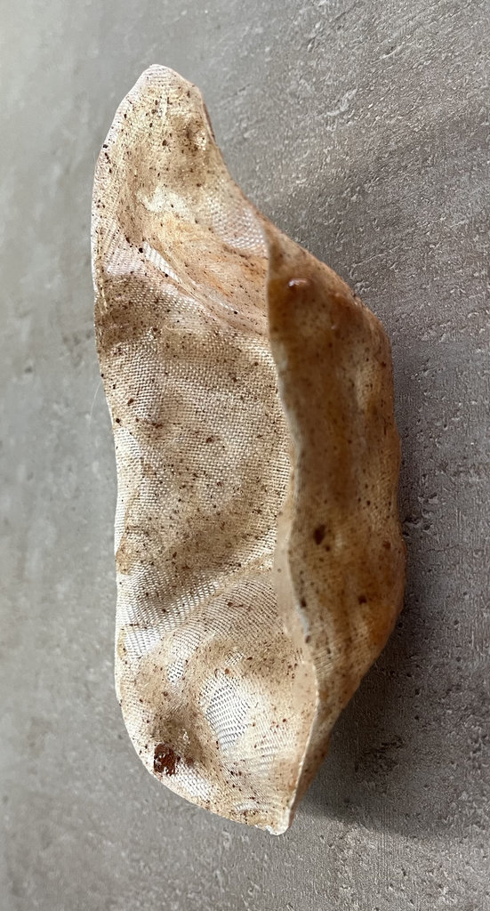
But I already like it.
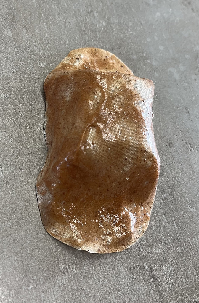
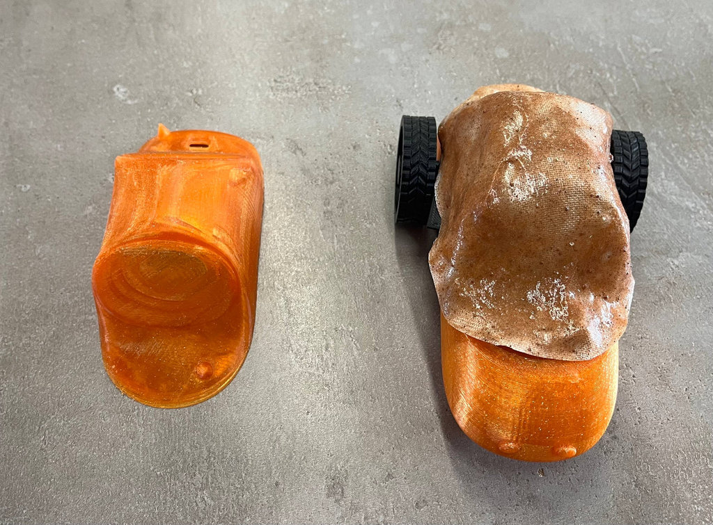
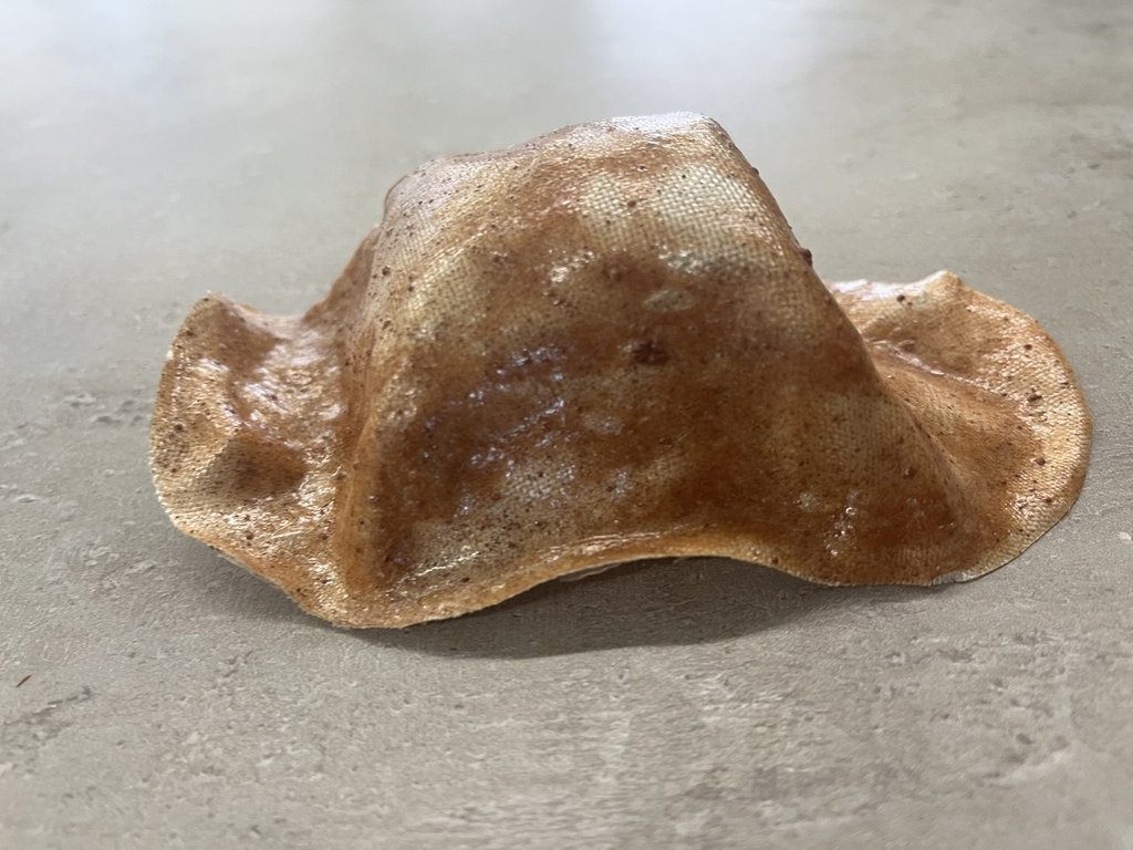
Here is how it looked after ten days, when it was completely dry.
Then I took linen cloth, soaked it in the material, and attached it onto the car body using the matrix material.
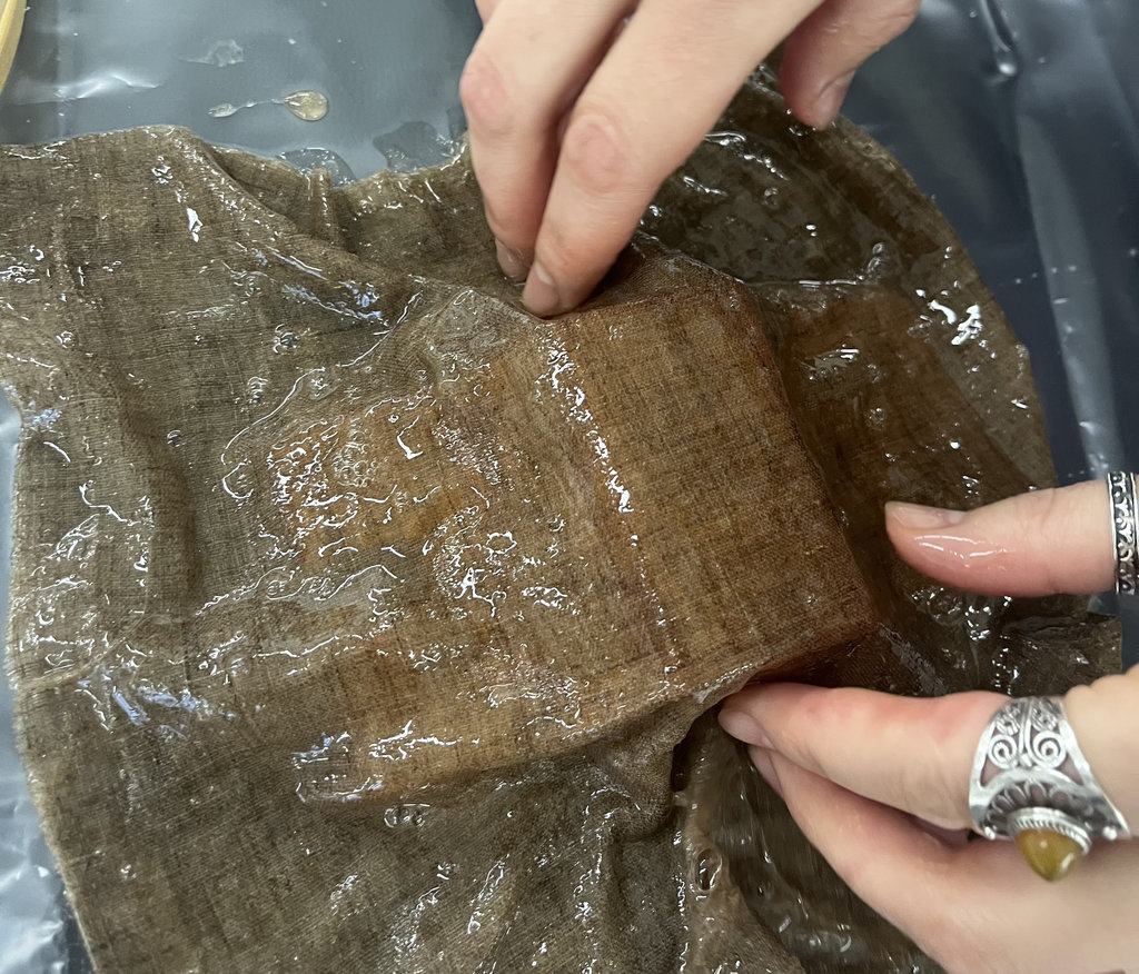
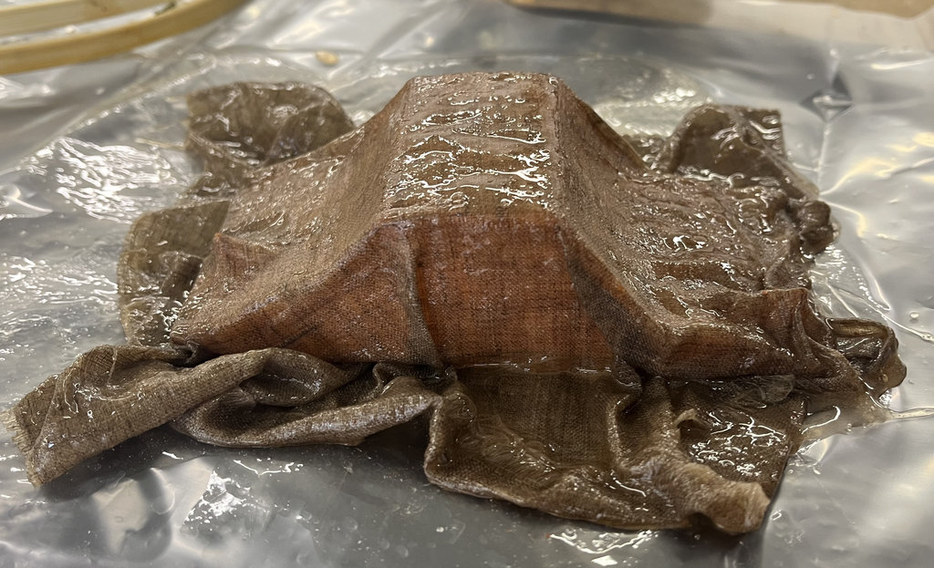
After one day I removed the car again, and the result was much better, although it will still continue drying.
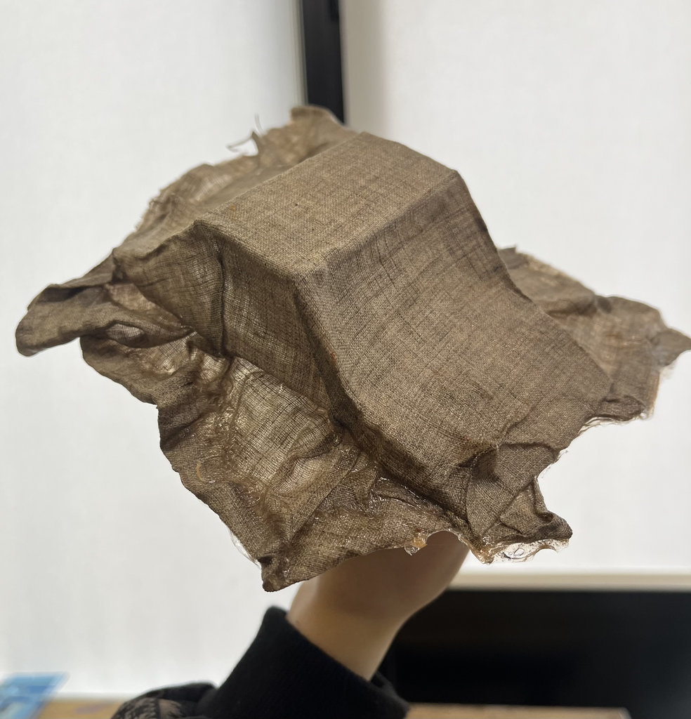
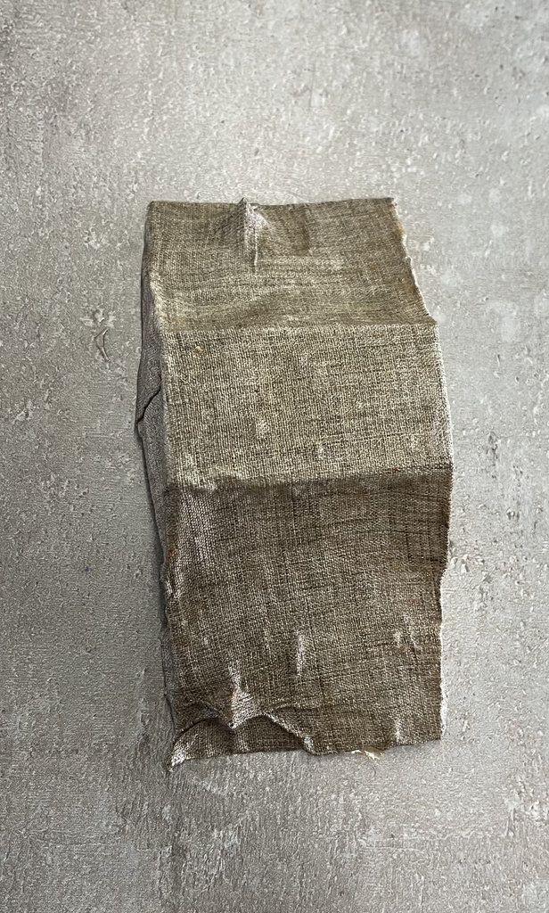
Here is how beautiful and stable it turned out.
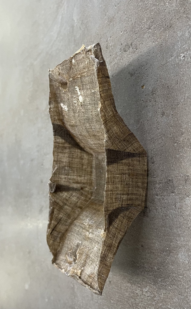
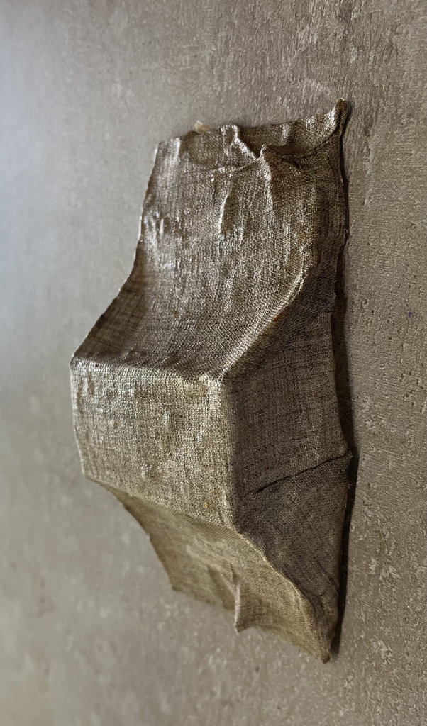
The version made with linen was completely dry after two days. The version made with fiberglass cloth took longer to dry, and since I had already removed it from the machine case during the drying process, it became deformed.
The linen produced better results because its hydrophilic natural fibers thoroughly absorbed the water-based gelatin mixture, creating a strong bond, whereas the hydrophobic fiberglass repelled the matrix and resulted in a weaker composite. Additionally, the flexible, textured nature of the linen allowed for better conforming to complex shapes compared to the stiff, springy fiberglass, which resists bending.
The current gelatin-linen composite layer is intended as an experimental prototype and a decorative exterior shell, rather than a load-bearing structural component.
Environmental Reflection: Biomaterials vs. Conventional Composites
- Health and Safety in the Lab:
- End-of-Life and Circularity:
Conventional composites (like fiberglass paired with synthetic epoxy or polyester resins) release hazardous volatile organic compounds (VOCs) and micro-particles during curing and trimming. This demands heavy safety gear, including respirators and specialized ventilation. In contrast, working with a gelatin-matrix bio-composite allowed me to handle the material directly with my hands, completely eliminating the need for a mask and creating a safer, cleaner laboratory environment.
Standard fiberglass composites are essentially permanent; they cannot be easily recycled and end up in landfills. The gelatin-linen composite represents a truly circular lifecycle. If a part fails—as my first thick iteration did—it doesn't become waste. I was able to simply chop it up, remelt it into a homogeneous mixture, and re-mold it. Even at the end of its useful product life, this entire shell will naturally biodegrade without leaving toxic residues behind.
Future Iterations & Improvements
Reflecting on the results of this week's experiments, there are several clear pathways to improve both the material properties and the fabrication process for future iterations.
- Material Chemistry & Water Resistance
- Introduce Crosslinkers: Adding a small amount of non-toxic, natural crosslinking agents like genipin or tannic acid to the mixture would bridge the gelatin protein chains. This will significantly improve water resistance and mechanical strength.
- Plasticizer Optimization: The glycerin-to-gelatin ratio can be fine-tuned. Reducing glycerin slightly might increase hardness, while adding a bio-resin topcoat would seal the car body from atmospheric humidity.
- Fiber Surface Treatments (Fiberglass vs. Linen)
- Silane Coupling Agents: If I use fiberglass again, treating the fabric with a silane coupling agent will bridge the gap between the inorganic glass fibers and the organic gelatin matrix.
- Pre-Washing Flax/Linen: For the linen, pre-washing the fabric to remove any industrial starches or oils will expose more hydrophilic hydroxyl groups, leading to an even stronger interfacial bond.
While the gelatin-linen composite achieved excellent initial stability, bio-plastics are naturally sensitive to ambient moisture and can degrade or warp over time.
The failure of the fiberglass to bond properly was a valuable lesson in surface energy and hydrophobicity.
Embedded machine learning
During this week, I also decided to perform an additional experiment using the PCB from Hrach's final project page. His board includes an MPU6050 gyroscope and accelerometer, which gave me the opportunity to explore embedded machine learning by recognizing hand gestures.
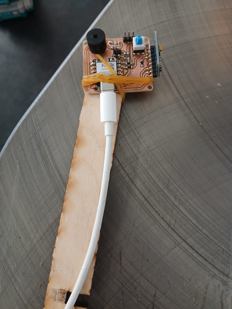
My goal was to create a magic wand that could recognize three symbols: S, O, and X. Instead of pressing buttons, the user simply waves the wand in the air and draws one of these letters. The ESP32-C3 should then recognize the gesture and display the detected character in the Serial Monitor.
This is my Magic Wand.
What is Embedded AI?
"Embedded AI" simply means that a trained machine learning model runs directly on a small microcontroller, instead of on a laptop, phone, or cloud server. There is no internet connection and no computer needed once the system is deployed — the chip itself reads the sensor, does the math, and produces the answer. This is what makes battery-powered, offline, real-time gadgets like this magic wand possible.
For my wand, the whole workflow has four parts. The first two happen once, on my laptop. The last one runs forever, live, directly on the ESP32-C3:
Generate an SVG diagram showing the embedded AI workflow for a gesture-recognition wand: a 4-stage pipeline (1. Collect Data via GestureSampling.ino, 2. Train Model via train_wand.py, 3. Export Weights to model_data.h, 4. Run Inference via WandInference.ino on the ESP32-C3), with a dashed loop-back arrow from inference to data collection labeled "bad results? collect more data", and a caption noting steps 1–2 run once offline while step 4 runs live on the microcontroller.
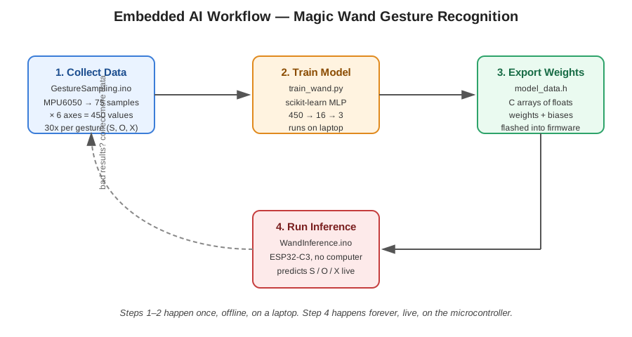
- Collect data — record real motion examples of me drawing S, O, and X (
GestureSampling.ino) - Train a model — turn those examples into a small neural network on my laptop (
train_wand.py) - Export the weights — save the trained network as C code the microcontroller can read (
model_data.h) - Run inference — the ESP32-C3 uses those weights to recognize gestures live, with no computer attached (
WandInference.ino)
The hardware: Hrach's board
Rather than designing a new board just for this experiment, I reused the board Hrach designed and produced during his final project's production week, since it already had exactly the sensor I needed for this experiment.
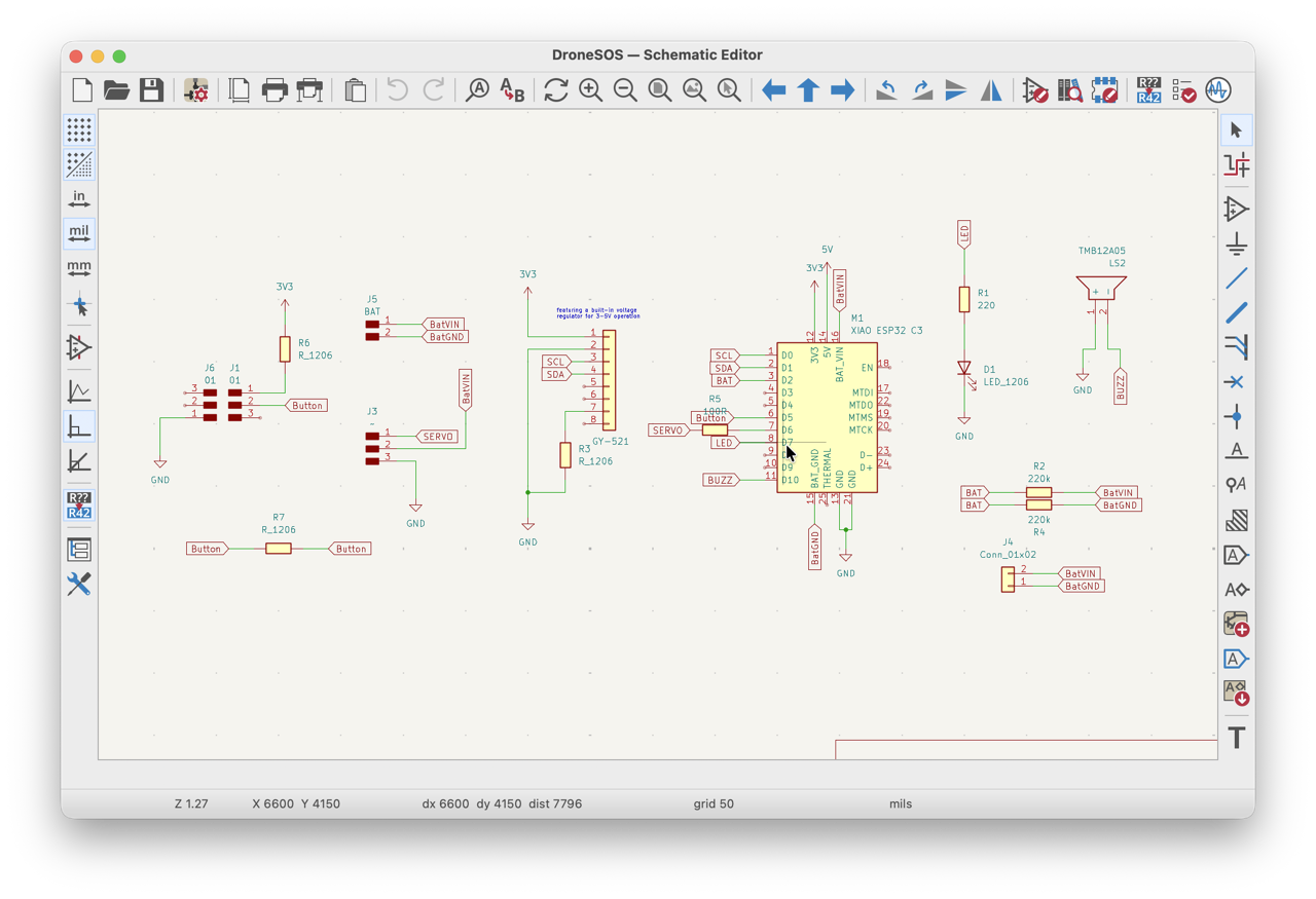
Here is the board and the main components I used from it:
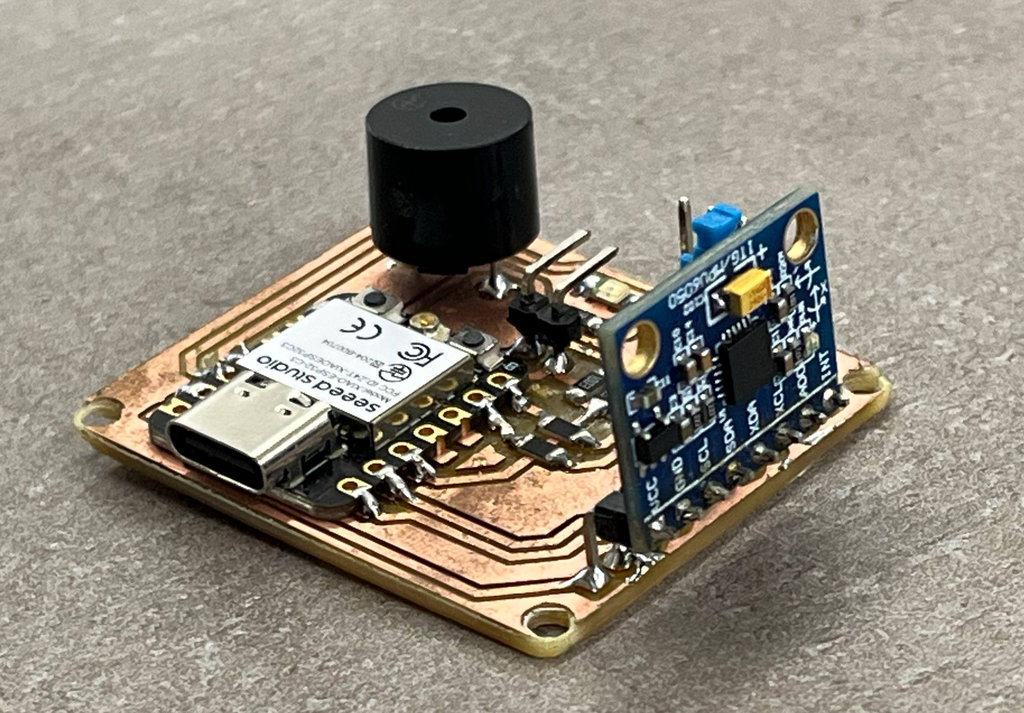
- ESP32-C3: the microcontroller that runs both the Arduino sketches — it samples the sensor and, later, runs the neural network math.
- MPU6050: a 6-axis IMU (3-axis accelerometer + 3-axis gyroscope) connected over I²C. This is the sensor that "feels" the wand moving through the air.
- Buzzer: gives an audible cue for when to start drawing the gesture, and a confirmation beep once a gesture has been recognized.
- USB / power connector: used to flash the firmware and power the board while testing.
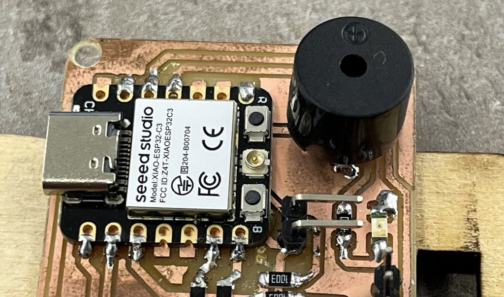
And here is the schematic of the board, showing how the MPU6050, buzzer, and ESP32-C3 are wired together:
Full design files and production details for this board are documented on Hrach's Input Devices page, since he is the one who designed and milled/soldered it.
How the recognition actually works: forward propagation
Before showing any code, it's worth explaining what the ESP32-C3 is actually doing when it "recognizes" a gesture, because this is the core idea the rest of the section builds toward.
A trained neural network is really just two things: a set of numbers (weights and biases) and a fixed sequence of arithmetic that uses those numbers. Running the network on new sensor data is called forward propagation — the data flows forward through the network, layer by layer, until a prediction comes out the other end.
Generate an SVG diagram of the neural network forward-propagation used in WandInference.ino: an input layer of 450 values (75 IMU samples × 6 axes), a hidden layer of 16 neurons with ReLU activation (h = max(0, W1·x + b1)), and an output layer of 3 scores labeled S, O, X (y = W2·h + b2), connected with weighted edges, ending in an argmax box that picks the highest-scoring letter. Include a caption noting the diagram can't run without the trained weights in model_data.h.
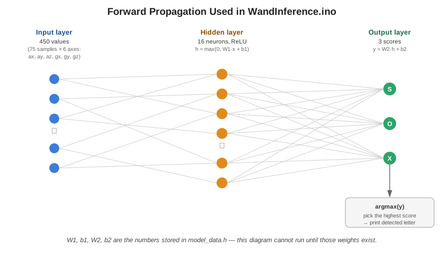
For my wand, forward propagation happens in three steps every time a gesture is drawn:
- Input layer (450 values): the MPU6050 is sampled 75 times over 1.5 seconds, 6 values per sample (ax, ay, az, gx, gy, gz), giving 450 numbers that describe the motion of the drawn letter.
- Hidden layer (16 neurons): each of the 16 hidden neurons computes a weighted sum of all 450 inputs, adds a bias, and passes the result through a ReLU activation (
max(0, x)), which keeps only positive signals and zeroes out the rest. - Output layer (3 scores): the 16 hidden values are combined again into 3 raw scores, one per gesture (S, O, X). The gesture with the highest score is the prediction — this is called
argmax.
This entire calculation is just multiplications, additions, and one comparison — nothing the ESP32-C3 can't handle instantly, and nothing that needs TensorFlow Lite or any ML library. But none of this math means anything without the actual weight values — and those can only come from training on real examples of my own hand movements. That's why the next two sections (data collection, then training) have to happen before the inference code can work at all.
Step 1 — Collecting the training dataset
The first step was to build my own dataset, since the network needs real examples of my own wand movements to learn from — a generic dataset wouldn't match my hand size, wrist motion, or how I hold the wand.
Step by step, this is how one recording was made:
- The board is connected to my laptop over USB, running
GestureSampling.ino, with the Serial Monitor open. - The buzzer gives a short countdown (5 quick beeps), then goes quiet for 2 seconds — my signal to get ready and pick a gesture (S, O, or X) to draw.
- The buzzer starts a continuous quiet tone: this is my "go" signal, and I draw the chosen letter in the air with the wand.
- For exactly 1.5 seconds, the MPU6050 is sampled at 50 Hz, giving 75 readings × 6 axes = 450 numbers.
- Those 450 numbers are printed as one comma-separated line to the Serial Monitor.
- I repeat this 30 times per gesture, copying each line into the matching text file.
I used AI to help generate the first version of this data-collection sketch, then modified and tested it until it correctly matched my hardware and sampling requirements. The final version initializes the MPU6050, samples six-axis motion data at a fixed rate, stores the measurements in a buffer, and streams them through the Serial Monitor for dataset generation.
Generate an Arduino sketch for an ESP32-C3 connected to an MPU6050 over I²C. Sample accelerometer and gyroscope data at 50 Hz for 1.5 seconds, producing 75 samples (450 values total). Use a buzzer to indicate when to start recording, then print all collected values as comma-separated numbers to the Serial Monitor. Repeat until 30 gestures have been collected.
#include <Wire.h>
#include <MPU6050.h>

MPU6050 mpu;

// Pins
const int BUZZER_PIN = D10;

// Sampling Settings
const int SAMPLE_RATE_HZ = 50;
const int RECORD_DURATION_MS = 1500; // Increased to 1.5 seconds
const int NUM_SAMPLES = (SAMPLE_RATE_HZ * RECORD_DURATION_MS) / 1000; // 75 samples
const int SAMPLE_INTERVAL_MS = 1000 / SAMPLE_RATE_HZ; // 20ms between samples

// Dataset Settings
const int TOTAL_GESTURES_TO_COLLECT = 30;
int gesturesCollected = 0;

float sampleBuffer[NUM_SAMPLES * 6];

void setup() {
  Serial.begin(115200);
  while (!Serial);

  pinMode(BUZZER_PIN, OUTPUT);
  analogWrite(BUZZER_PIN, 10); // Ensure silence at start

  Wire.begin(D1, D0);

  mpu.initialize();
  if (!mpu.testConnection()) {
    while (1) {
      Serial.println("ERROR: MPU6050 not found.");
      delay(1000);
    }
  }

  // Countdown sequence so you can get ready (5 quick beeps)
  for(int i = 0; i < 5; i++) {
    analogWrite(BUZZER_PIN, 5); // Quiet beep
    delay(100);
    analogWrite(BUZZER_PIN, 0);
    delay(900);
  }
}

void loop() {
  if (gesturesCollected >= TOTAL_GESTURES_TO_COLLECT) {
    Serial.println("\n=========================================");
    Serial.println("COLLECTION COMPLETE! 30/30 GESTURES SAVED.");
    Serial.println("=========================================");

    analogWrite(BUZZER_PIN, 15); delay(100);
    analogWrite(BUZZER_PIN, 0);  delay(50);
    analogWrite(BUZZER_PIN, 15); delay(300);
    analogWrite(BUZZER_PIN, 0);

    while(1);
  }

  analogWrite(BUZZER_PIN, 0);
  delay(2000);

  analogWrite(BUZZER_PIN, 5);

  int sampleCount = 0;
  unsigned long nextSampleTime = millis();

  while (sampleCount < NUM_SAMPLES) {
    if (millis() >= nextSampleTime) {
      int16_t ax, ay, az, gx, gy, gz;
      mpu.getMotion6(&ax, &ay, &az, &gx, &gy, &gz);

      int idx = sampleCount * 6;
      sampleBuffer[idx + 0] = ax / 16384.0;
      sampleBuffer[idx + 1] = ay / 16384.0;
      sampleBuffer[idx + 2] = az / 16384.0;
      sampleBuffer[idx + 3] = gx / 131.0;
      sampleBuffer[idx + 4] = gy / 131.0;
      sampleBuffer[idx + 5] = gz / 131.0;

      sampleCount++;
      nextSampleTime += SAMPLE_INTERVAL_MS;
    }
  }

  analogWrite(BUZZER_PIN, 0);

  for (int i = 0; i < NUM_SAMPLES * 6; i++) {
    Serial.print(sampleBuffer[i], 4);
    if (i < (NUM_SAMPLES * 6) - 1) Serial.print(",");
  }
  Serial.println();

  gesturesCollected++;
}
To make data collection easier, the board uses the buzzer to provide timing cues. After a short preparation delay, the buzzer starts beeping and I draw the desired letter in the air. Once the recording is complete, all 450 values are transmitted through the Serial Monitor. The process is repeated until 30 recordings have been collected for each gesture.
I organized the collected data using a Python helper script (train_wand.py, described below also handles this step). While the Arduino was streaming sensor values over the serial port, I performed the three gestures (S, O, and X) multiple times and saved the recordings into three separate dataset files:
S_data.txtO_data.txtX_data.txt
In this video I am generating the dataset for letter "O".
These files became the training dataset for the gesture recognition model.

Step 2 — Training the model on my own data
After collecting the datasets, I trained a small neural network using the Python script train_wand.py. The trained weights and biases were automatically exported into a header file called model_data.h.
AI helped generate the first version of the training script, while I adjusted the dataset loading, neural network architecture, and export format so the trained model could be embedded directly into the ESP32 firmware.
Generate a Python script that loads three gesture datasets (S, O and X), trains a small neural network using scikit-learn, evaluates the model, and exports all weights and biases into a C/C++ header file called
model_data.h so it can be used directly inside an Arduino project.
import numpy as np
from sklearn.neural_network import MLPClassifier
from sklearn.model_selection import train_test_split

# 1. Load the data files
print("Loading gesture data...")
try:
    s_data = np.loadtxt('S_data.txt', delimiter=',')
    o_data = np.loadtxt('O_data.txt', delimiter=',')
    x_data = np.loadtxt('X_data.txt', delimiter=',')
except Exception as e:
    print(f"Error loading files: {e}")
    print("Make sure S_data.txt, O_data.txt, and X_data.txt are in this folder.")
    exit()

# 2. Combine data and create matching labels
# Label mapping: 0 = 'S', 1 = 'O', 2 = 'X'
X = np.vstack([s_data, o_data, x_data])
y = np.concatenate([
    np.zeros(len(s_data)),
    np.ones(len(o_data)),
    np.ones(len(x_data)) * 2
])

print(f"Dataset loaded. Total examples: {X.shape[0]} (Features per example: {X.shape[1]})")

# 3. Quick validation split to check performance
X_train, X_test, y_train, y_test = train_test_split(X, y, test_size=0.2, random_state=42)

clf = MLPClassifier(
    hidden_layer_sizes=(16,),
    activation='relu',
    max_iter=3000,
    random_state=42
)

print("Training the neural network...")
clf.fit(X_train, y_train)

train_acc = clf.score(X_train, y_train) * 100
test_acc = clf.score(X_test, y_test) * 100
print(f"Training Accuracy: {train_acc:.2f}%")
print(f"Validation Test Accuracy: {test_acc:.2f}%")

# 4. Retrain on 100% of the data for maximum deployment accuracy
print("Optimizing final weights on complete dataset...")
clf.fit(X, y)

# 5. Extract weights and biases
hidden_weights = clf.coefs_[0].T
hidden_biases = clf.intercepts_[0]
output_weights = clf.coefs_[1].T
output_biases = clf.intercepts_[1]

# 6. Generate the C++ Header File
header_filename = "model_data.h"
print(f"Generating {header_filename} for your Arduino sketch...")

with open(header_filename, "w") as f:
    f.write("// Automatically generated Neural Network Weights\n")
    f.write("// Labels: 0 = 'S', 1 = 'O', 2 = 'X'\n\n")
    f.write("#ifndef MODEL_DATA_H\n#define MODEL_DATA_H\n\n")

    f.write(f"const int NUM_INPUTS = {X.shape[1]};\n")
    f.write("const int NUM_HIDDEN = 16;\n")
    f.write("const int NUM_OUTPUTS = 3;\n\n")

    f.write(f"const float hidden_weights[16][450] = {{\n")
    for row in hidden_weights:
        f.write("    {" + ", ".join([f"{v:.6f}f" for v in row]) + "},\n")
    f.write("};\n\n")

    f.write("const float hidden_biases[16] = {\n    ")
    f.write(", ".join([f"{v:.6f}f" for v in hidden_biases]))
    f.write("\n};\n\n")

    f.write(f"const float output_weights[3][16] = {{\n")
    for row in output_weights:
        f.write("    {" + ", ".join([f"{v:.6f}f" for v in row]) + "},\n")
    f.write("};\n\n")

    f.write("const float output_biases[3] = {\n    ")
    f.write(", ".join([f"{v:.6f}f" for v in output_biases]))
    f.write("\n};\n\n")

    f.write("#endif\n")

print("Success! 'model_data.h' is ready to use.")
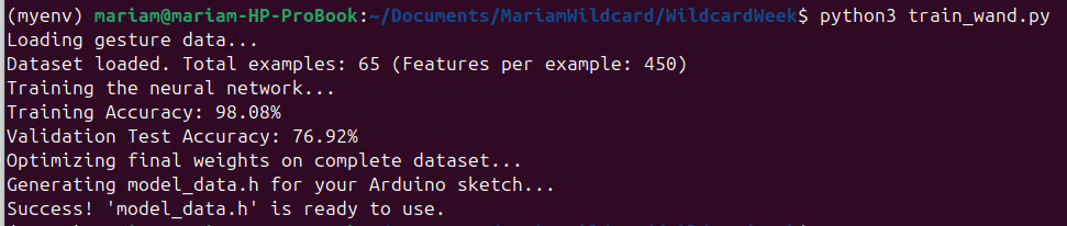
The script trains the neural network, evaluates its accuracy, retrains using the complete dataset, and automatically generates the model_data.h file containing all network parameters required by the ESP32.
Here is a photo of the actual training run on my hardware setup — the board still connected, terminal running train_wand.py, and the accuracy numbers printing out:
The generated model_data.h stores everything the ESP32 needs to run the network on its own:
- 450 input neurons
- 16 hidden neurons
- 3 output classes (S, O, and X)
This allows the microcontroller to perform the entire inference locally without requiring a computer or an internet connection. A short excerpt of the generated file is below (the full file is included in the downloads section, since it is mostly a long list of numbers):
// Automatically generated Neural Network Weights
// Labels: 0 = 'S', 1 = 'O', 2 = 'X'

#ifndef MODEL_DATA_H
#define MODEL_DATA_H

const int NUM_INPUTS = 450;
const int NUM_HIDDEN = 16;
const int NUM_OUTPUTS = 3;

const float hidden_weights[16][450] = {
    { /* ... 450 float values ... */ },
    { /* ... 450 float values ... */ },
    // ... 16 rows total, one per hidden neuron
};

const float hidden_biases[16] = { /* 16 float values */ };

const float output_weights[3][16] = {
    { /* ... 16 float values ... */ }, // score for 'S'
    { /* ... 16 float values ... */ }, // score for 'O'
    { /* ... 16 float values ... */ }, // score for 'X'
};

const float output_biases[3] = { /* 3 float values */ };

#endif
// Full file (with all real numbers) is in the downloads section below.
Step 3 — Running inference on the ESP32
The final Arduino program, WandInference.ino, combines sensor acquisition with the embedded neural network described earlier. This is the code that actually implements the forward-propagation math explained above, using the real weight values from model_data.h.
I again used AI to generate the initial structure, then adapted it to my trained model and hardware configuration. The sketch continuously collects motion data, feeds it into the embedded neural network, and predicts which gesture was performed.
Generate Arduino code for an ESP32-C3 that loads a neural network from
model_data.h, reads 450 motion values from an MPU6050, performs feed-forward inference using one hidden layer with ReLU activation, predicts one of three classes (S, O or X), prints the detected symbol to the Serial Monitor, and plays a short buzzer sound after recognition.
#include <Wire.h>
#include <MPU6050.h>
#include "model_data.h" // Your custom neural network weights!

MPU6050 mpu;

const int BUZZER_PIN = D10;

const int SAMPLE_RATE_HZ = 50;
const int RECORD_DURATION_MS = 1500;
const int NUM_SAMPLES = (SAMPLE_RATE_HZ * RECORD_DURATION_MS) / 1000;
const int SAMPLE_INTERVAL_MS = 1000 / SAMPLE_RATE_HZ;

float sampleBuffer[450];

const char labels[3] = {'S', 'O', 'X'};

void setup() {
  Serial.begin(115200);
  while (!Serial);

  pinMode(BUZZER_PIN, OUTPUT);
  analogWrite(BUZZER_PIN, 0);

  Wire.begin(D1, D0);

  mpu.initialize();
  if (!mpu.testConnection()) {
    while (1) {
      Serial.println("ERROR: MPU6050 not found.");
      delay(1000);
    }
  }

  Serial.println("\n=========================================");
  Serial.println("WAND LIVE GESTURE RECOGNITION READY");
  Serial.println("Wait for silence -> Hear BEEP -> Draw S, O, or X");
  Serial.println("=========================================");
  delay(2000);
}

void loop() {
  Serial.println("\nReady... Prepare your hand.");
  delay(2000);

  Serial.println("DRAW NOW!");
  analogWrite(BUZZER_PIN, 15);

  int sampleCount = 0;
  unsigned long nextSampleTime = millis();

  while (sampleCount < NUM_SAMPLES) {
    if (millis() >= nextSampleTime) {
      int16_t ax, ay, az, gx, gy, gz;
      mpu.getMotion6(&ax, &ay, &az, &gx, &gy, &gz);

      int idx = sampleCount * 6;
      sampleBuffer[idx + 0] = ax / 16384.0;
      sampleBuffer[idx + 1] = ay / 16384.0;
      sampleBuffer[idx + 2] = az / 16384.0;
      sampleBuffer[idx + 3] = gx / 131.0;
      sampleBuffer[idx + 4] = gy / 131.0;
      sampleBuffer[idx + 5] = gz / 131.0;

      sampleCount++;
      nextSampleTime += SAMPLE_INTERVAL_MS;
    }
  }

  analogWrite(BUZZER_PIN, 0);
  Serial.println("Processing gesture...");

  // Hidden layer (ReLU)
  float hidden_outputs[16];
  for (int i = 0; i < NUM_HIDDEN; i++) {
    float activation = hidden_biases[i];
    for (int j = 0; j < NUM_INPUTS; j++) {
      activation += sampleBuffer[j] * hidden_weights[i][j];
    }
    hidden_outputs[i] = (activation > 0.0f) ? activation : 0.0f;
  }

  // Output layer
  float final_outputs[3];
  for (int i = 0; i < NUM_OUTPUTS; i++) {
    float activation = output_biases[i];
    for (int j = 0; j < NUM_HIDDEN; j++) {
      activation += hidden_outputs[j] * output_weights[i][j];
    }
    final_outputs[i] = activation;
  }

  // Argmax
  int predicted_class = 0;
  float max_score = final_outputs[0];
  for (int i = 1; i < NUM_OUTPUTS; i++) {
    if (final_outputs[i] > max_score) {
      max_score = final_outputs[i];
      predicted_class = i;
    }
  }

  Serial.print(">>> DETECTED SYMBOL: ");
  Serial.print(labels[predicted_class]);
  Serial.print(" <<< (Score: ");
  Serial.print(max_score);
  Serial.println(")");

  analogWrite(BUZZER_PIN, 15); delay(60);
  analogWrite(BUZZER_PIN, 0);  delay(40);
  analogWrite(BUZZER_PIN, 15); delay(60);
  analogWrite(BUZZER_PIN, 0);

  delay(1000);
}
I modified the generated code to match my sensor calibration, sampling configuration, buzzer feedback, and gesture timing. I also verified that the inference pipeline used exactly the same preprocessing and input dimensions as the training script to ensure reliable predictions.
Every time the user draws a letter:
- The MPU6050 records motion data for 1.5 seconds.
- The collected sensor values are stored in a 450-element input buffer.
- The embedded neural network calculates the hidden layer using the ReLU activation function.
- The output layer computes three scores corresponding to the letters S, O, and X.
- The class with the highest score is selected, and the detected letter is printed in the Serial Monitor.
- Finally, the buzzer emits a short double beep to indicate that the gesture has been successfully recognized.
This experiment allowed me to explore how machine learning models can be deployed directly on a microcontroller. Even with a relatively small neural network, the ESP32-C3 was able to classify hand gestures in real time without using TensorFlow Lite or any external inference library. It demonstrated that lightweight embedded AI can be implemented efficiently using only Arduino code and a trained set of neural network weights.
After integrating all three stages — data collection, model training, and embedded inference — I successfully created a simple gesture recognition system running entirely on the ESP32-C3. The microcontroller is capable of recognizing the letters S, O, and X in real time without requiring a computer or an external machine learning framework. This experiment helped me better understand how embedded AI can be implemented on resource-constrained microcontrollers and demonstrated the complete workflow from dataset creation to deployment.
All files related to this experiment (both Arduino sketches, the training script, the raw datasets, and the generated model_data.h) are bundled together in the downloads section at the end of this page, as MariamWildCard-EmbeddedAI.zip, so anyone can reproduce the full pipeline from scratch.
This week I learned a lot about composites, biomaterials, and how material behavior can completely change a final result. I learned how to combine digital design with physical fabrication, how to prepare and modify biomaterials, and how reinforcement materials such as fiberglass and linen affect strength and shape.
I also learned that sometimes the first result is not the final result 😄 Small changes like material thickness, adding Xanthan Gum, or changing fabric type can create very different outcomes.
One thing I really enjoyed this week was seeing my own car design slowly become a real physical object instead of only existing on my computer screen.
- Car And Wheels - CarAndWheels.zip
- O_S_X_Datasets - O_S_X_Datasets.zip
AI prompt:
“And Generate image when she fineshed Week 17”