Week 16
AI prompt:
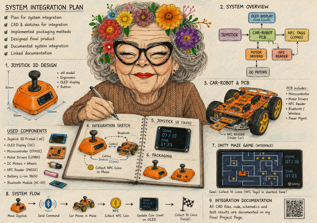
"A cozy Fab Academy workshop scene with a smiling granny engineer finishing her "System Integration" week project: a purple 3D-printed joystick with OLED display controlling a PCB car-robot in a Unity maze game. The robot collects NFC coin tags with a timer system, surrounded by CAD sketches, wiring diagrams, Fab Academy notes, electronics, and colorful technical drawings in a warm hand-painted illustration style."
System Integration
Joystick controller — system integration
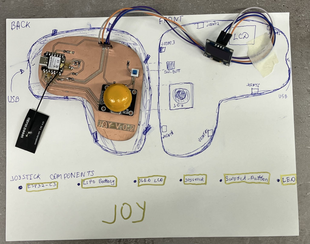
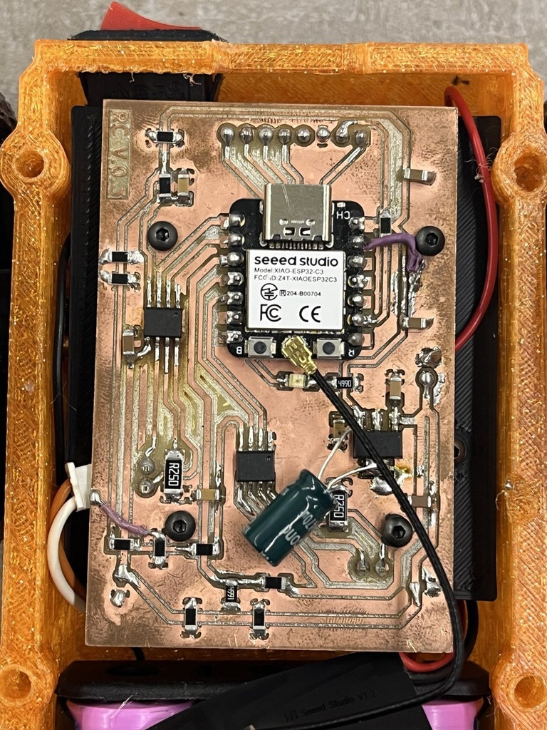
The joystick is the primary input device for the NFC maze game. It integrates a custom ESP32-C3 PCB inside a 3D-printed 2-part PETG enclosure, with a WiFi Conection with joystick, OLED display, wireless module, and LiPo battery with USB-C charging.
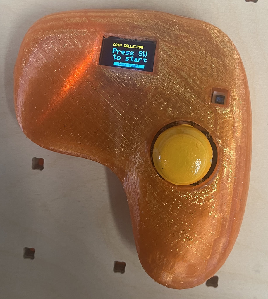
The OLED screen shows the coin count and timer received wirelessly from the car-robot, so the player can see their score without looking at the physical maze board. The Unity 3D maze game ( Week 15 ) also reads the joystick over USB serial for digital testing.
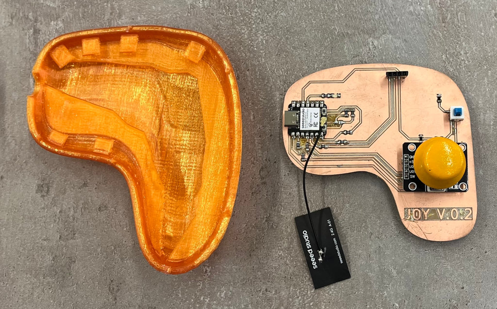
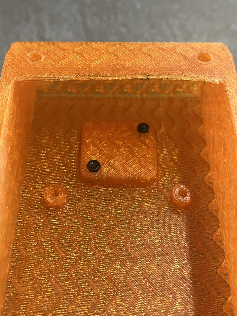
After printing the joystick using PETG filament, it was ready for assembly.
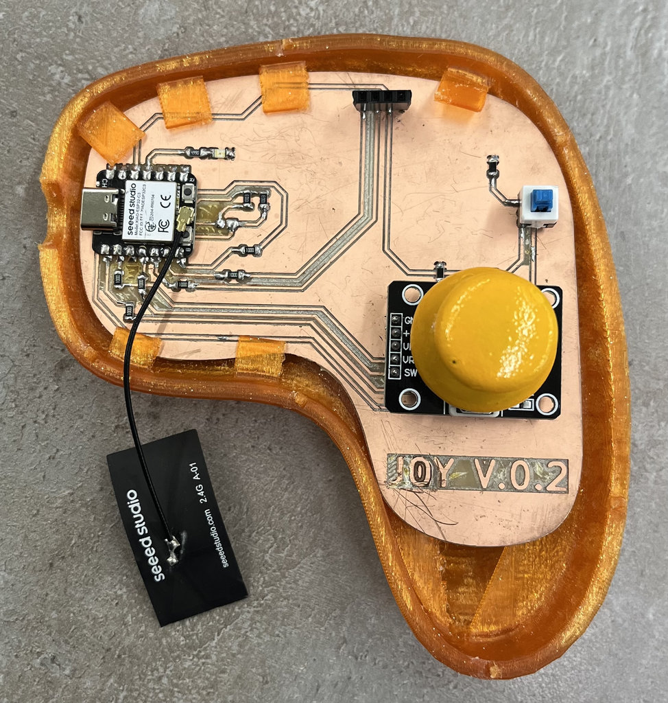
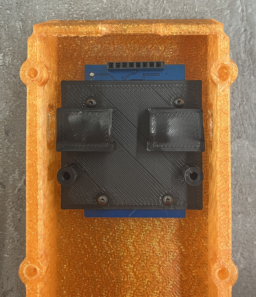
Since I had also imported the 3D model of the PCB into Blender, I had already designed the exact space for it. The six clips on the top and the lower half panel securely hold the PCB in place.
Next, I replaced the straight pin headers with angled pin headers so they would not interfere with the top cover when closing the case.
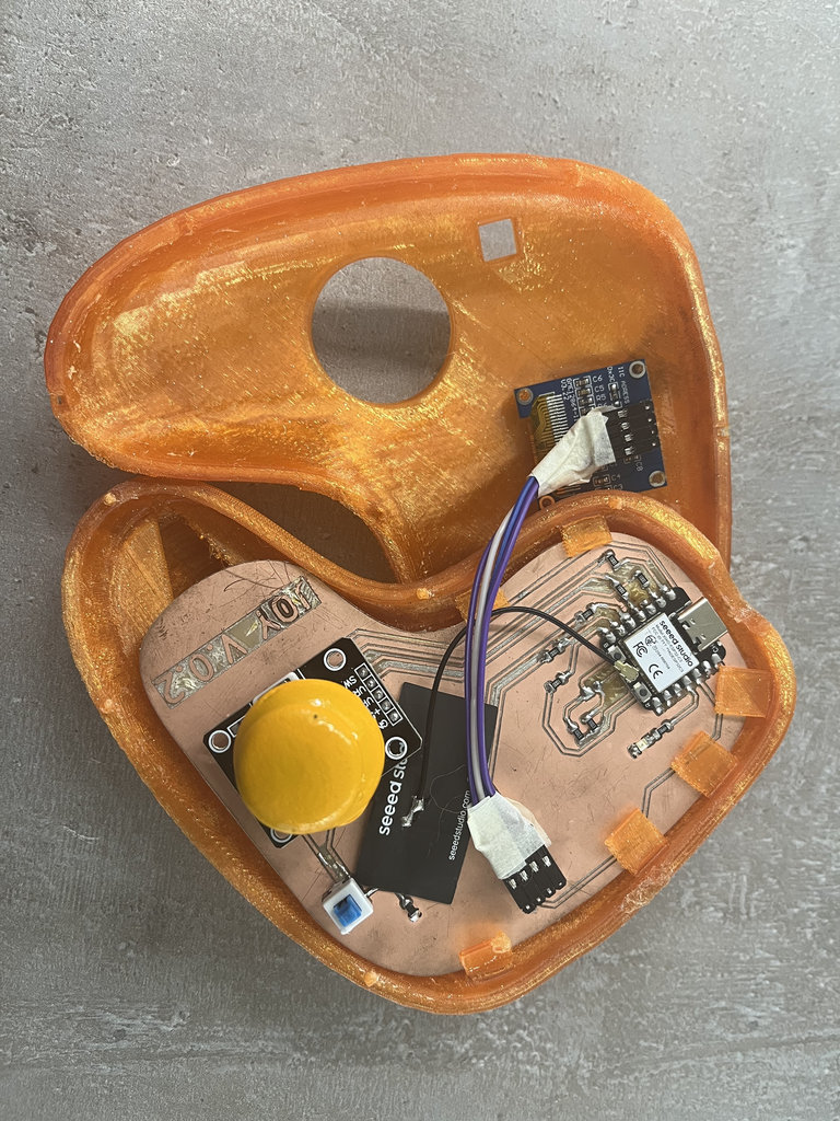
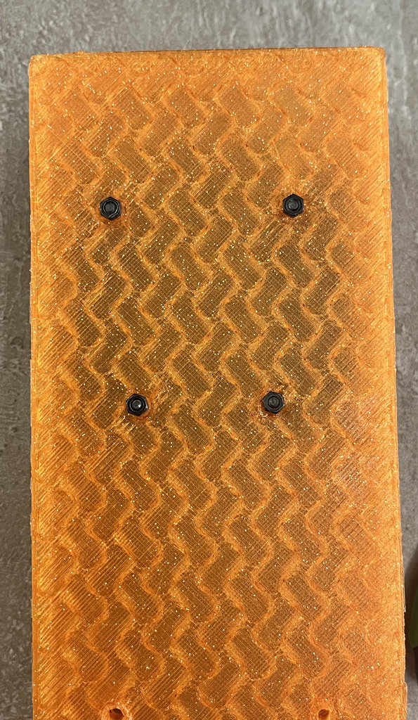
Then I connected everything with wires and closed the case. The small joints were very convenient and were enough to keep everything firmly assembled.
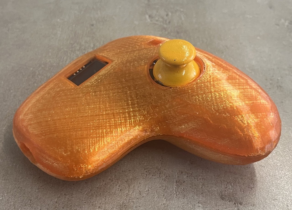
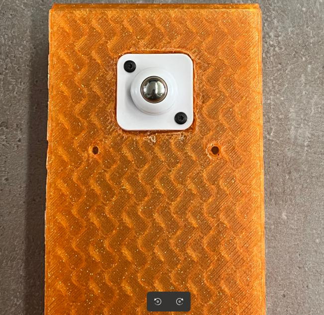
Here is the joystick from the side and the front.
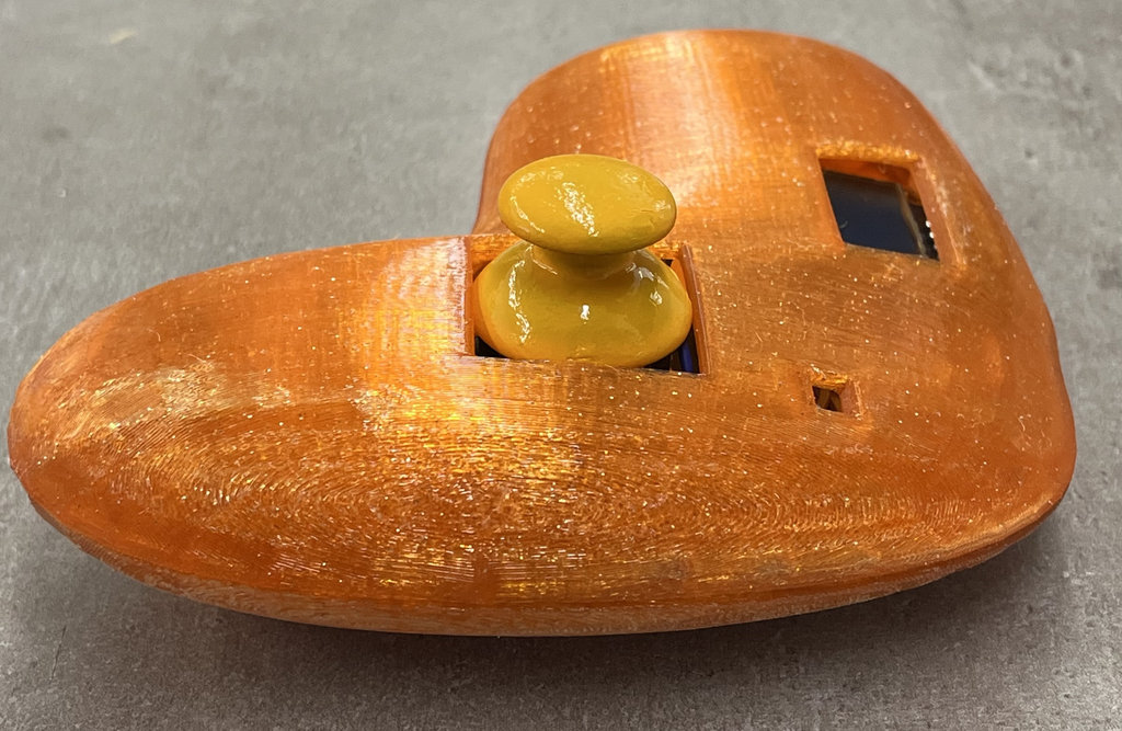
It would have been possible to 3D print a proper button for the switch button, but I preferred to use my ring to turn it on and off. 😄😄
Car-robot — system integration
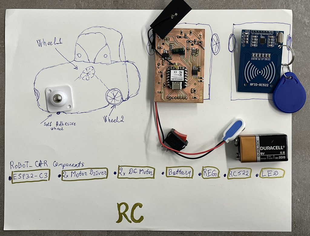
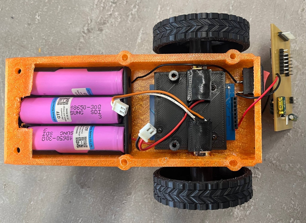
The car-robot is a 2-wheel and one Self adhesive caster wheels drive MDF chassis with a custom ESP32-C3 PCB. It receives wireless commands from the joystick via WiFi, drives 2 DC motors through 2× A4953 Motor Drivers, and detects NFC tags embedded in the maze floor using an RC522 reader at 13.56 MHz.
Each time the robot drives over one of the 10 NFC coin tags, it increments the coin counter and sends the updated count back to the joystick over the RF link so the OLED display updates instantly.
You can find the initial design and modeling details of the robot car in Week 17. I combined the work from the last two weeks, so the documentation is slightly out of chronological order. 😄😄
Now let's move on to the robot car assembly process.s
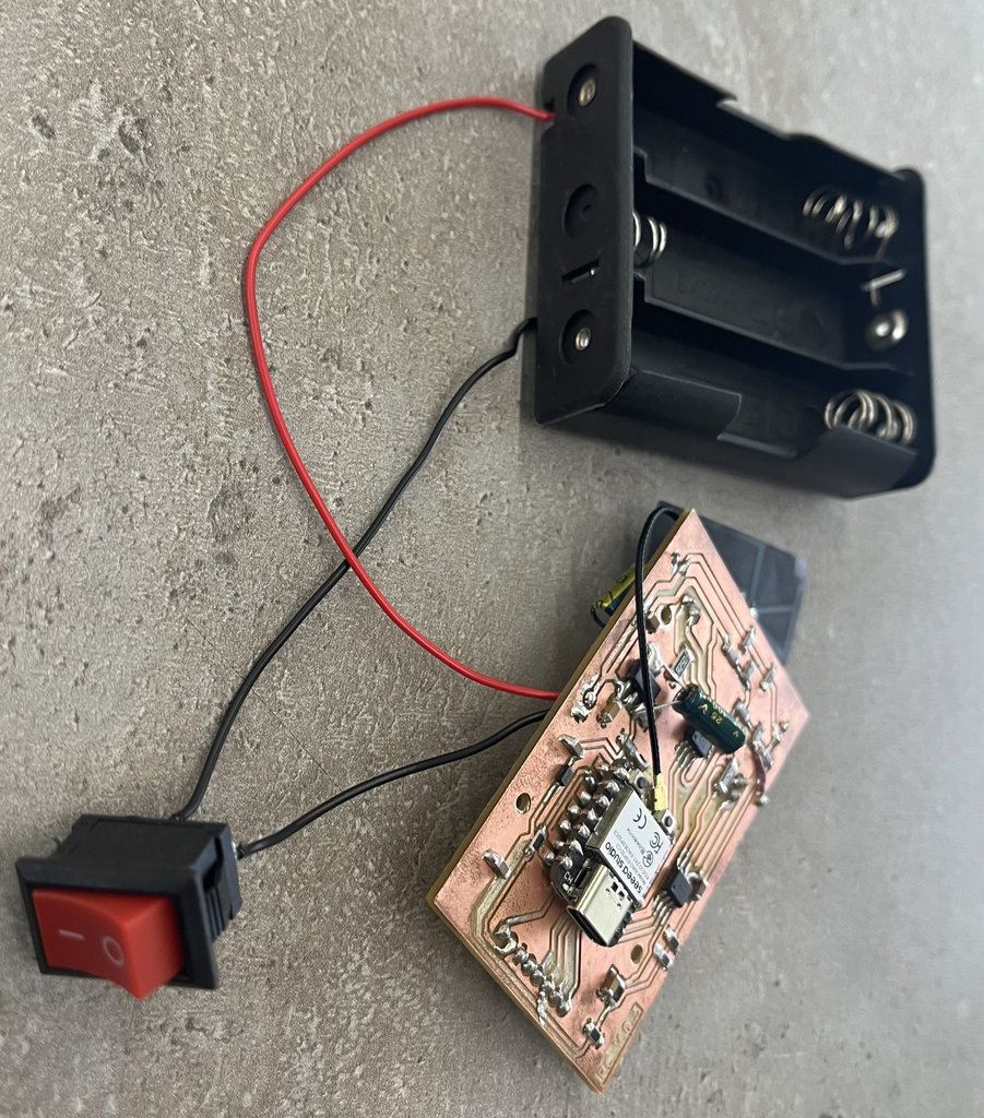
First, I connected the PCB to the battery case together with the power button.
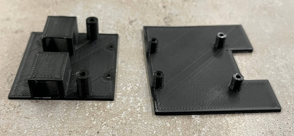
I should also mention that I designed and printed mounting panels for both the PCB and the NFC reader so they could be securely attached inside the main body of the car.
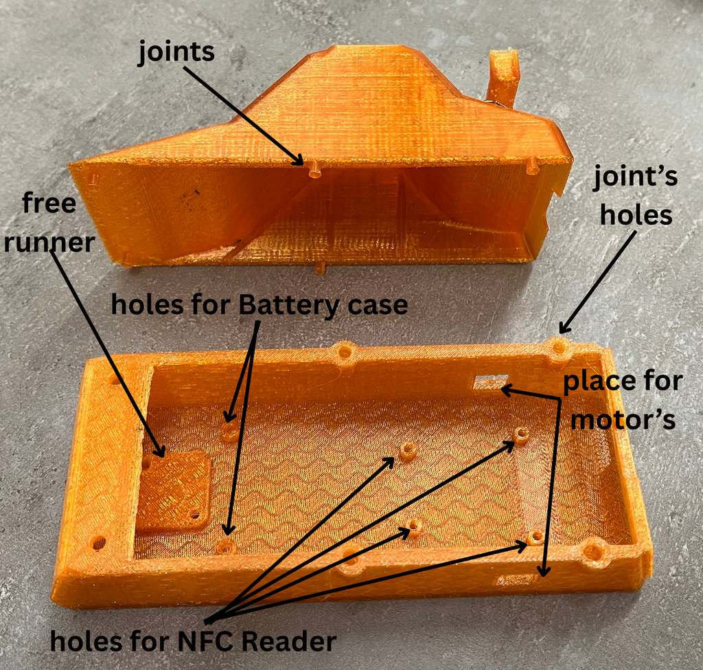
In the image below, I have marked with arrows what each opening in the car is intended for.
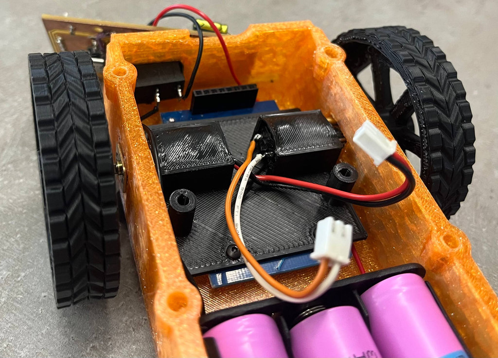
First, I mounted the free runner in its designated position using bolts and nuts.
Next, I mounted the NFC reader together with its dedicated panel, again using bolts and nuts.
For the motors, I designed protective mounting housings. I intentionally modeled them so that the motors fit very tightly inside, preventing any movement later.
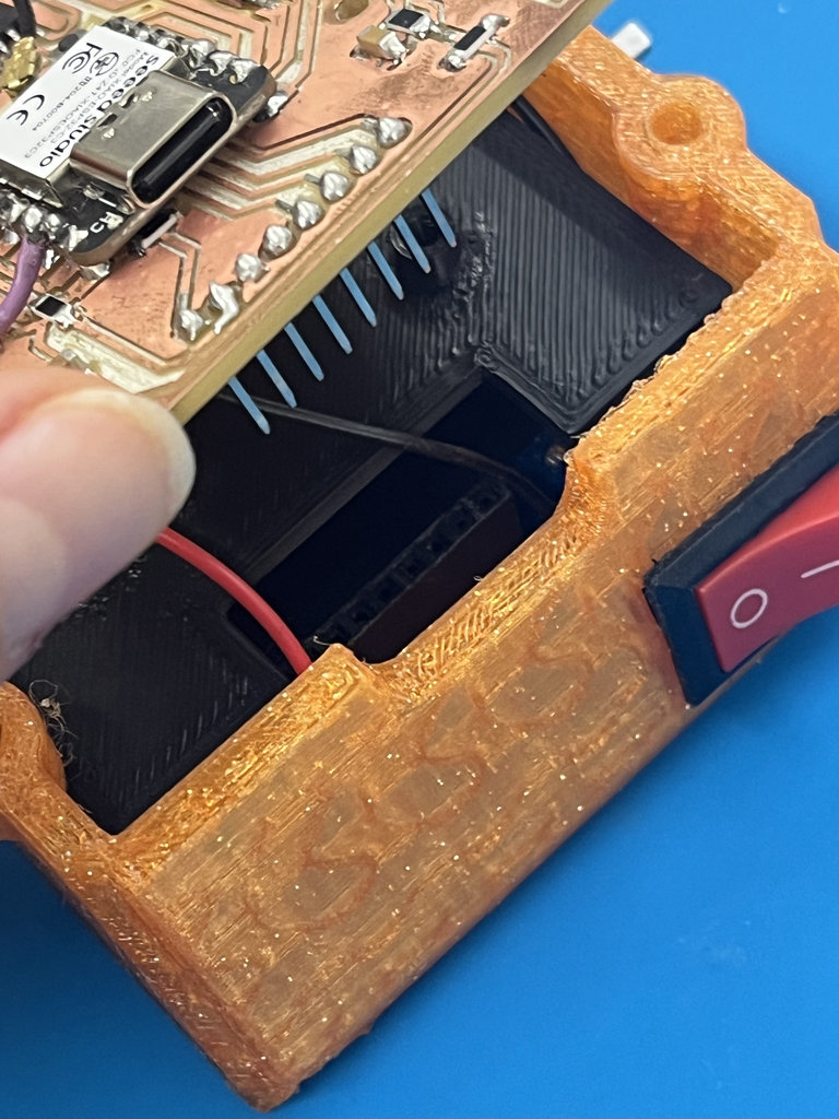
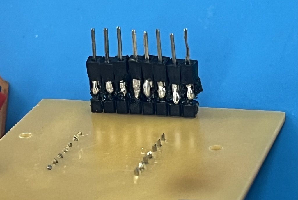
Then I attached the PCB mounting panel to the lower panel, but when I tried to install the PCB, the distance to the NFC reader was not enough because of the pin headers.
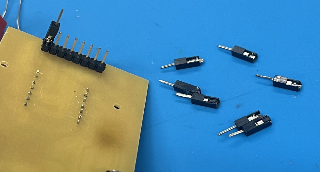
To avoid using long wires everywhere, I decided to take male jumper wires, cut them to the required length so they could reach the NFC reader, and solder them directly onto the PCB pin headers.
Here is my very ugly... but brilliant solution. 😄😄
And finally, the PCB was also mounted onto its panel and connected directly to the NFC reader.
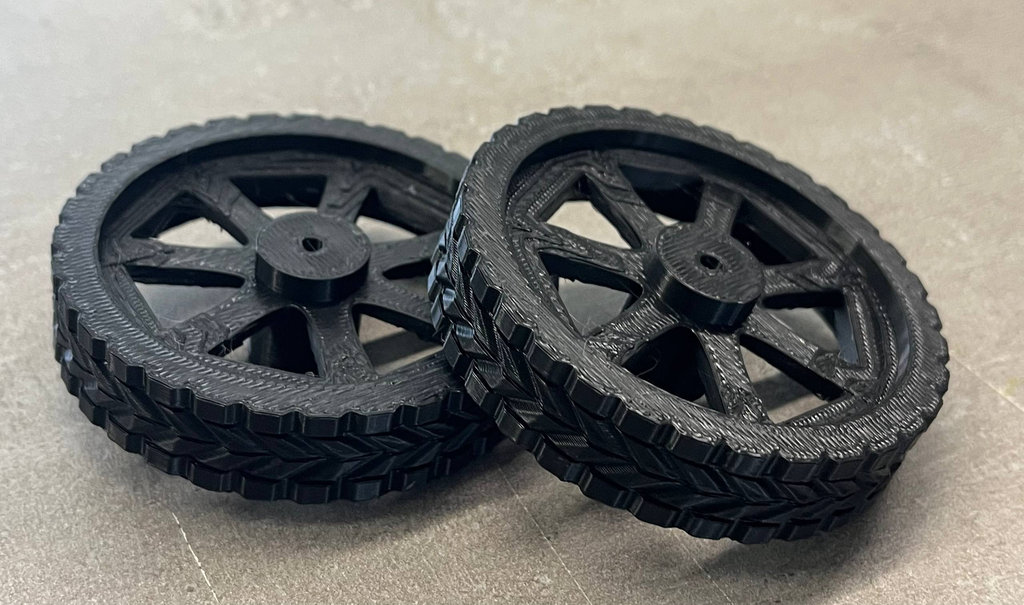
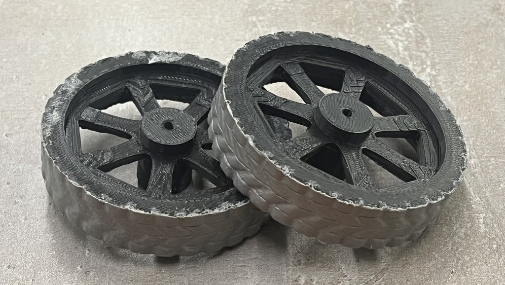
Since I printed the robot wheels using PLA filament, they could easily slip on wood and other smooth surfaces. Because of that, I needed to make them more rubber-like.
However, instead of redesigning only the outer layer of the wheels and printing it with TPU, I decided to buy Leak Repair Spray and coat the wheels with it.
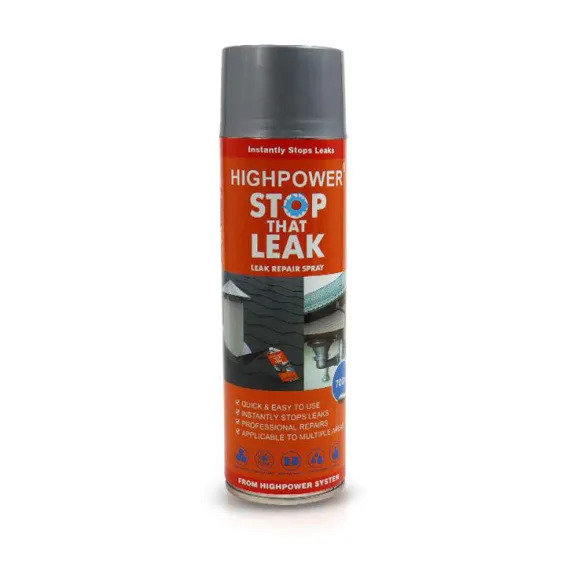
Here are the wheels before and after applying the coating.
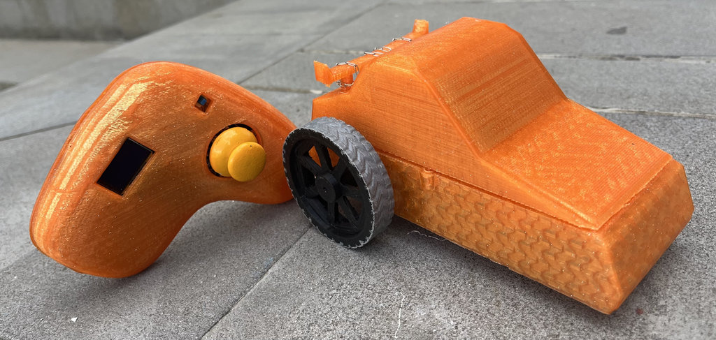
And here are the joystick and the robot car together.
Finally, here is the time-lapse video showing the complete assembly process of the robot car.
Final project timeline
Every weekly assignment contributed a building block toward the final NFC maze game. Click any week to expand its details and deliverables.
This week I brought together all the work from Weeks 1–15 into a single working system. The joystick need to sends wireless commands to the car-robot, the robot navigates the CNC-milled maze and detects NFC coin tags, and the collected coin count is sent back to the joystick OLED display in real time. The Unity interface also mirrors the physical game for digital testing.
The 3D-printed joystick enclosure (2 parts, PLA) gives the controller a finished product feel, with all components cleanly mounted inside on standoffs. The car-robot chassis has the RC522 sensor flush-mounted to the underside so it reads coins reliably as the robot drives over them.

AI prompt:
"And Generate image when she finished Week 16"