
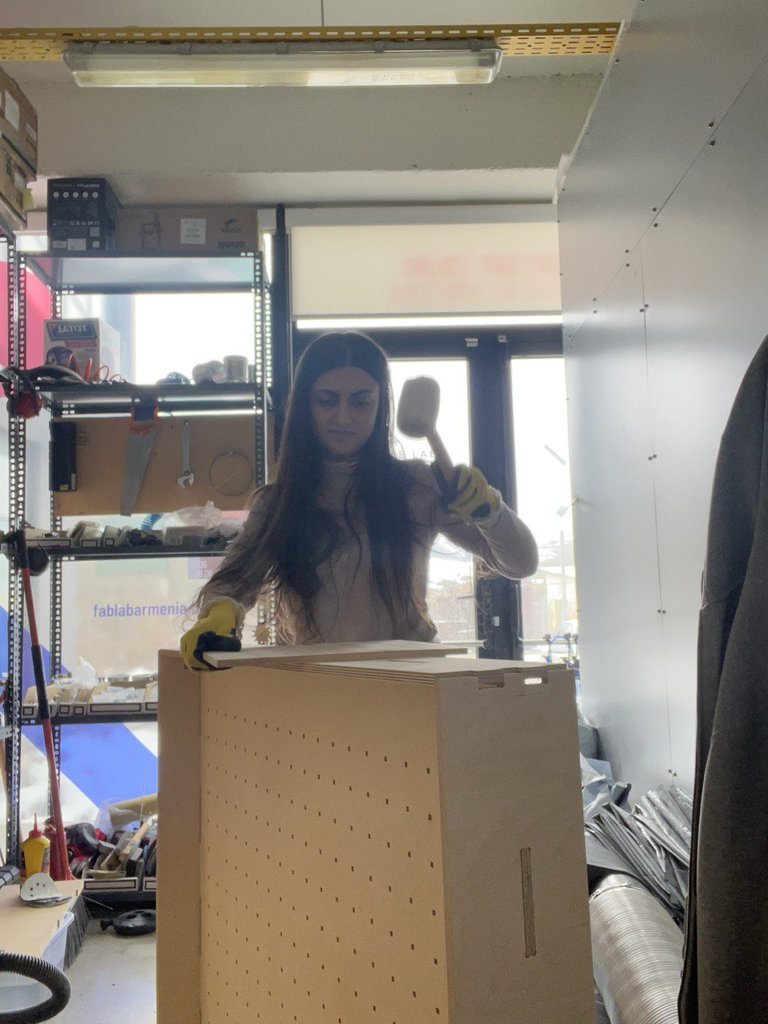
Week 7
AI prompt:
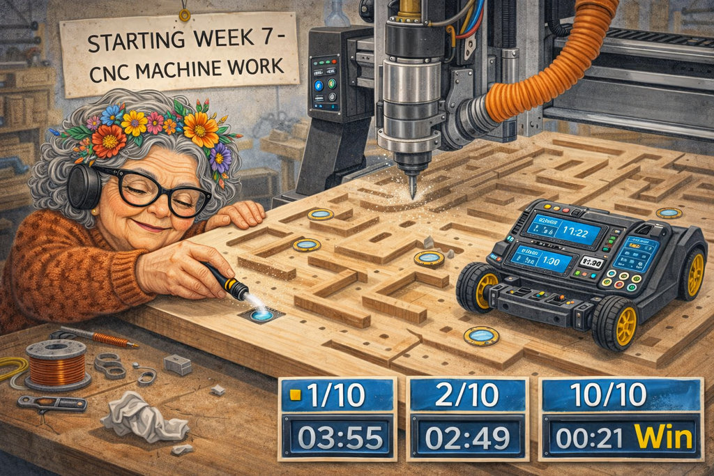
“Now need to generate an image when she started week 7, and she works with cnc machine, cutting her final project game board. It will be 1mx1m square, with labyrinth walls. The board has 10 NFC tags, and a car with nfc reader needs to collect that coins-tags, and when collect one, into lcd print "1/10" on the LCD, after collecting another "2/10" and when collect all 10 coins print "Win" on the LCD. The LCD timer needs to display the time and needs to collect all the coins within that time.”
computer-controlled machining
You can find the full group assignment, including safety training and machine details from both the Dilijan and Gyumri labs, on our group assignment page.
Personal Protective Equipment (PPE) was required at all times: safety glasses, hair tied back, and no loose clothing or jewelry near the spindle.

A fire extinguisher and fire blanket were also kept accessible near the machine at all times, since wood dust is a fire hazard when it accumulates.
For the group assignment, we first discussed and documented the safety rules for using the CNC machine during the computer-controlled machining process. These rules included properly fixing the material to the machine bed, checking the tool and holder before starting, wearing safety equipment, keeping a safe distance during machining, and always being ready to stop the machine in case of emergency. Understanding these safety procedures is essential to prevent accidents and damage to the machine.
Also, I should mention that our CNC machine is a ShopBot PRS5 Alpha, you can find more details about it here.
After documenting the safety rules, we performed a test cutting process to observe how the CNC machine works and to verify that the toolpaths and machine settings were correct.
We decided to include some parts of my individual assignment in the testing process, since they were good examples and also helped me move forward with my own project 😊.
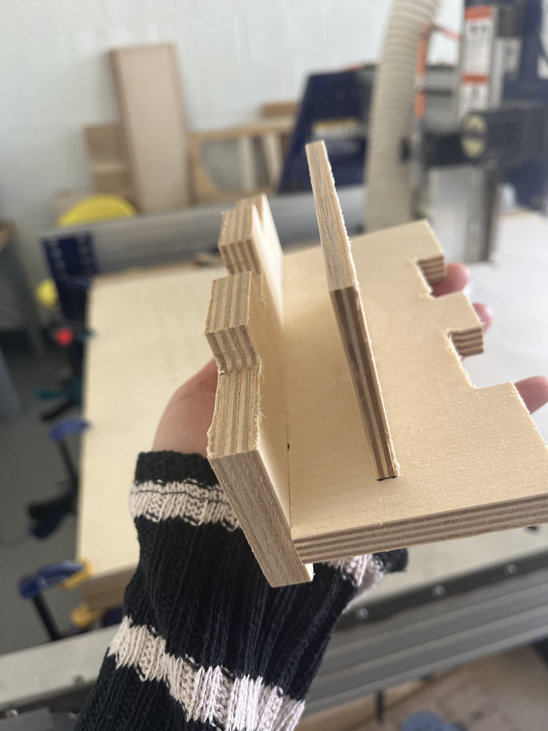
One of the tests included joint connections, to check how the parts fit together. One case tested a tight-fit joint, where the pieces are intentionally difficult to insert, while another tested a self-locking joint, where the parts connect using their shapes without additional adjustments.
All of these tests were cut on 12 mm thick plywood.
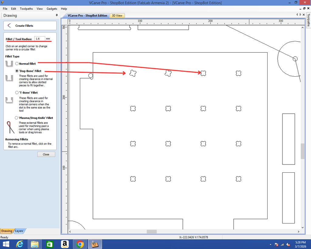
We also performed another test from my individual assignment: creating a grid structure using different types of fillets. One version used a normal fillet, while the other used a dog-bone fillet, which is commonly used in CNC machining to allow square internal corners.
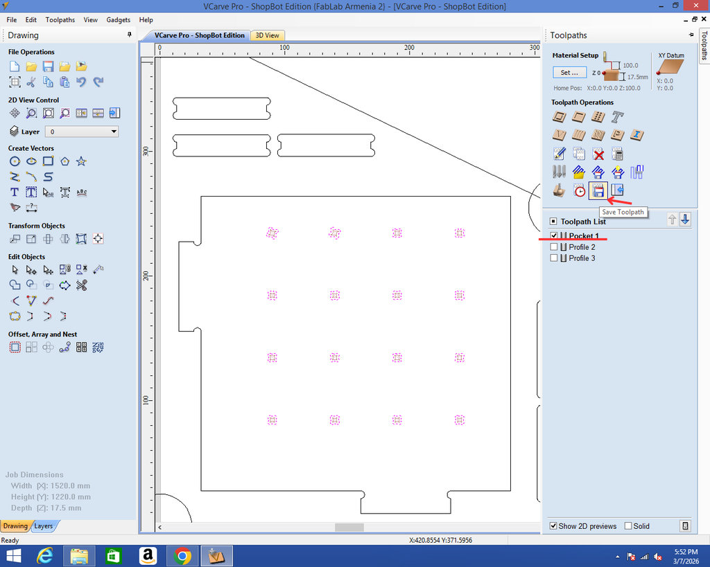
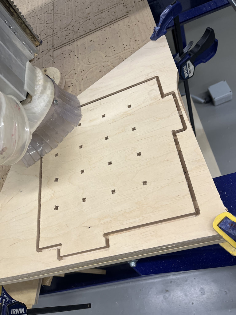
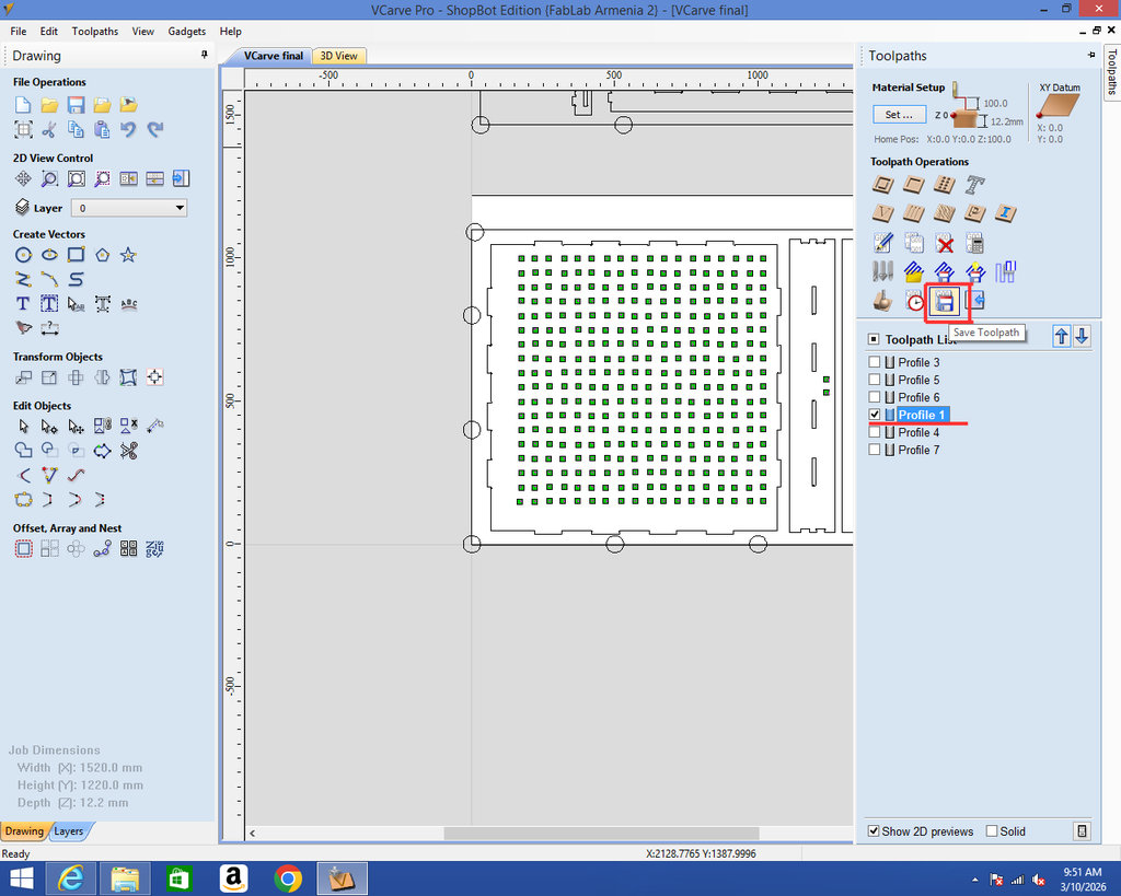
After creating the holes, we select the pocket area where this operation is needed, and then we click Save Toolpath.
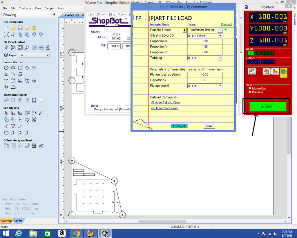
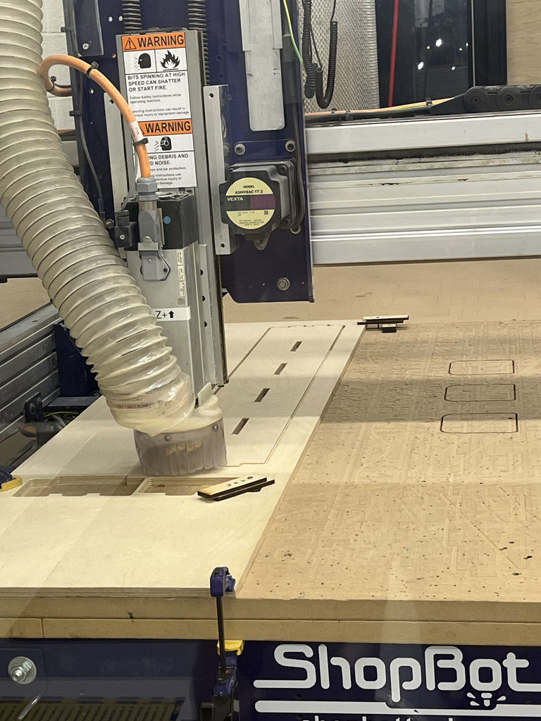
Once everything is ready and after checking safety again, we open the ShopBot software, click Cut Part, select our saved file, and press Start.

Here is an image from the process.
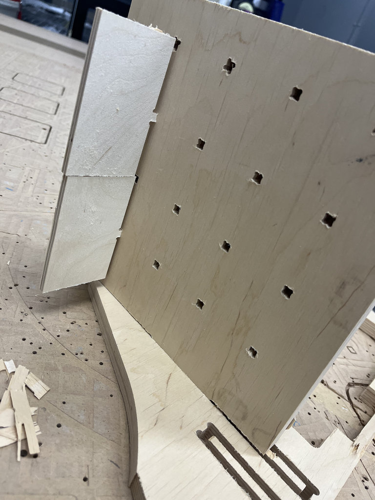
Additionally, we tested the labyrinth walls for the maze, which were cut from 6 mm plywood. This was also a joint test, but for a different material thickness.
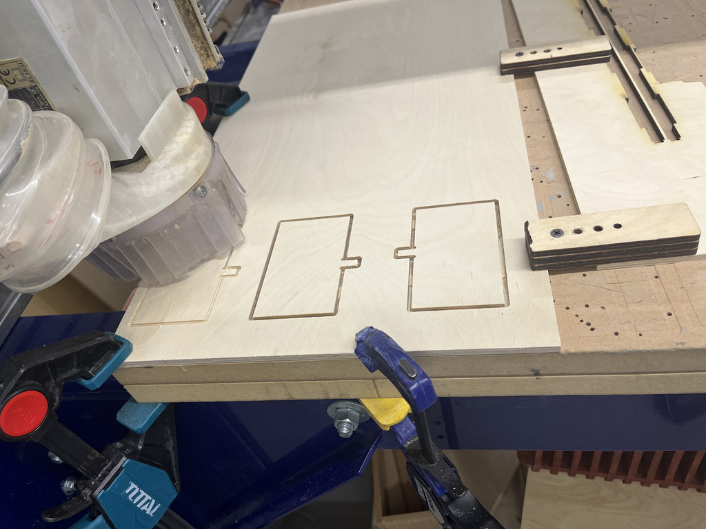
Below are the final results of the tests.
For the individual assignment, I planned to manufacture the game board for my Final Project using a CNC machine.
For this purpose, I separated the parts of the labyrinth that I designed in OpenSCAD. The following components are required:
1. Bottom Base Plate
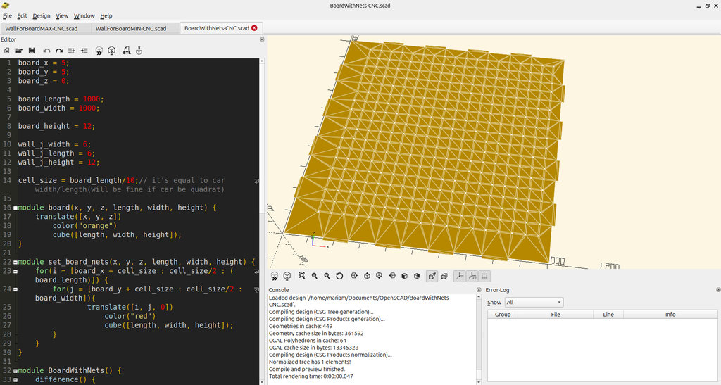
The first part is the bottom section, where the car will drive and where the entire labyrinth will be assembled. From the previous full OpenSCAD code, I separated the floor section with holes, and additionally added side joints to attach the walls.
It should be noted that I will cut this part from a 12 mm thick material, therefore the parameter is defined as: board_height = 12;
Below is the image of this part and the corresponding code.
Before designing the parts in OpenSCAD, I measured the plywood thickness using a caliper. The measured value was approximately 12 mm, so I used this value as the material thickness throughout the design by defining board_height = 12. Since the CNC machine uses a 6 mm end mill, I also designed all slots and joints based on this tool diameter. This parametric approach allows the design to be easily adapted by changing only these variables if another material thickness or cutter diameter is used.
Accounting for machine runout: I couldn't find a published runout spec for our ShopBot PRS5 Alpha, so instead of relying on a datasheet number, we measured it empirically during the group assignment's Test 1: we cut matching square and circle pockets and cutouts (using dogbones and tabs to ensure accurate fit) to see if they'd fit into one another. Checked with a vernier caliper, the pockets came out about 0.4 mm undersized compared to the design — that's the real, tested value for how much our specific machine and bit combination were removing beyond the nominal tool diameter.
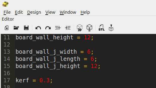
Since that compensation applies symmetrically to both sides of a cut, half the measured discrepancy (~0.2 mm) was my starting point. In practice, after test-fitting joints on the actual machine, 0.3 mm gave a noticeably better, snugger fit, so that's the value I used as kerf in my final OpenSCAD design — applied directly in the joint() module so the physical fit matches what the digital design intends.
Here is where that compensation actually appears in the code:
And all code:
board_x = 5;
board_y = 5;
board_z = 0;
board_length = 1000;
board_width = 1000;
board_height = 12;
wall_j_width = 6;
wall_j_length = 6;
wall_j_height = 12;
cell_size = board_length/10;// it's equal to car width/length(will be fine if car be quadrat)
module board(x, y, z, length, width, height) {
translate([x, y, z])
color("orange")
cube([length, width, height]);
}
module set_board_nets(x, y, z, length, width, height) {
for(i = [board_x + cell_size : cell_size/2 : (board_length)]) {
for(j = [board_y + cell_size : cell_size/2 : board_width]){
translate([i, j, 0])
color("red")
cube([length, width, height]);
}
}
}
module BoardWithNets() {
difference() {
board(board_x, board_y, board_z, board_length, board_width, board_height);
set_board_nets(board_x, board_y, board_z+2, wall_j_width, wall_j_length, wall_j_height);
}
}
module joint(tx, ty, coefficient1, coefficient2, coefficient3) {
translate([tx, ty, 0]) color("black") cube([board_height * coefficient1, board_height * coefficient2, board_height * coefficient3]);
}
projection(cut = false) {
union() {
BoardWithNets();
// Loop through regarding wich count joints I want to set side of my board, If I want to 3 joint need to set loop 1/4, 2/4, 3/4. if I want to 5 joint need to set this loop 1/6, 2/6, 3/6, 4/6, 5/6
for (pos = [1/5, 2/5, 3/5, 4/5]) {
offset = board_length * pos- board_height * 4;
// Bottom & Top sides
joint(board_x + offset, board_y - board_height, 8, 1, 1);
joint(board_x + offset, board_y + board_width, 8, 1, 1);
// Left & Right sides
joint(board_x - board_height, board_y + offset, 1, 8, 1);
joint(board_x + board_length, board_y + offset, 1, 8, 1);
}
}
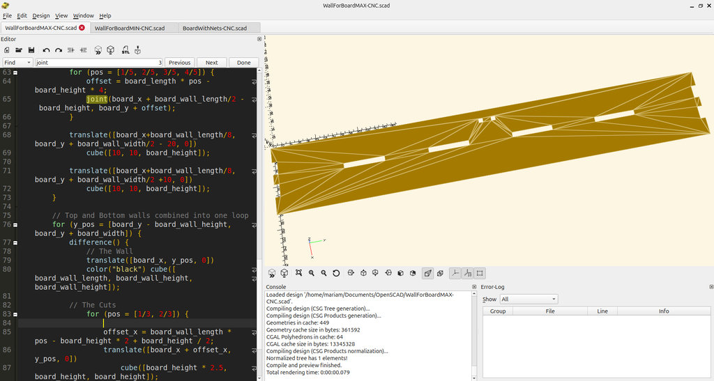
}2. Side Wall Sectionse
Next, I separated the side wall elements, which are attached to the base.
For these walls, I added joints, and the number of joints is defined parametrically. Using the loop: for (pos = [1/3, 2/3])
I define how many joints should be placed. In this case, there are 2 joints.
If I wanted 4 joints, the loop could be modified as: for (pos = [1/5, 2/5, 3/5, 4/5])
These wall parts will also be cut from 12 mm thick material.
Below is the image and the code for this part.
And all code:
board_x = 5;
board_y = 5;
board_z = 0;
board_length = 1000;
board_width = 1000;
board_height = 12;
board_wall_length = 160;
board_wall_width = 1000;
board_wall_height = 12;
board_wall_j_width = 6;
board_wall_j_length = 6;
board_wall_j_height = 12;
kerf = 0.3;
wall_j_width = 6;
wall_j_length = 6;
wall_j_height = 12;
wall_height = 60;
cell_size = board_length/10;// it's equal to car width/length(will be fine if car be quadrat)
module board(x, y, z, length, width, height) {
translate([x, y, z])
color("orange")
cube([length , width, height]);
}
module set_board_nets(x, y, z, length, width, height) {
for(i = [board_x + cell_size : cell_size/2 : (board_length)]) {
for(j = [board_y + cell_size : cell_size/2 : board_width]){
translate([i, j, 0])
color("red")
cube([length, width, height]);
}
}
}
module BoardWithNets() {
difference() {
board(board_x, board_y, board_z, board_wall_length, board_width, board_height);
set_board_nets(board_x, board_y, board_z+2, wall_j_width, wall_j_length, wall_j_height);
}
}
module joint(tx, ty) {
translate([tx, ty, 0]) color("black") cube([board_height - kerf, board_height * 8, board_height]);
}
projection(cut = false) {
union(){
// joints inner wall
difference() {
board(board_x, board_y, board_z, board_wall_length, board_width, board_height);
for (pos = [1/5, 2/5, 3/5, 4/5]) {
offset = board_length * pos - board_height * 4;
joint(board_x + board_wall_length/2 - board_height, board_y + offset);
}
translate([board_x+board_wall_length/8, board_y + board_wall_width/2 - 20, 0])
cube([10, 10, board_height]);
translate([board_x+board_wall_length/8, board_y + board_wall_width/2 +10, 0])
cube([10, 10, board_height]);
}
// Top and Bottom walls combined into one loop
for (y_pos = [board_y - board_wall_height, board_y + board_width]) {
difference() {
// The Wall
translate([board_x, y_pos, 0])
color("black") cube([board_wall_length, board_wall_height, board_wall_height]);
// The Cuts
for (pos = [1/3, 2/3]) {
offset_x = board_wall_length * pos - board_height * 2 + board_height / 2;
translate([board_x + offset_x, y_pos, 0])
cube([board_height * 2.5, board_height, board_height]);
}
}
}
}
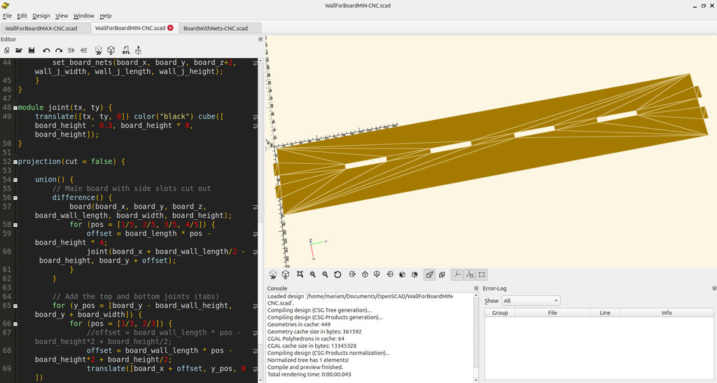
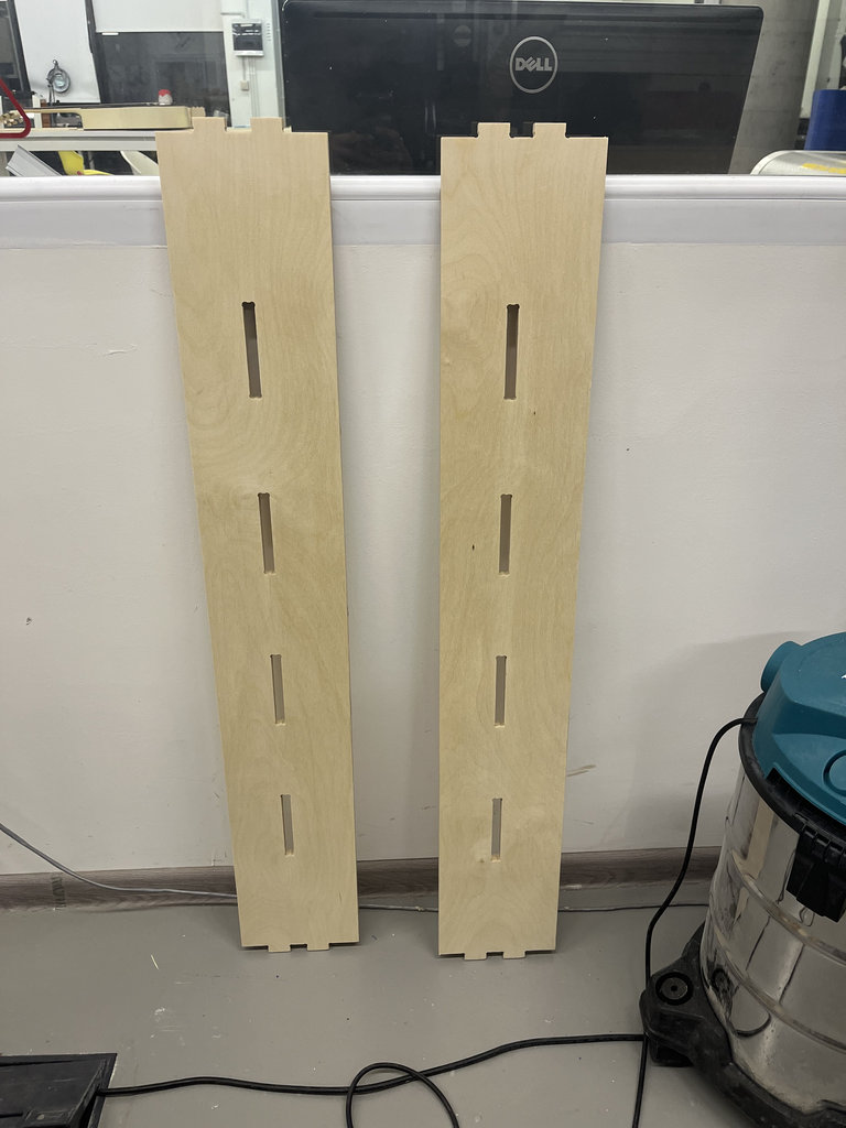
}3. Wall with Joint Receivers
This wall is the receiving part for the joints.
The number of joint slots is defined using the same parametric logic as before.
2 pieces should be cut from each of these walls.
Below is the image and the code.
board_x = 5;
board_y = 5;
board_z = 0;
board_length = 1000;
board_width = 1000;
board_height = 12;
board_wall_length = 160;
board_wall_width = 1000;
board_wall_height = 12;
board_wall_j_width = 6;
board_wall_j_length = 6;
board_wall_j_height = 12;
wall_j_width = 6;
wall_j_length = 6;
wall_j_height = 12;
wall_height = 60;
kerf = 0.3;
cell_size = board_length/10;// it's equal to car width/length(will be fine if car be quadrat)
module board(x, y, z, length, width, height) {
translate([x, y, z])
color("orange")
cube([length , width, height]);
}
module set_board_nets(x, y, z, length, width, height) {
for(i = [board_x + cell_size : cell_size/2 : (board_length)]) {
for(j = [board_y + cell_size : cell_size/2 : board_width]){
translate([i, j, 0])
color("red")
cube([length, width, height]);
}
}
}
module BoardWithNets() {
difference() {
board(board_x, board_y, board_z, board_wall_length, board_width, board_height);
set_board_nets(board_x, board_y, board_z+2, wall_j_width, wall_j_length, wall_j_height);
}
}
module joint(tx, ty) {
translate([tx, ty, 0]) color("black") cube([board_height - kerf, board_height * 8, board_height]);
}
projection(cut = false) {
union() {
// Main board with side slots cut out
difference() {
board(board_x, board_y, board_z, board_wall_length, board_width, board_height);
for (pos = [1/5, 2/5, 3/5, 4/5]) {
offset = board_length * pos - board_height * 4;
joint(board_x + board_wall_length/2 - board_height, board_y + offset);
}
}
// Add the top and bottom joints (tabs)
for (y_pos = [board_y - board_wall_height, board_y + board_width]) {
for (pos = [1/3, 2/3]) {
//offset = board_wall_length * pos - board_height*2 + board_height/2;
offset = board_wall_length * pos - board_height*2 + board_height/2;
translate([board_x + offset, y_pos, 0])
color("black")
cube([board_height * 2.5, board_height, board_height]);
}
}
}
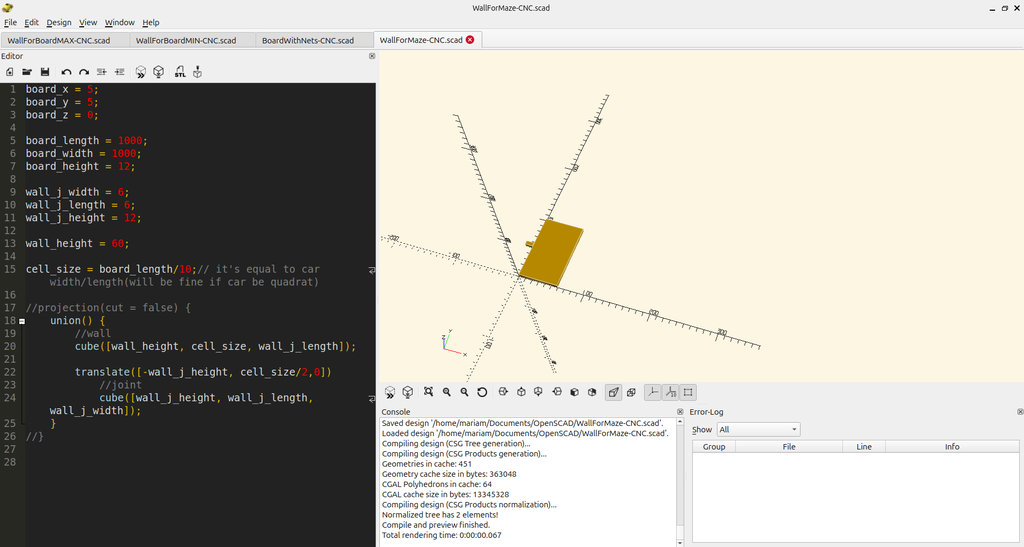
}4. Labyrinth Walls
Finally, these are the labyrinth wall pieces.
In total, 64 wall elements must be cut.
My design logic is the following:
- The entire board is divided into 4 quarters.
- In each quarter, 16 walls are placed randomly.
- Therefore, for four quarters we need:
4 × 16 wall pieces = 64 walls
These walls will be cut from 6 mm thick material.
Below is the image and the corresponding code.
board_x = 5;
board_y = 5;
board_z = 0;
board_length = 1000;
board_width = 1000;
board_height = 12;
wall_j_width = 6;
wall_j_length = 6;
wall_j_height = 12;
wall_height = 60;
cell_size = board_length/10;// it's equal to car width/length(will be fine if car be quadrat)
projection(cut = false) {
union() {
//wall
cube([wall_height, cell_size, wall_j_length]);
translate([-wall_j_height, cell_size/2,0])
//joint
cube([wall_j_height, wall_j_length, wall_j_width]);
}
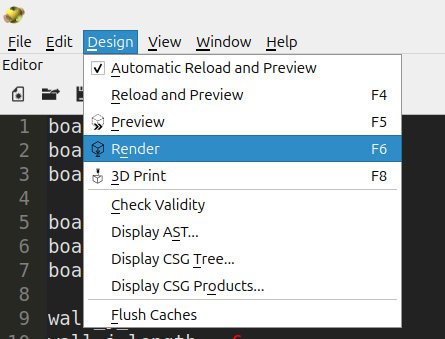
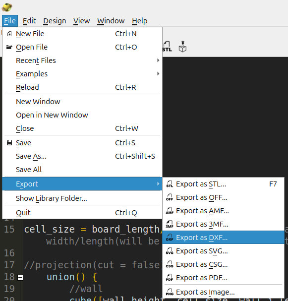
}All the files created in OpenSCAD must be rendered and then exported in DXF format.
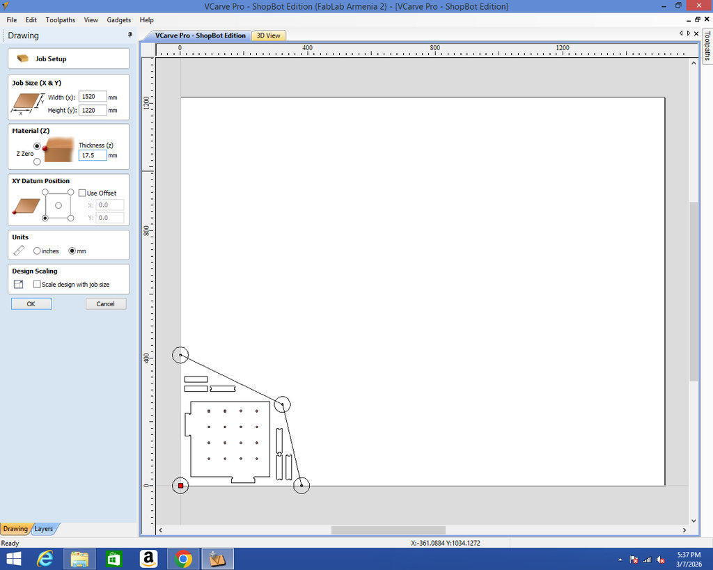
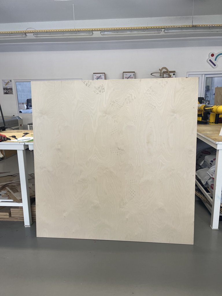
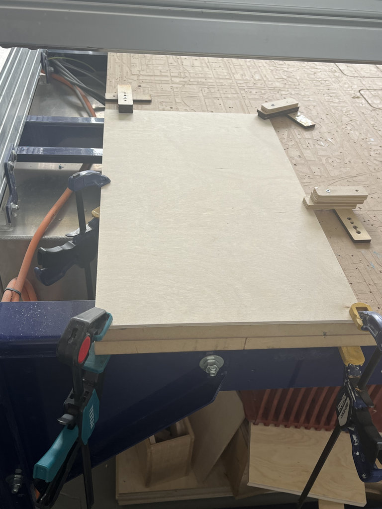
From our FabLab, I took a 1500 mm × 1500 mm wood sheet. I divided it into two sections: 1100 mm × 1500 mm and 400 mm × 1500 mm.
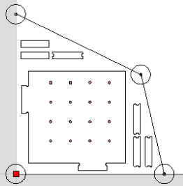
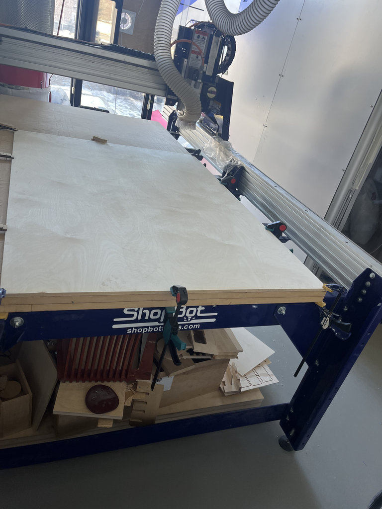
I placed the larger piece on the CNC machine, fixed it securely, and then moved to the VCarve software to arrange the parts. During this process, I also considered the fixing areas by placing 60 mm diameter circular safety zones to protect the CNC machine.
While arranging the parts in VCarve, I maintained approximately 10 mm spacing between neighboring parts — slightly larger than the 6 mm end mill diameter, to ensure enough clearance for machining while also maximizing material usage.
Except for the holes, all other parts are cut using a 6 mm milling bit. For this reason, I saved my design in two separate files, so that after changing the milling bit I can load the second file and continue the process.
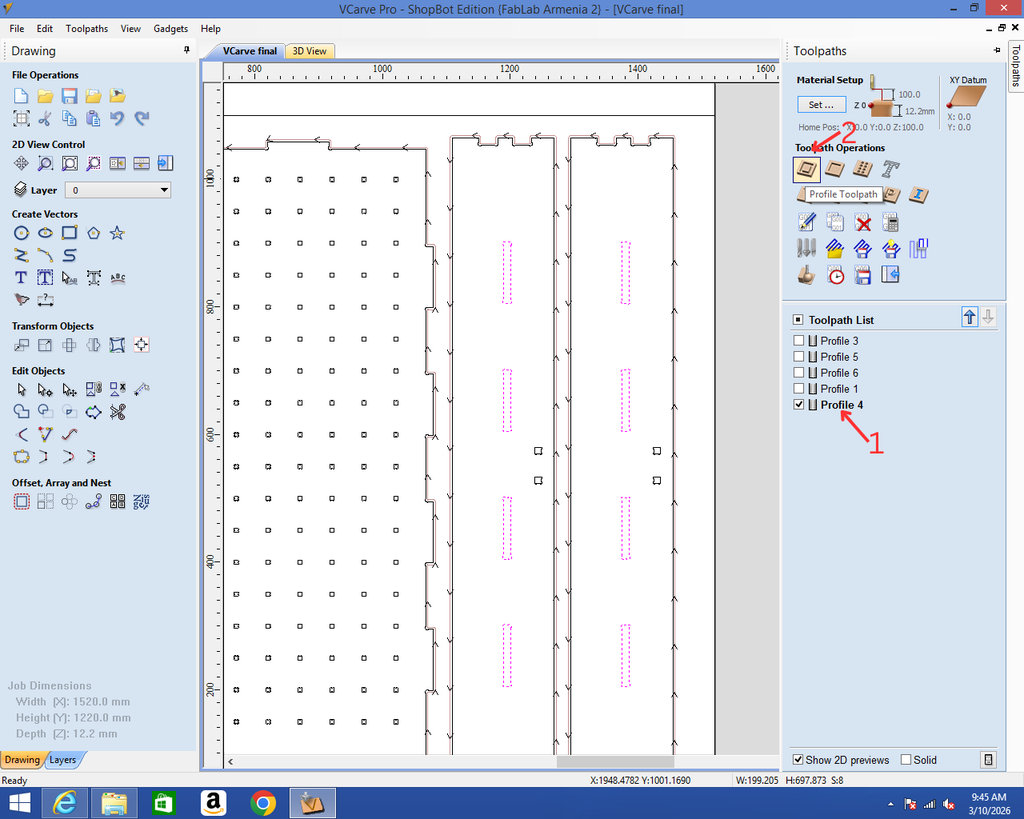
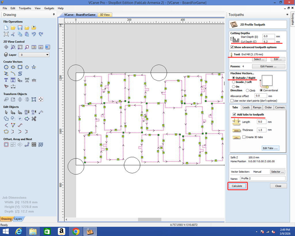
I selected the outer vectors and the joint sections and applied the Profile Toolpath command to cut them.
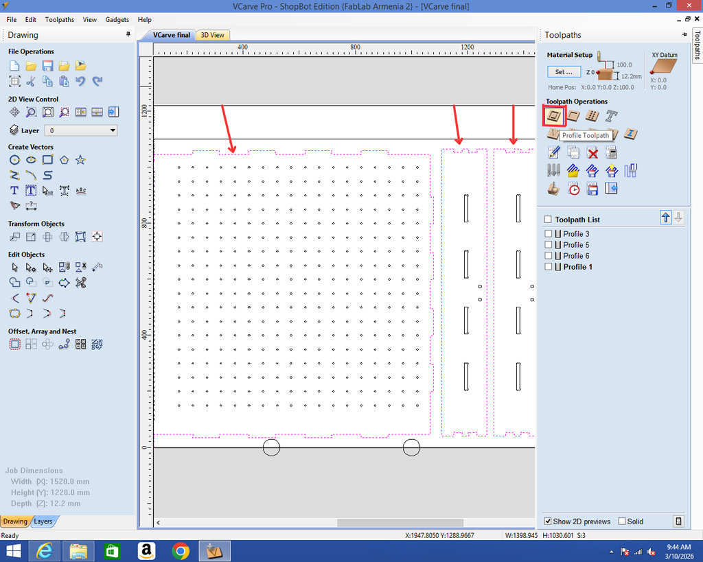
Then, by clicking on the created Profile, I opened the settings panel. Here it is necessary to select the correct milling bit size (6 mm) from the Tool → Select option.
I set Machine Vectors to Outside so that the corner edges are cut correctly and the dimensions of the design remain accurate.
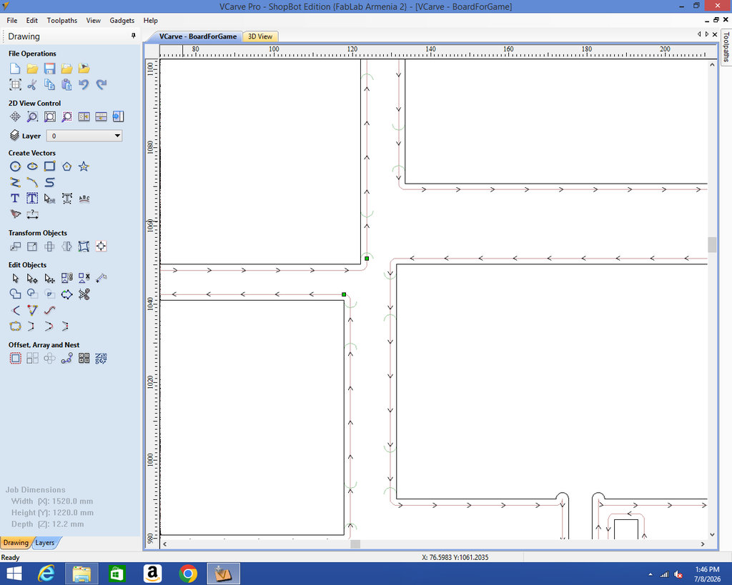
Using the Add Tabs to Toolpath option, I added tabs to keep the pieces attached to the main board so that they do not detach during the cutting process.
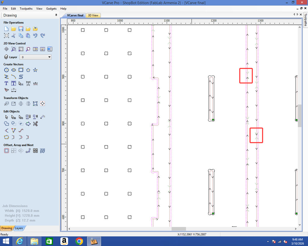
After pressing Calculate, the green arcs indicate the positions of the added tabs.
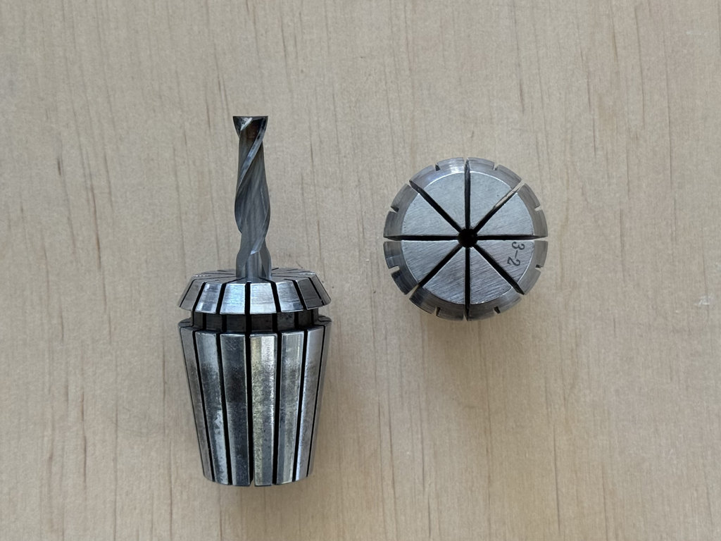
And here is the process of selecting the milling bit (mill).
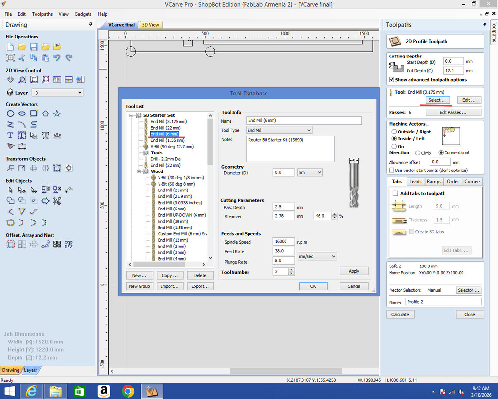
And here is the 6 mm milling bit with its holder, as well as the holder for the 3 mm milling bit.
We selected an UpCut type mill, because this type of bit is commonly used for producing mortises, deep grooves, and blind holes.
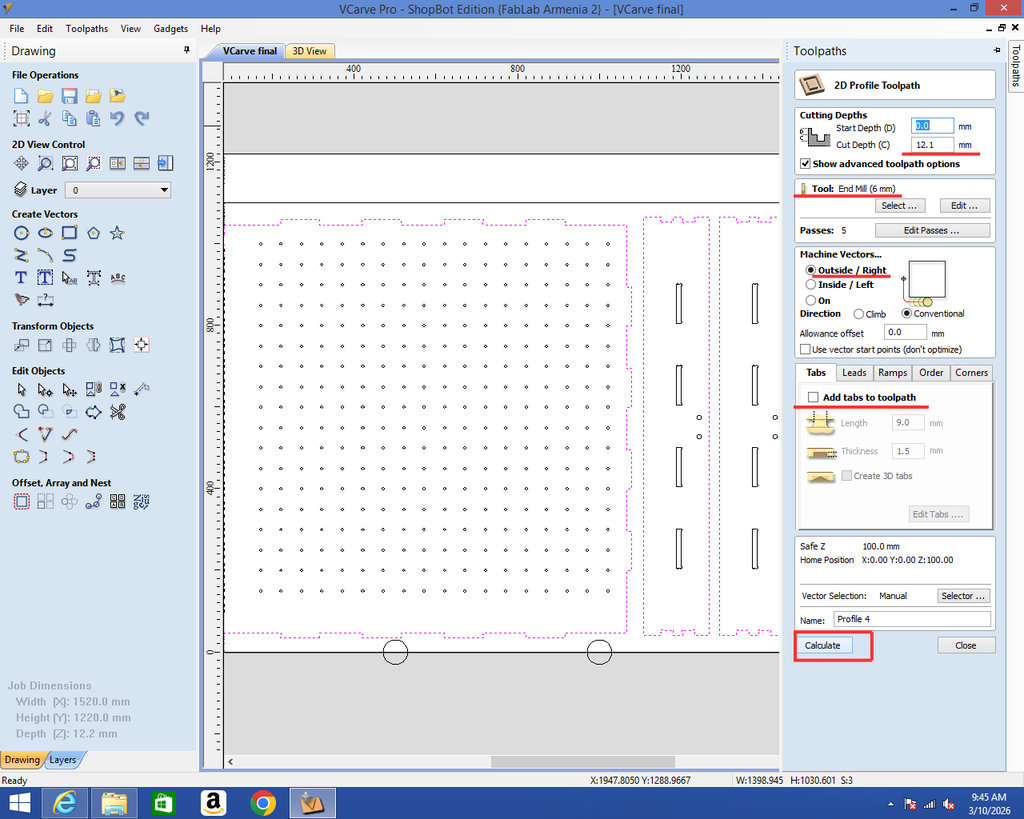
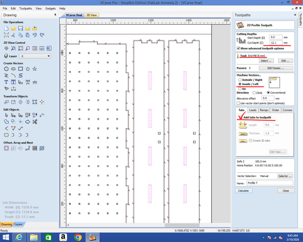
For the joints, I again create a Profile Toolpath. By clicking on the created profile, I configure the settings as shown in the image below.
Since my plywood thickness is 12 mm, I set the cut depth to 12.1 mm. This is because the CNC surface is not perfectly leveled, so adding an extra 0.1 mm ensures a complete cut.
From the Tool section, I select the correct mill.
For Machine Vectors, I choose Inside, so the outer dimensions remain accurate.
I enable “Add tabs to toolpath” and place tabs in selected areas. It is better to place them near edges or corners (but not exactly on the corners), so that after cutting, the piece stays attached to the plywood. Later, I will cut and sand those tabs.
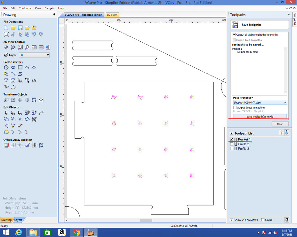
After clicking Calculate, I save all the settings.
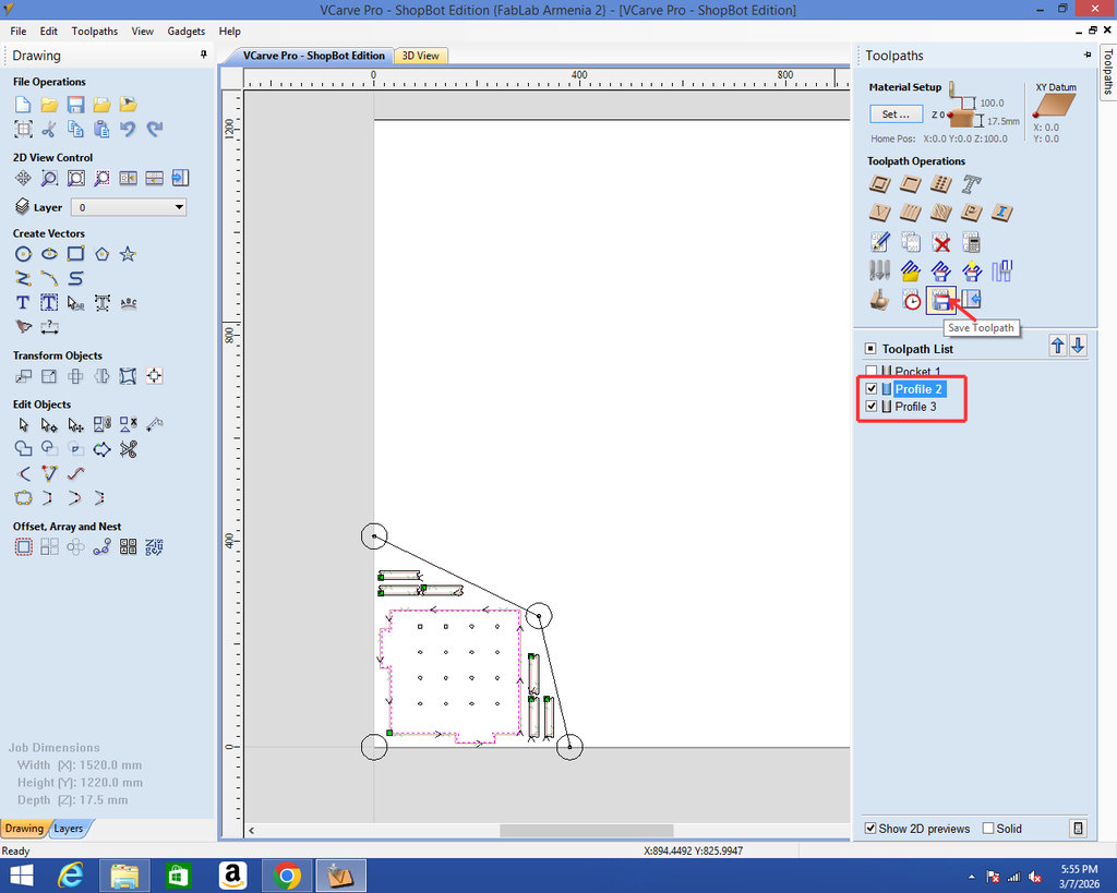
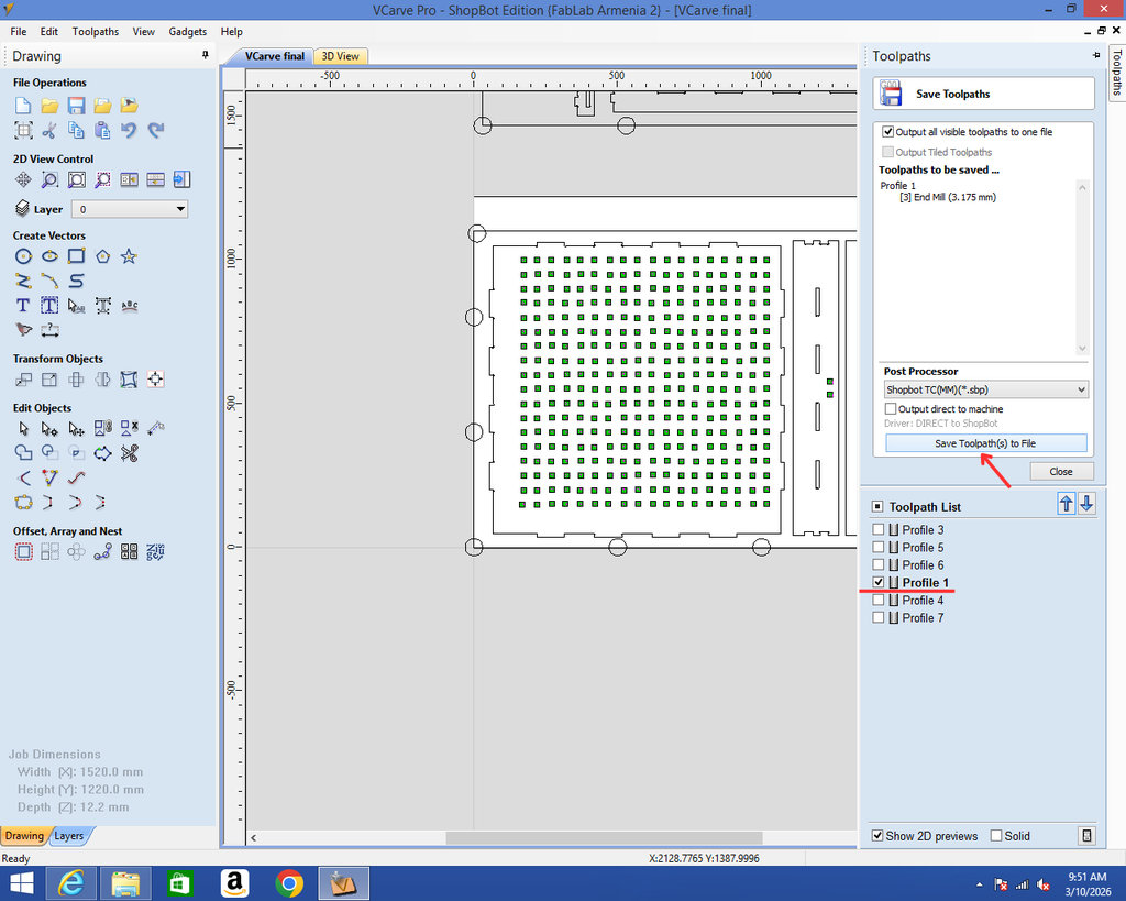
Then I save the profiles created for the joints and the side parts together in one place.
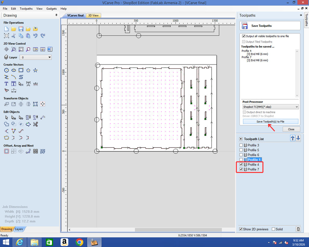
Now I apply the same settings for the slots, only changing the mill size to 3.175 mm, and then I save the file. I chose a 3.175 mm end mill because the holes on the board are 6 mm squares, and to achieve cleaner and more precise results, I used a smaller mill.
Then again choose Profile and Save Toolpath.
While arranging the parts in VCarve, I maintained approximately 10 mm spacing between neighboring parts. This spacing is slightly larger than the 6 mm end mill diameter, ensuring enough clearance for machining while also maximizing material usage.
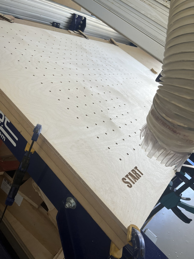
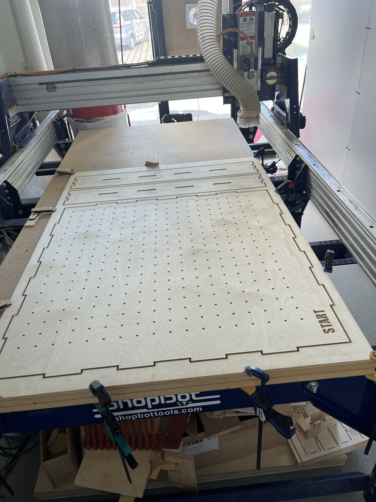
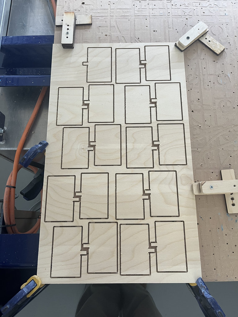
Here are photos from the cutting process.
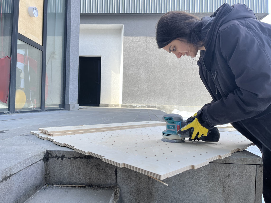
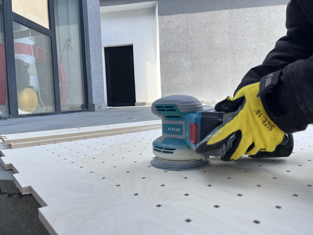
And here are photos from the sanding process.
Then I placed the smaller wood(400mmx1500mm) piece on the CNC machine and started the cutting process.
The process in VCarve of arranging the labyrinth walls, adding tabs, selecting the milling bit, and setting the cutting direction.
Then, I placed the corresponding plywood on the CNC machine.
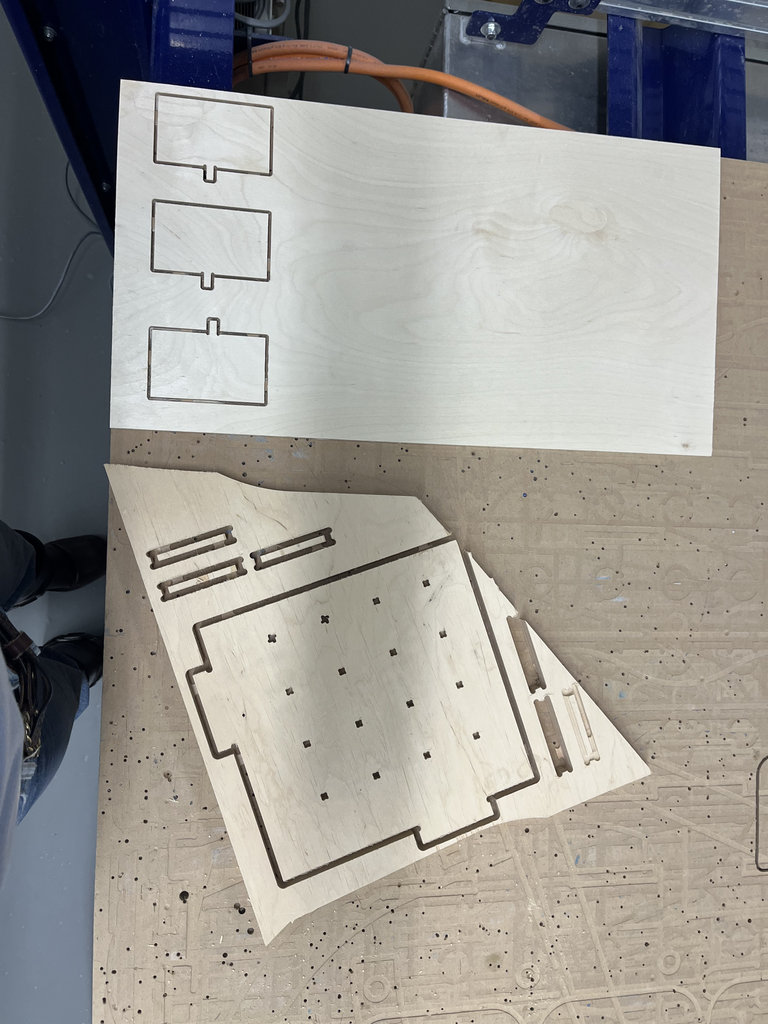
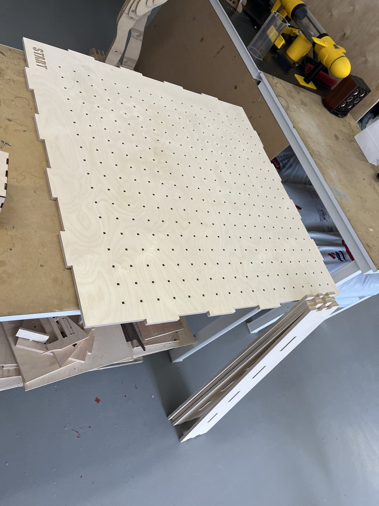
After that, the parts were ready in their cut form.
I repeated this process 5 more times, because the minimum number of pieces I needed was 64.
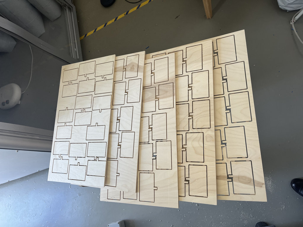
After that, I processed 90 wall pieces, which was definitely a long process.
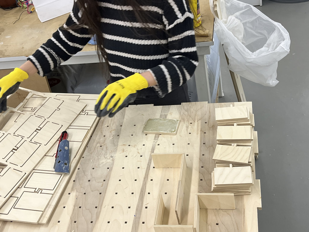
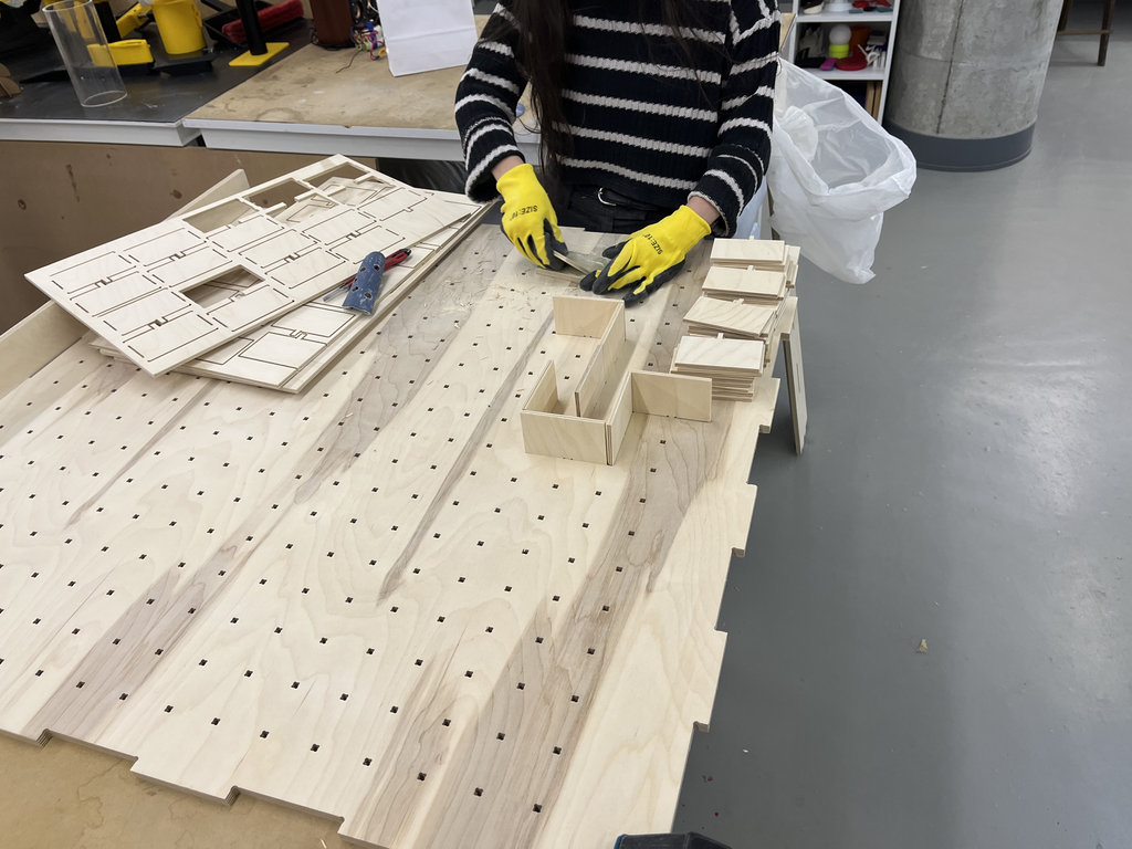
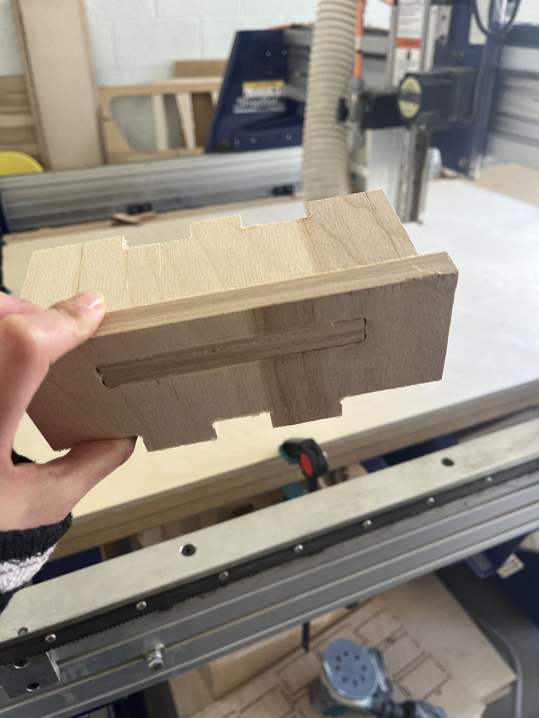
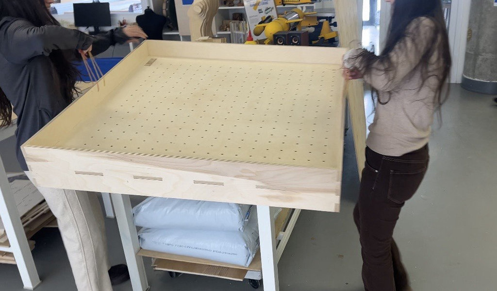
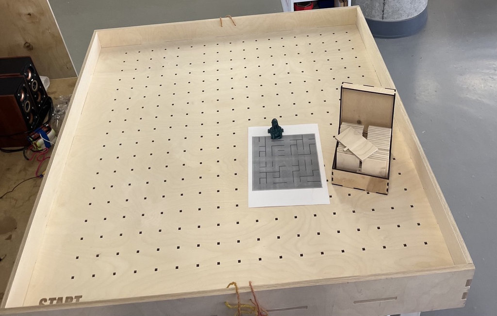
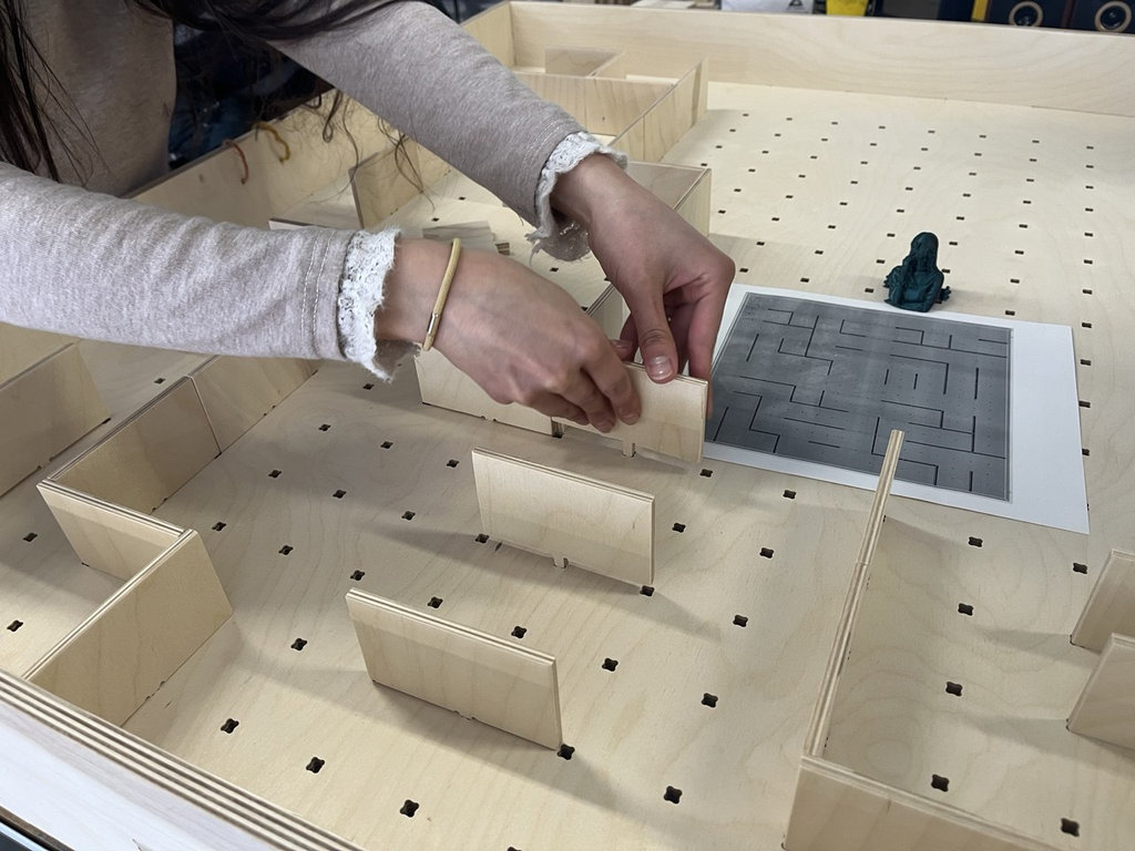
Then, we took one of the cards generated and printed in Week 3 using the randomizer, and as a team we started the assembly process. It was a very interesting and enjoyable experience.
During Week 7 – Computer-Controlled Machining, I learned how to design and manufacture large physical objects using a CNC machine. The main goal was to understand the complete workflow, starting from parametric design to toolpath generation and physical fabrication.
First, I designed the parts of my Final Project game board using OpenSCAD, creating a parametric labyrinth structure. I separated the design into several components such as the base plate, side walls with joints, joint receivers, and multiple internal labyrinth walls. This parametric approach allowed me to easily control dimensions, joint positions, and the number of elements.
Next, I exported the models to DXF format and prepared them in VCarve for machining. I arranged the parts on the wood sheet, defined safe fixing zones, and created Profile Toolpaths. I also learned how to correctly configure cutting parameters such as tool diameter, outside vector cutting, and tabs to keep the parts attached during machining.
During the machining process, I used two different milling bits: a 6 mm mill for larger cuts and a 3.175 mm mill for smaller slots and precise areas. After setting up the CNC machine and fixing the material, I successfully performed the cutting process.
As a result, I produced all the wooden components required for assembling the labyrinth board of my final project. This week helped me better understand the relationship between digital design, machining parameters, and real-world fabrication constraints.
Individual assignment

AI prompt:
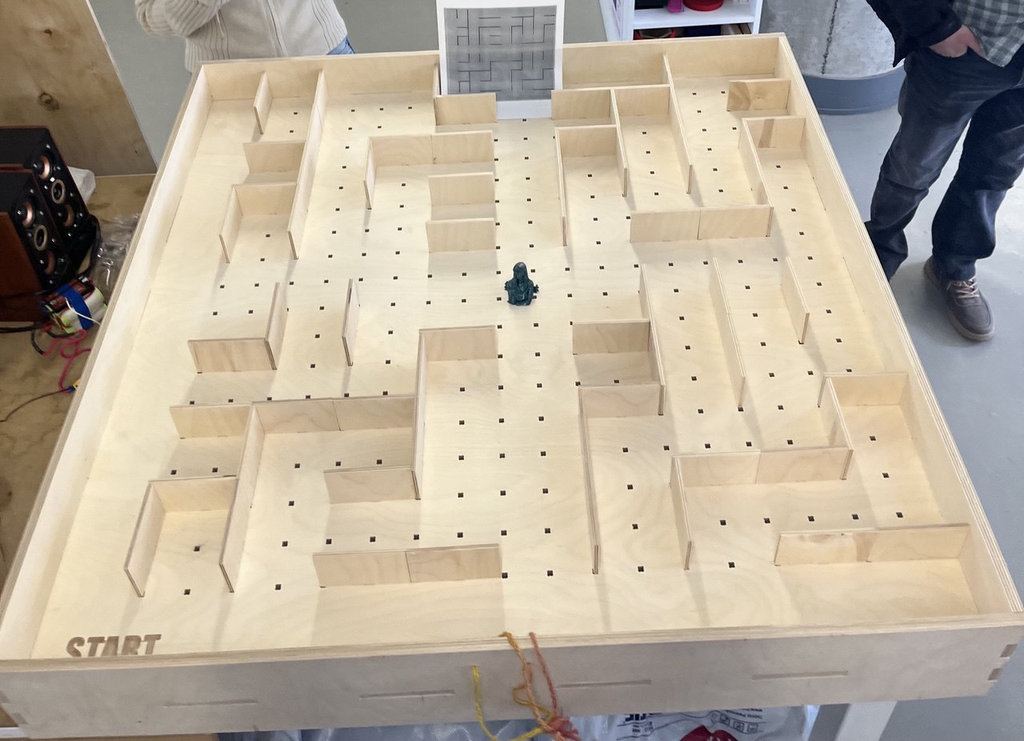
“and generate a new image when finished, week 7 " computer-controlled machining" The board is ready for the game.”