
Week 4

AI prompt:
“This week 4 need to learn embedded programming. We explore what is microcontrollers, Arduino and Stm32, c, c++ and Arduino ide. Uart pio. Can you generate image when grandmothers of this image started this week?”
Embedded Programming
This week, we thoroughly studied how microcontrollers work, became familiar with the tools required to program them, and learned the theoretical differences between them. I can confidently say that programming microcontrollers is one of the most interesting directions in programming because it combines both coding and creativity.
Group assignment
During the group assignment, I learned that the goal was not only to program a microcontroller but also to understand the complete development workflow, often referred to as the toolchain. A toolchain includes everything required to develop embedded software, such as installing the programming environment, selecting the correct board and communication port, compiling the code, uploading the firmware, and testing the result.
By comparing different development environments, I better understood that each platform has its own workflow, advantages, and target applications. Although they all allow programming microcontrollers, the development experience is different depending on the board and software being used.
📊 Comparison of Development Platforms
| Development Board | Programming Language | Development Environment | Advantages |
|---|---|---|---|
| Arduino Uno | C/C++ | Arduino IDE | Beginner-friendly, many examples, large community. |
| Seeed Studio XIAO RP2040 | MicroPython | Thonny IDE | Easy to prototype, interactive programming, and simple debugging. |
💭 Personal Reflection
The group assignment helped me understand that programming embedded systems is more than simply writing code. Each platform follows a different development workflow, from configuring the programming environment to uploading and debugging the firmware. Exploring both Arduino IDE and MicroPython allowed me to compare different approaches and gave me a better understanding of which tools are most suitable for different types of embedded projects.
Individual assignment
Arduino Uno, C++
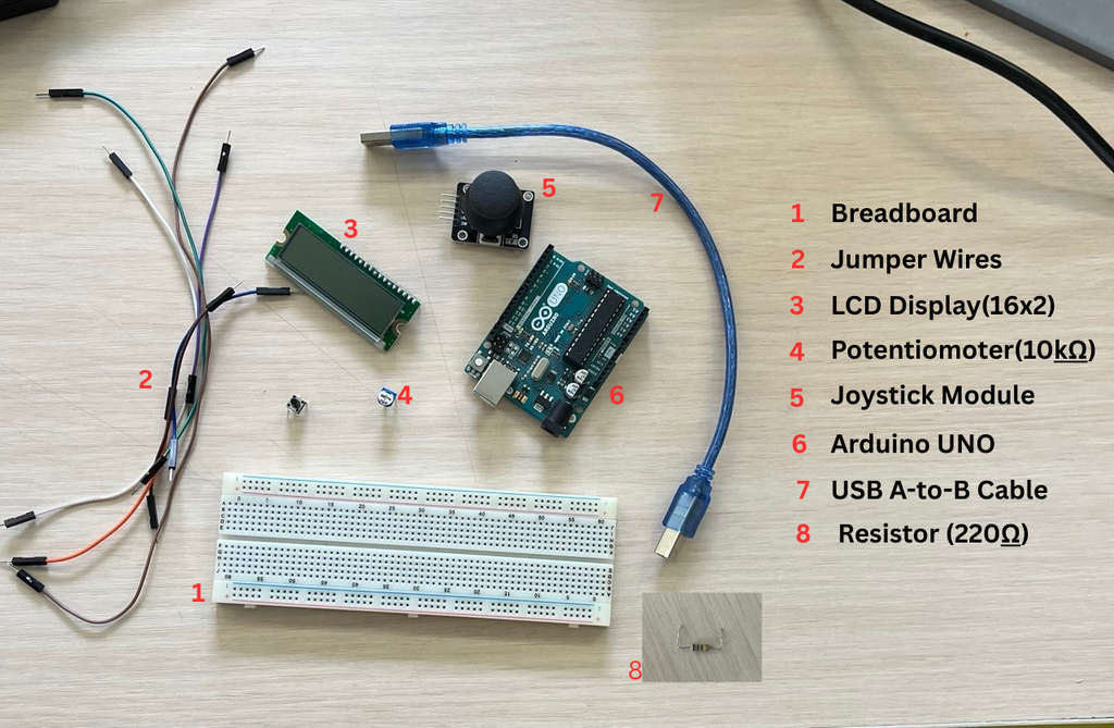
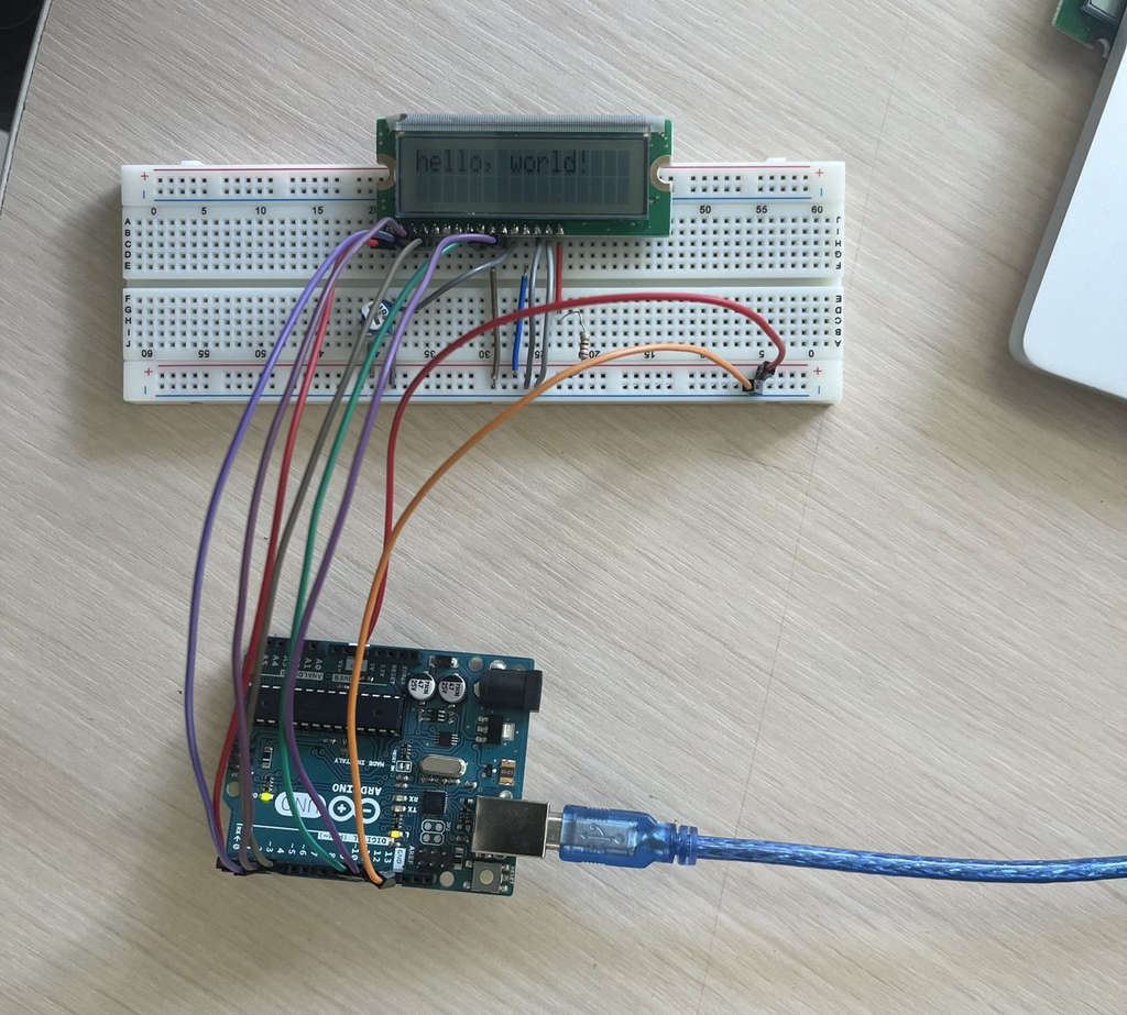
At first, I began my experiments with a simpler setup, meaning I started programming on the Arduino Uno. To make the assignment slightly more challenging, I decided to display the classic “Hello World” message along with a timer. However, this time I used an LCD screen that did not include a built-in potentiometer, which meant I had to assemble the full circuit on a breadboard. The required components are shown in the image.
💡 My First Blink Program
Before starting my experiments, I explored the Arduino Uno documentation and its pinout diagram to better understand the development board. The Arduino Uno is based on the ATmega328P microcontroller and provides 14 digital I/O pins, 6 analog input pins, and operates at 5V with a 16 MHz clock frequency. While reading the datasheet, I learned how the power pins, communication interfaces, and GPIO pins are organized, making it much easier to connect external components correctly.
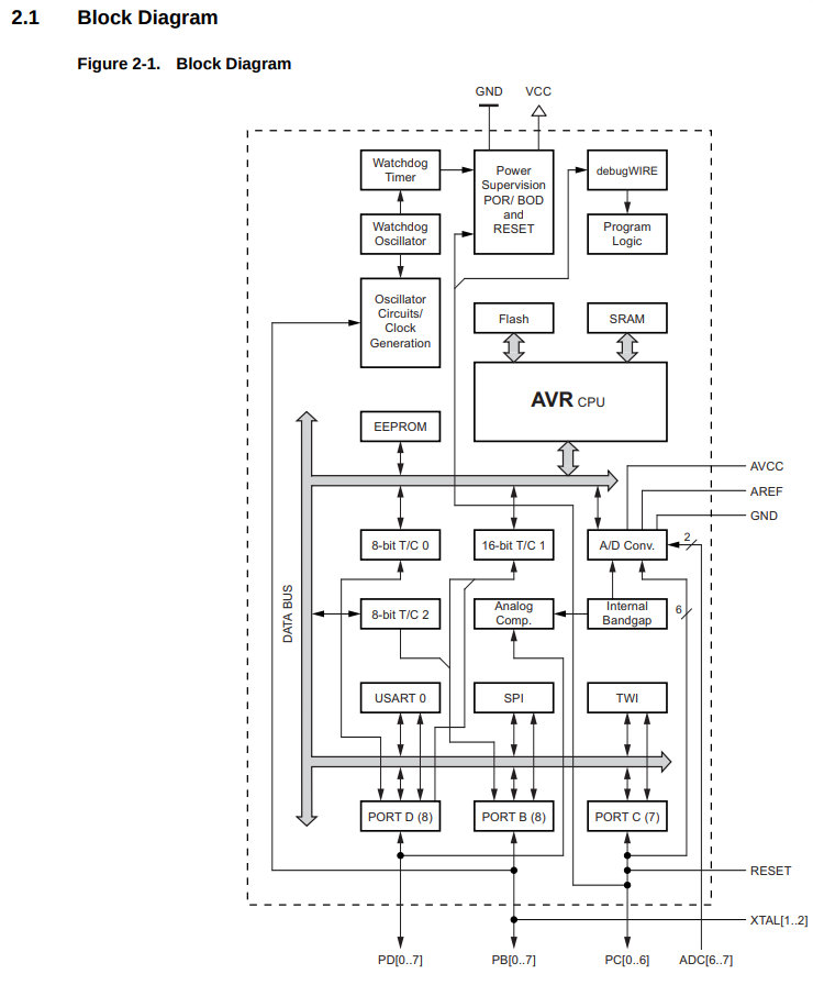
Before programming the Arduino Uno, I explored the ATmega328P datasheet to better understand the microcontroller. The pin diagram helped me identify the GPIO, power, UART, SPI and I2C pins. I also learned that the ATmega328P contains 32 KB Flash memory, 2 KB SRAM and 1 KB EEPROM, operates up to 20 MHz, and includes hardware timers, ADC channels and PWM outputs. Understanding these features helped me know which peripherals are available before writing any code.
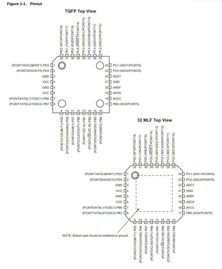
Before connecting any external components, I uploaded the classic Blink example to the Arduino Uno. This simple program helped me verify that the Arduino IDE was correctly installed, the board was properly connected, and the upload process was working successfully. Once I saw the onboard LED blinking, I continued with the LCD experiments.
#include <LiquidCrystal.h>

// initialize the library by associating any needed LCD interface pin
// with the arduino pin number it is connected to
const int rs = 12, en = 11, d4 = 5, d5 = 4, d6 = 3, d7 = 2;
LiquidCrystal lcd(rs, en, d4, d5, d6, d7);

void setup() {
	// set up the LCD's number of columns and rows:
	lcd.begin(16, 2);
	// Print a message to the LCD.
	lcd.print("hello, world!");
}

void loop() {
	// Turn off the blinking cursor:
	lcd.noBlink();
	delay(3000);
	// Turn on the blinking cursor:
	lcd.blink();
	delay(3000);
}
🎮 Joystick Connection
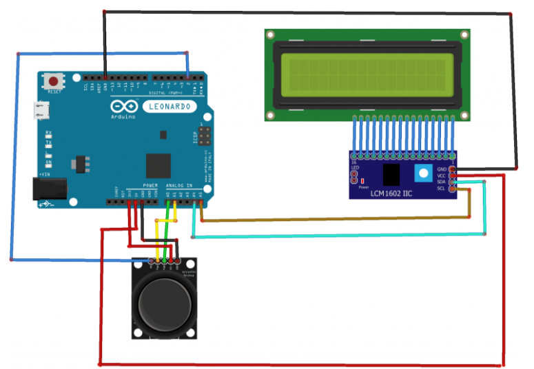
To reset the timer, I connected a joystick module instead of a regular push button because I plan to use a joystick in my final project. The joystick button (SW) was connected to digital pin D8, while VCC and GND were connected to the corresponding power pins on the Arduino Uno. The button was configured using the internal pull-up resistor, so it reads HIGH when released and LOW when pressed.
I started from the official Arduino LCD example to understand how the display works. After successfully displaying text, I gradually modified the example by adding a timer and a joystick button that resets the timer. I also used ChatGPT to better understand some Arduino functions and improve the structure of the program.
AI Prompt: "Help me create an Arduino LCD timer that resets when a joystick button is pressed."
#include <LiquidCrystal.h>          // Include the LCD library so I can control the display.

// Tell Arduino which pins are connected to the LCD.
LiquidCrystal lcd(12, 11, 5, 4, 3, 2);

// The joystick button (SW pin) is connected to digital pin 8.
const int JOYSTICK_BUTTON = 8;

// Variables used to keep track of the timer.
unsigned long startTime;
unsigned long elapsedTime;

// Variables that will store hours, minutes, and seconds.
byte seconds, minutes, hours;

void setup() {

  // Enable the internal pull-up resistor for the joystick button.
  pinMode(JOYSTICK_BUTTON, INPUT_PULLUP);

  // Initialize the 16x2 LCD display.
  lcd.begin(16, 2);

  // Print a title on the first row.
  lcd.print("Timer: ");

  // Save the current time as the starting point.
  startTime = millis();
}

void loop() {

  // If the joystick button is pressed...
  if (digitalRead(JOYSTICK_BUTTON) == LOW) {

    // ...restart the timer from zero.
    startTime = millis();
  }

  // Calculate how many seconds have passed.
  elapsedTime = (millis() - startTime) / 1000;

  // Get the seconds value.
  seconds = elapsedTime % 60;

  // Get the minutes value.
  minutes = (elapsedTime / 60) % 60;

  // Get the hours value.
  hours = (elapsedTime / 3600) % 100;

  // Move the cursor to the second row.
  lcd.setCursor(0, 1);

  // Print a leading zero if the hour has only one digit.
  if (hours < 10) lcd.print('0');
  lcd.print(hours);

  // Print the ":" separator.
  lcd.print(':');

  // Print a leading zero if needed.
  if (minutes < 10) lcd.print('0');
  lcd.print(minutes);

  // Print the next ":" separator.
  lcd.print(':');

  // Print a leading zero if needed.
  if (seconds < 10) lcd.print('0');
  lcd.print(seconds);

  // Clear any leftover characters from the previous value.
  lcd.print("   ");
}
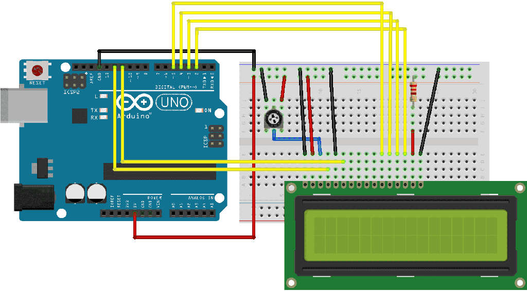
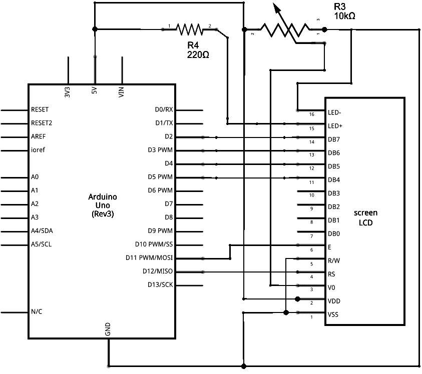
Connecting a joystick and an LCD to an Arduino Uno at the same time is not difficult. The wiring diagram can be found with a simple Google search. Here is the reference that I used: Using the joystick with Arduino.
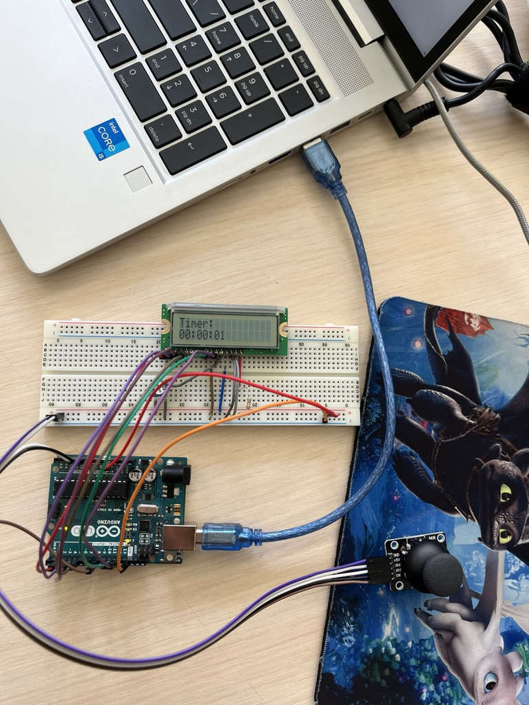
Here is the assembled circuit and a video demonstrating the result.
Thonny, Micropython
For the second experiment, I explored wired communication using the I2C protocol. I2C is a communication protocol that allows multiple devices to exchange data using only two signal lines: SDA (Serial Data) and SCL (Serial Clock). This greatly reduces the number of required wires compared to parallel communication, making the circuit cleaner and easier to assemble.
While browsing the datasheet, I learned several important things:
- The microcontroller includes 264 KB SRAM memory.
- It supports many communication protocols such as
UART,SPI, andI2C. - The chip has
GPIOpins that can be configured for different functions, such as digitalinput/output,PWM, andcommunication interfaces. - The
RP2040also supportsProgrammable IO (PIO), which allows creating custom hardware interfaces.
The required components were:
- Seeed Studio XIAO RP2040
- I2C LCD
- Wires
- Breadboard
- USB Cable
I learned that the RP2040 contains two Arm Cortex-M0+ cores running up to 133 MHz, 264 KB SRAM, programmable I/O (PIO), hardware timers and multiple communication peripherals including UART, SPI and I2C. The datasheet also explains how every GPIO pin can be configured for different peripheral functions, which helped me understand how the XIAO board maps its pins to the RP2040 microcontroller.
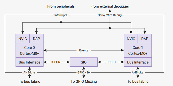
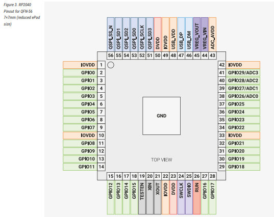
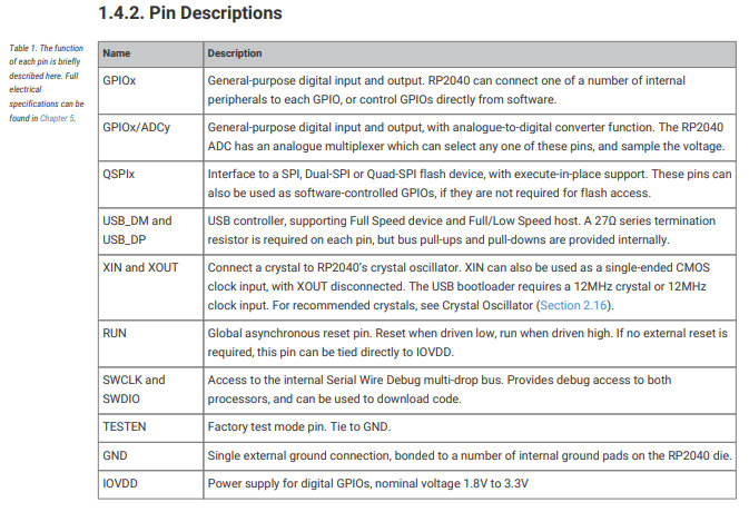
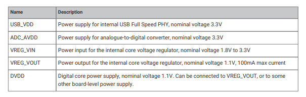
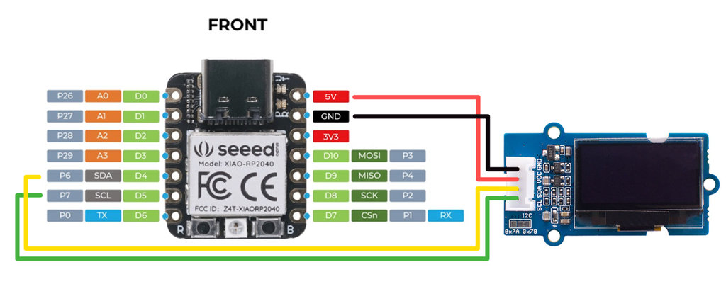
I assembled the circuit by reading the documentation from the Seeed Studio Wiki Platform and using the reference image shown below.
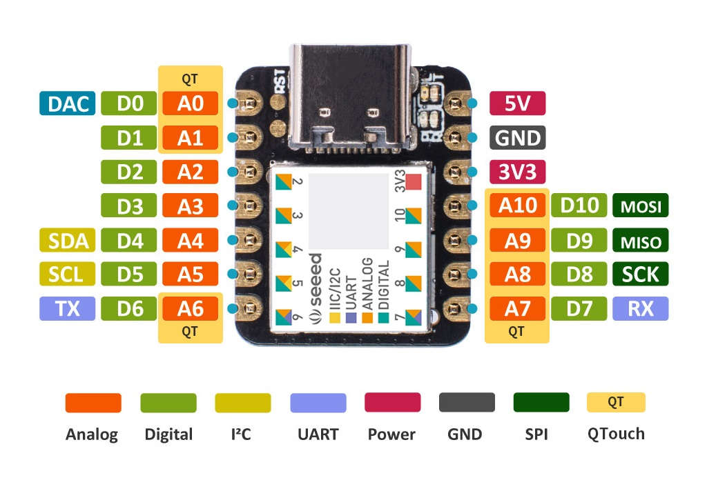
📺 MicroPython - Hello XIAO Result
To program using MicroPython, I installed Thonny. Since my computer and operating system had changed (not by my choice 😄), I installed it using the following method.
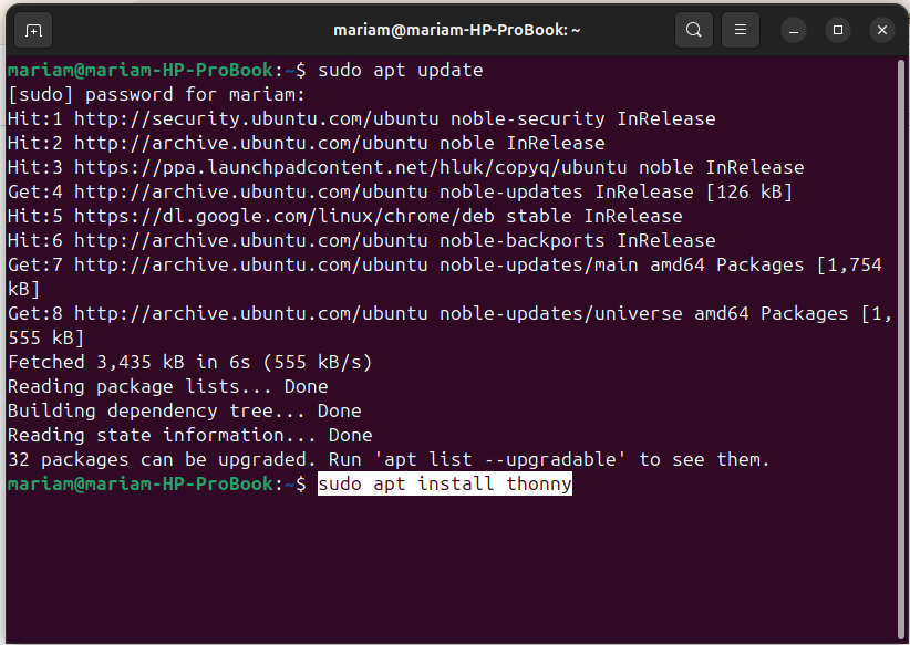
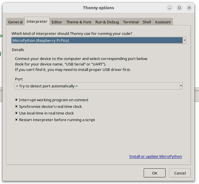
After completing the installation, I configured the settings by selecting Raspberry Pi Pico as the Interpreter and choosing the correct port. This step specifies the physical serial connection between the computer and the development board and selects the appropriate MicroPython port for the device.
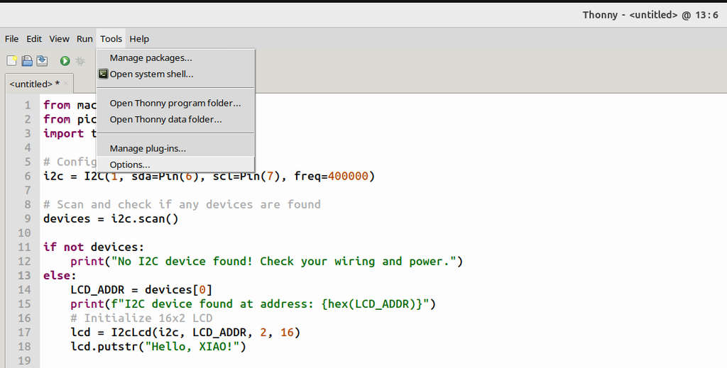
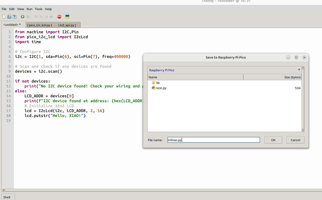
Next, I created a new file by navigating to File → New and wrote a simple program to print "Hello, XIAO!" on the LCD screen.
After pressing Save and Run, I encountered the following error.
from machine import I2C,Pin
	from pico_i2c_lcd import I2cLcd
	import time

	# Configure I2C
	i2c = I2C(1, sda=Pin(6), scl=Pin(7), freq=400000)

	# Scan and check if any devices are found
	devices = i2c.scan()

	if not devices:
	print("No I2C device found! Check your wiring and power.")
	else:
	LCD_ADDR = devices[0]
	print(f"I2C device found at address: {hex(LCD_ADDR)}")
	# Initialize 16x2 LCD
	lcd = I2cLcd(i2c, LCD_ADDR, 2, 16)
	lcd.putstr("Hello, XIAO!")
>>> %Run -c $EDITOR_CONTENT
	Traceback (most recent call last):
	File "<stdin>", line 2, in <module>
	ImportError: no module named 'pico_i2c_lcd'
	>>>
After researching and analyzing the issue, I realized that I needed to install two additional libraries. To interface an I2C LCD with MicroPython in Thonny, two library files are required:
- lcd_api.py – contains general LCD command functions
- pico_i2c_lcd.py – handles Pico-specific I2C communication
I created two new files and placed the corresponding code inside them (which I downloaded from the provided GitHub repository).
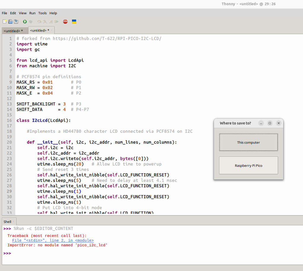
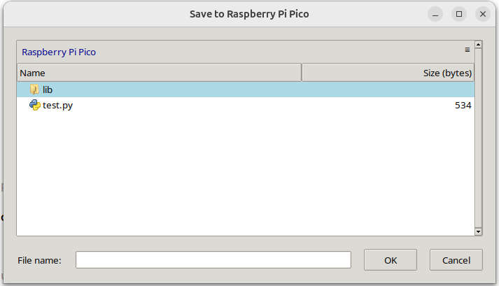
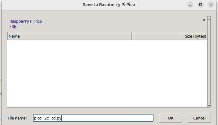
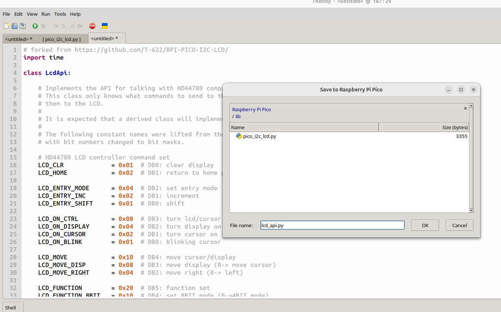
Here is the circuit diagram for the RP2040 and the I2C LCD from the Seeed Studio Wiki.
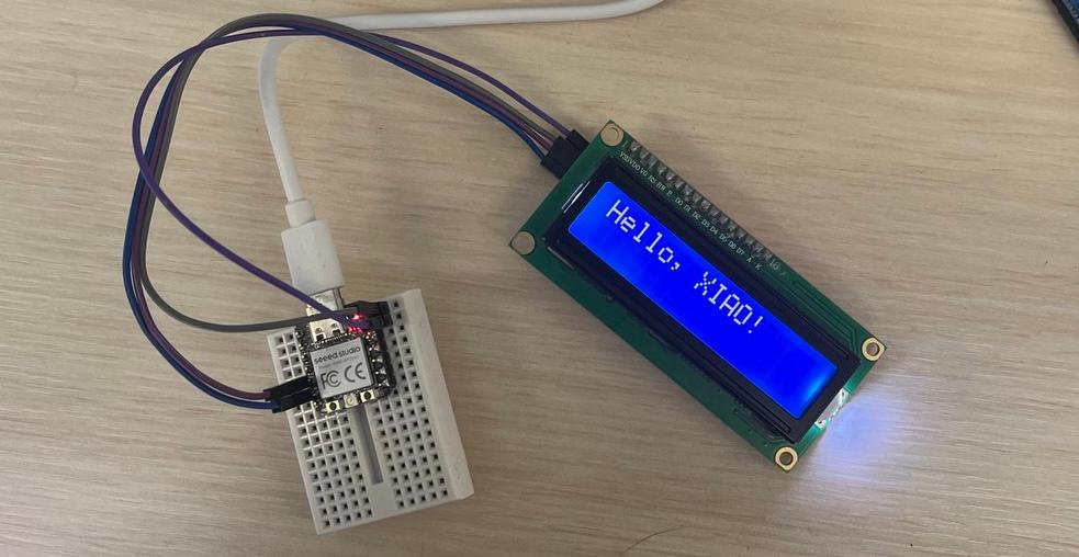
After installing the required libraries and configuring the I2C connection, I successfully displayed "Hello, XIAO!" on the LCD screen. This confirmed that the XIAO RP2040, the LCD, and the MicroPython environment were all communicating correctly before moving on to the timer project.
💻 MicroPython - How I Developed Timer
After confirming that the display worked correctly, I modified the program to implement a timer and added a push button to restart it. ChatGPT was also used to help understand several MicroPython functions and improve the code structure.
AI Prompt: "Help me write a MicroPython program for the XIAO RP2040 that displays a timer on an I2C LCD and resets when a button is pressed."
from machine import I2C, Pin
from pico_i2c_lcd import I2cLcd
import time

# Configure I2C
i2c = I2C(1, sda=Pin(6), scl=Pin(7), freq=400000)
button = Pin(26, Pin.IN, Pin.PULL_UP)

devices = i2c.scan()
if not devices:
	print("No I2C device found!")
else:
	lcd = I2cLcd(i2c, devices[0], 2, 16)

while True:
	lcd.clear()
	lcd.putstr("Timer Started!")
	start_time = time.ticks_ms()

while True:
	# 1. Calculate total elapsed seconds
	elapsed = time.ticks_diff(time.ticks_ms(), start_time) // 1000

	# 2. Break down into H:M:S
	hours = (elapsed // 3600)
	minutes = (elapsed % 3600) // 60
	seconds = elapsed % 60

	# 3. Display formatted time (00:00:00)
	lcd.move_to(0, 1)
	# :02d ensures 2 digits (e.g., 05 instead of 5)
	lcd.putstr(f"Time: {hours:02d}:{minutes:02d}:{seconds:02d}")

# Check for Reset Button
if button.value() == 0:
	time.sleep(0.2) # Simple debounce
	break

time.sleep(0.1)
In the RP2040 and I2C LCD circuit diagram shown above, I simply added one more component—a switch button. One pin of the switch button is connected to the RP2040's GND pin, while the other pin is connected to the D0 pin of the RP2040.
Video of timer working:
Since I was already familiar with both C++ and Python, programming a microcontroller was an interesting experience for me, even though I had a little previous experience with it. The RP2040 was new for me, and programming it with MicroPython was quite simple and enjoyable. The only challenge was manually downloading and adding the lcd_api.py and pico_i2c_lcd.py libraries for the LCD display. Overall, it was a useful experience that helped me better understand embedded programming.
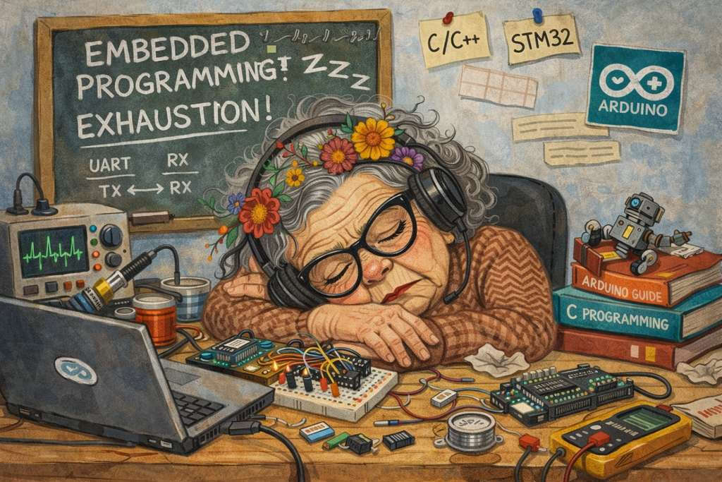
AI prompt:
“And generate an image when finished this week.”