
Week 5
AI prompt:
“Can you gnerate image when she started week 5? She learned 3d Scann and 3d printed proces, printed her coursemate 3d scanned model and designed with FreeCAD Eyes, and printed colourful Eyes.”
3D Scanning and Printing
During the Group Assignments, we evaluated the printing capabilities of the Elegoo Neptune 4 Max using several calibration models. The temperature tower helped determine the optimal printing temperature for both PLA and PETG. The Max Flowrate test showed the maximum extrusion speed that still produced reliable results, while the Mini All-in-One test evaluated overhangs, bridges, dimensional accuracy, clearances, thin walls, and stringing. These experiments helped me better understand the printer's limitations and allowed me to choose more appropriate settings for my individual assignment.
Based on the calibration tests performed during the group assignment, I summarized the most important design rules that I will follow when preparing future models for the Elegoo Neptune 4 Max.
| Design Rule | Result / Recommendation |
|---|---|
| PLA Nozzle Temperature | 220°C (manufacturer recommendation: 190–220°C) |
| PLA Heated Bed Temperature | 60°C (manufacturer recommendation: 45–60°C) |
| PETG Printing Temperature | Best results between 220°C and 250°C |
| Maximum PLA Flow Rate | Approximately 5–10 mm³/s |
| Maximum PETG Flow Rate | Approximately 5–12 mm³/s |
| Maximum Overhang | Up to about 60° without significant defects. |
| Bridging Performance | Short bridges printed successfully without supports. |
| Thin Walls | Very thin walls began to deform, so extremely thin features should be avoided. |
| Stringing | Only minimal stringing was observed after selecting the proper printing temperature. |
| Design Clearance | Moving parts should include sufficient clearance, and a calibration print is recommended before printing final functional models. |
These calibration tests helped me better understand the capabilities and limitations of the printer. As a result, I now have a set of practical design rules that I can apply when preparing future 3D models for printing.
This week was full of information for me. At the same time, it was very interesting, and now my main task is to properly document everything I have learned and tested. I hope everything will go smoothly 😊
3D printing
Designing Process - Free Cad
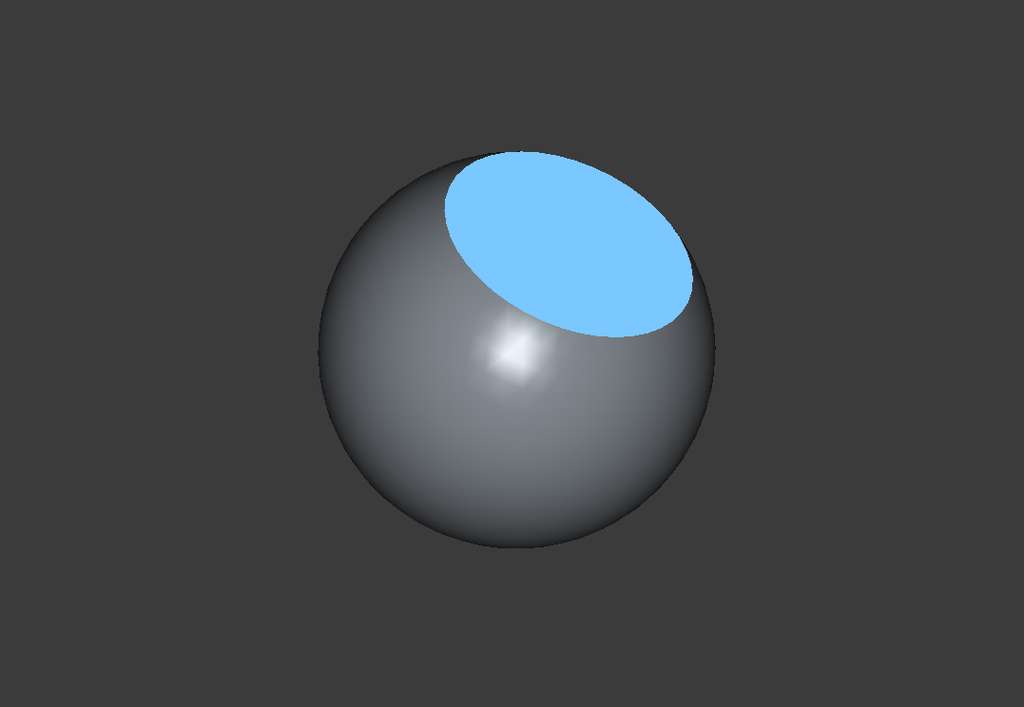
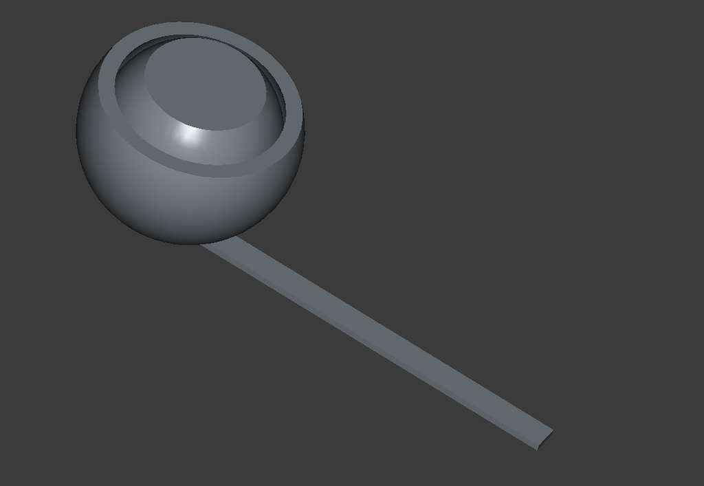
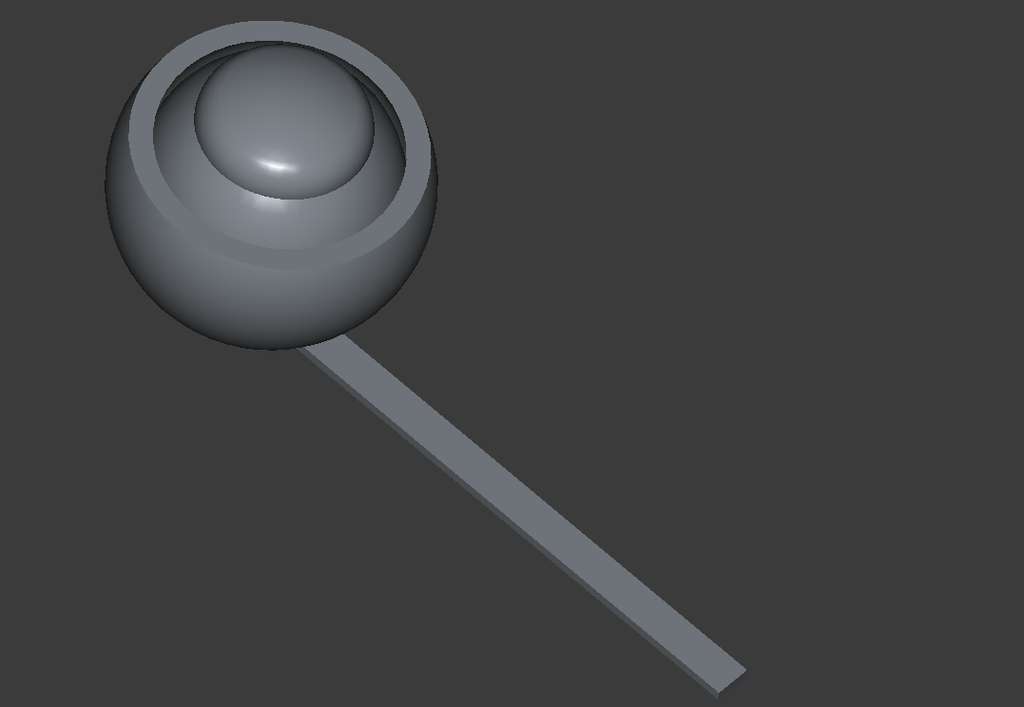
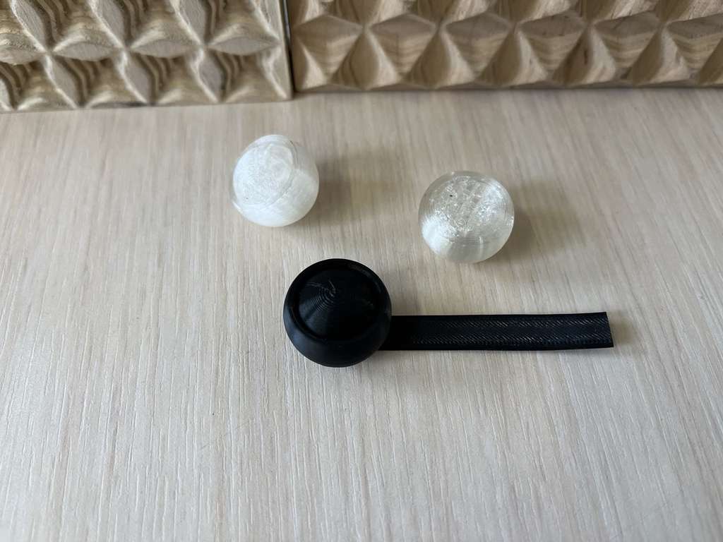
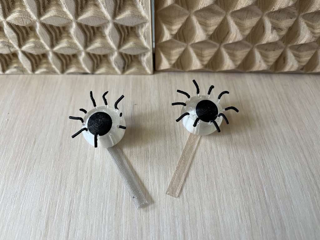
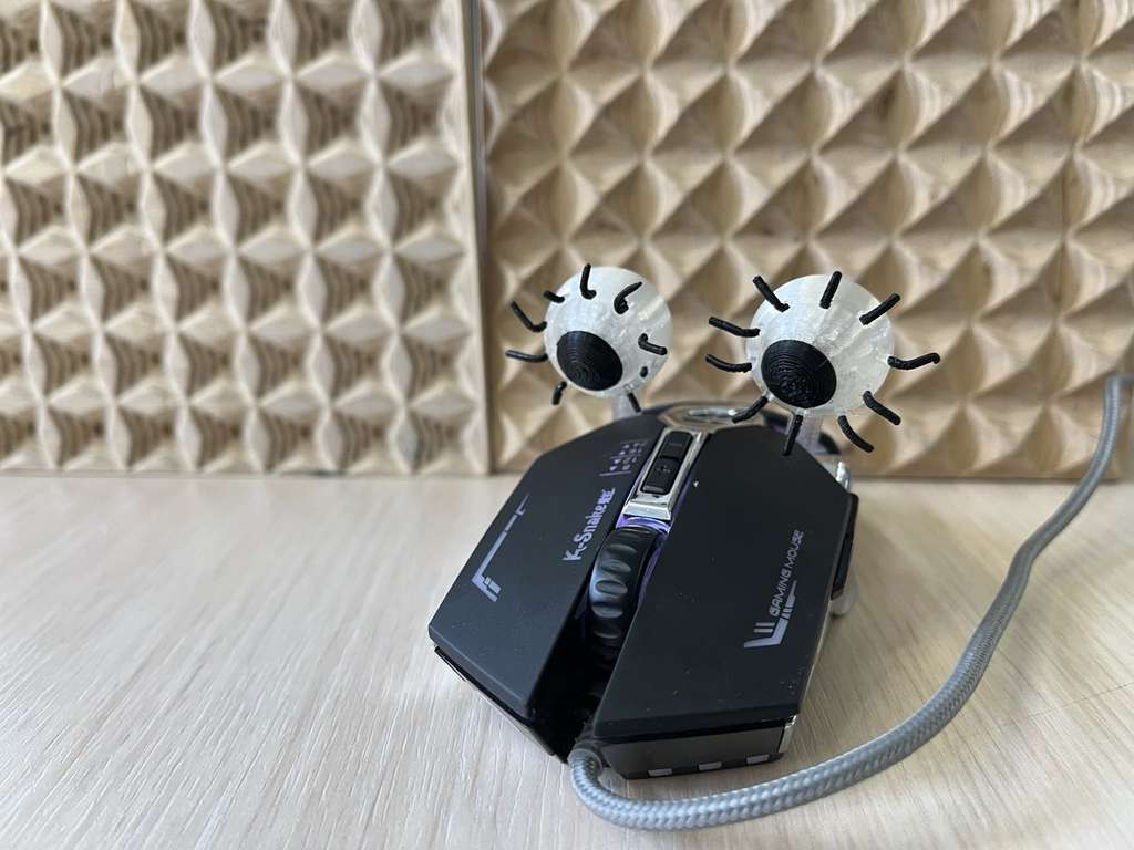
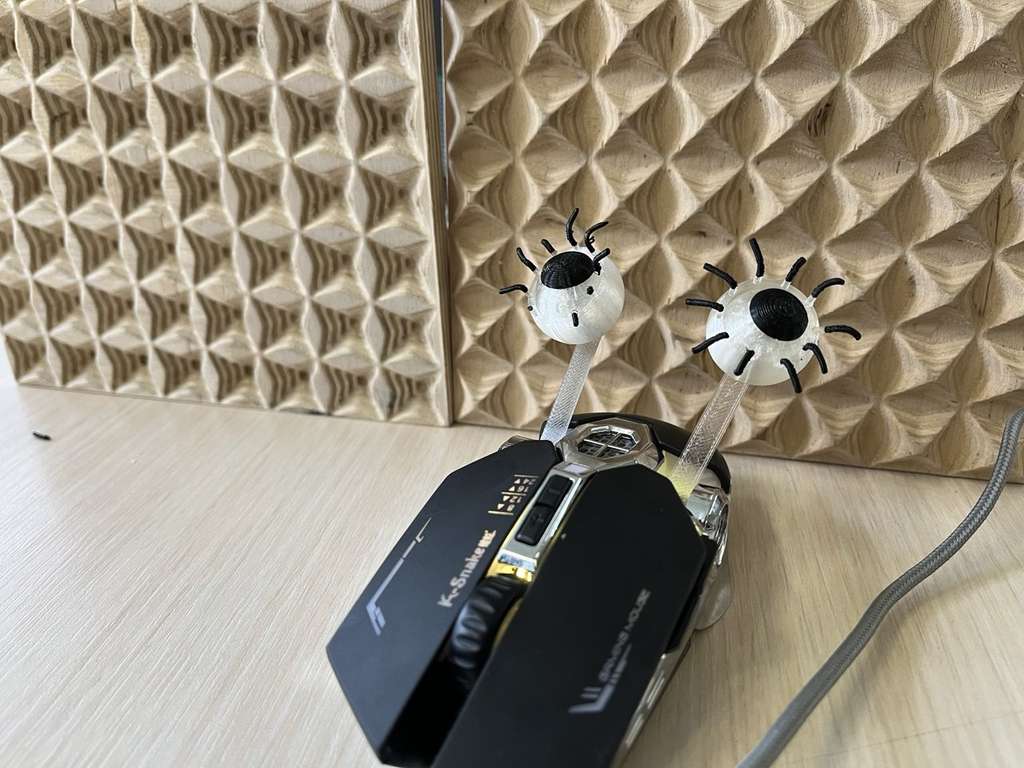
In addition, I decided to print the eyes for my final project car-robot. The goal was to design eyes that would move when attached to the vehicle and set in motion. In other words, I created a model where a small inner sphere can move freely inside a larger, partially enclosed sphere.
Why this model cannot be produced using subtractive manufacturing
The 3D printed eyes contain curved surfaces and undercuts that would be difficult to reach using subtractive manufacturing tools such as CNC milling. Since CNC tools remove material from the outside, they cannot easily create internal shapes or recessed features. Additive manufacturing allows the object to be built layer by layer, making these geometries possible.
The model was designed in FreeCAD using a parametric approach. Here is the design process.
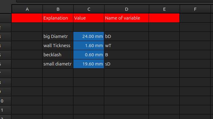
Since I already had a rough idea of what kind of eye I wanted to design and approximately what dimensions I would need, I first created a Spreadsheet(workbanch -> Spreadsheet -> New Spreadsheet) and entered the main parameters.
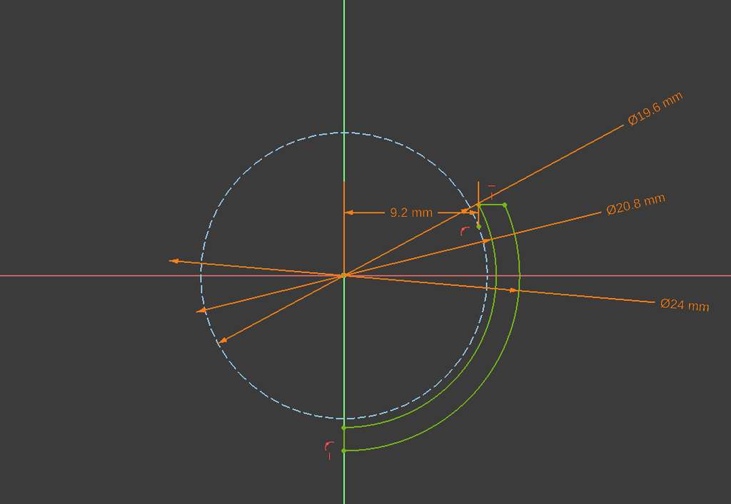
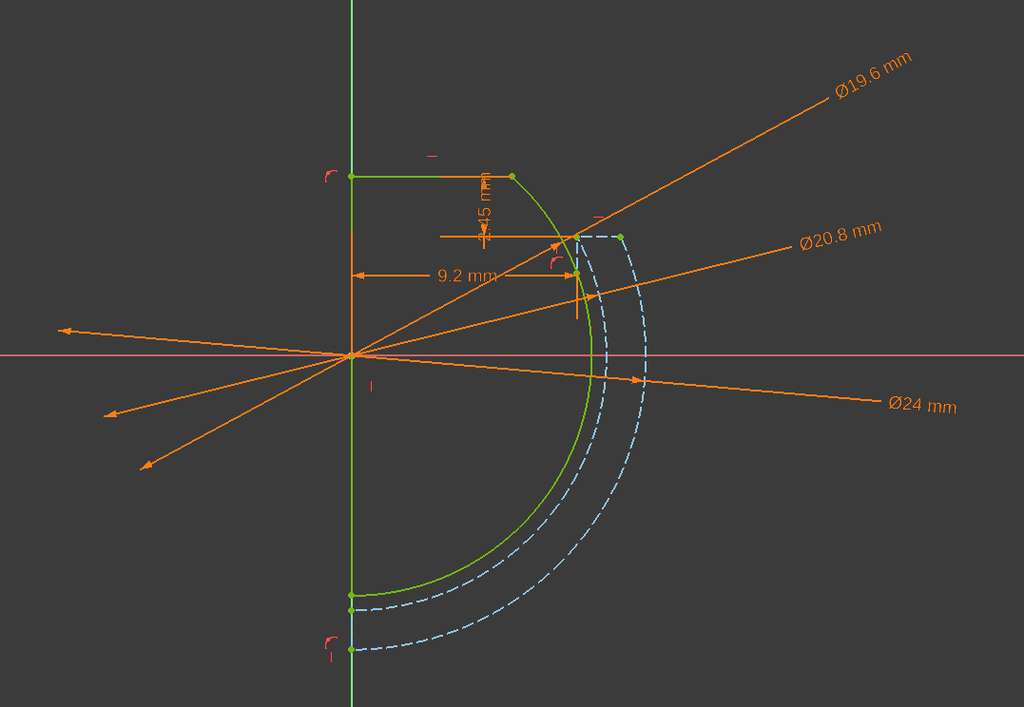
Then I created a Sketch, where I drew an arc using the Arc From Center tool. After that, I created a second arc offset from the first one by the Wall Thickness parameter. I then connected the open ends of the two arcs. After that, I used the Revolve tool to create the solid by revolving it around the Y-axis.
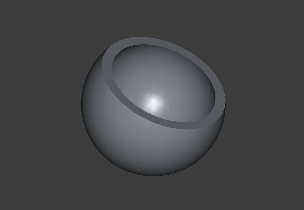
Next, I drew another profile with a smaller diameter and made it slightly longer than the previous larger profile. Once again, I used the Revolve tool and revolved it around the Y-axis.
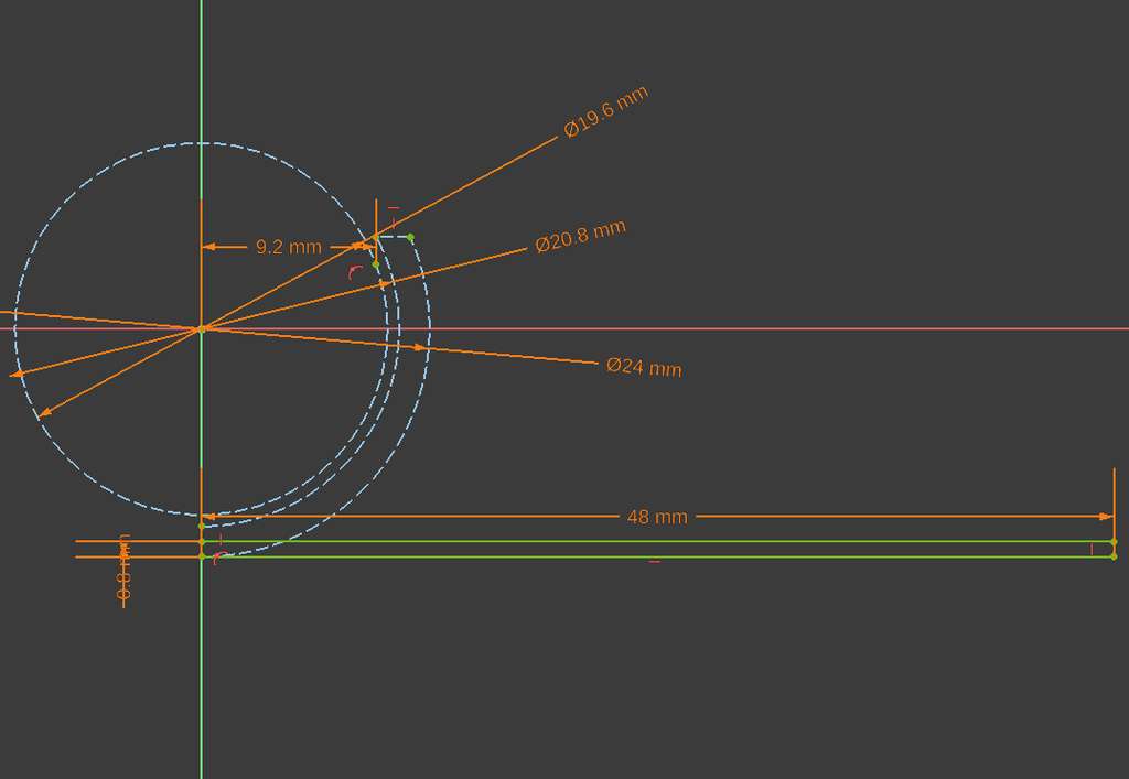
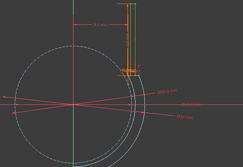
Then, starting from the bottom, I drew a line with a diameter twice as large as the previous one and gave it a height equal to the Wall Thickness parameter toward the larger circle. After that, I used the Pad tool and set its width to 3.00 mm on both sides.
Next, inside the cut section of the inner circle, I created a pupil-like shape using two arcs and again used the Revolve tool to revolve it around the Y-axis.
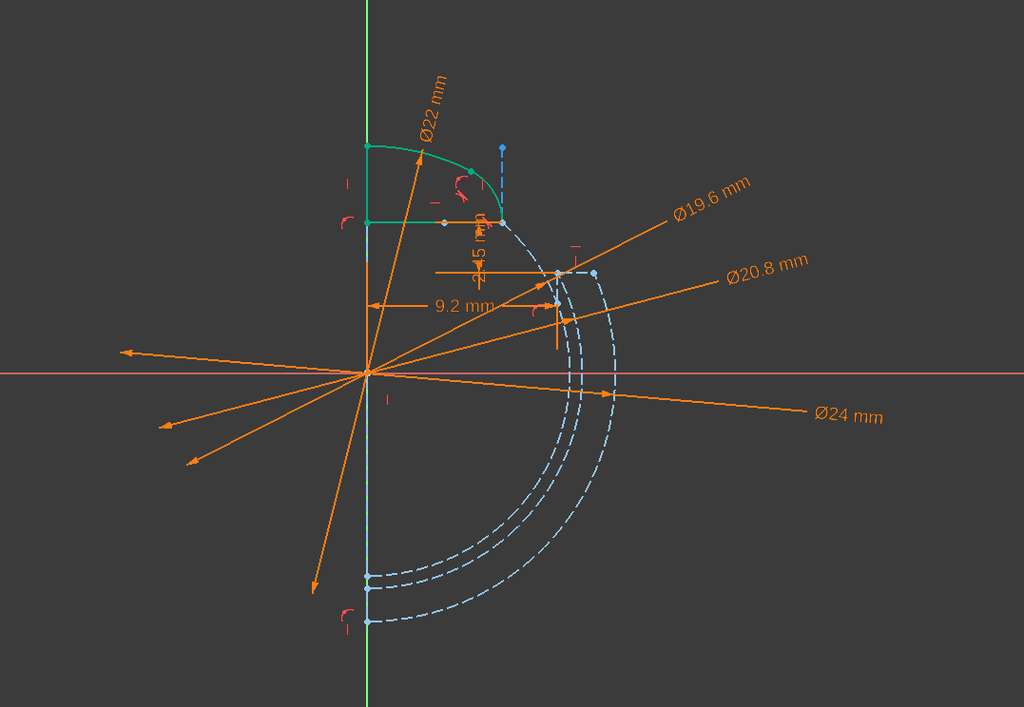
As shown in the drawing above, the distance between the larger and smaller circles is 20.8 / 2 mm − 19.6 / 2 mm = 0.6 mm. This value was determined through experimentation and visual estimation until I achieved the desired result.
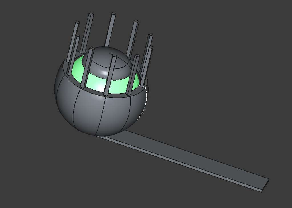
Finally, in the last step, I created the eyelashes. I modeled a single eyelash, gave it thickness using the Pad tool, and then used the Polar Pattern tool. I set the Angle to 360° so it would repeat around the entire circle and set the Occurrences parameter to 10, creating ten evenly spaced eyelashes.
Slicing - Orca Slicer
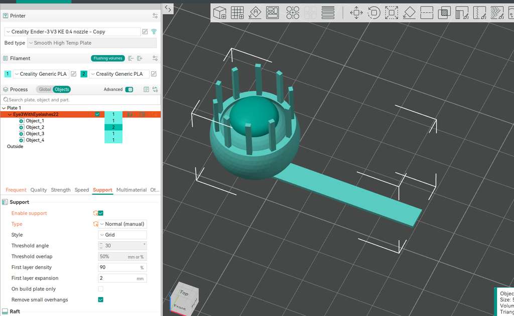
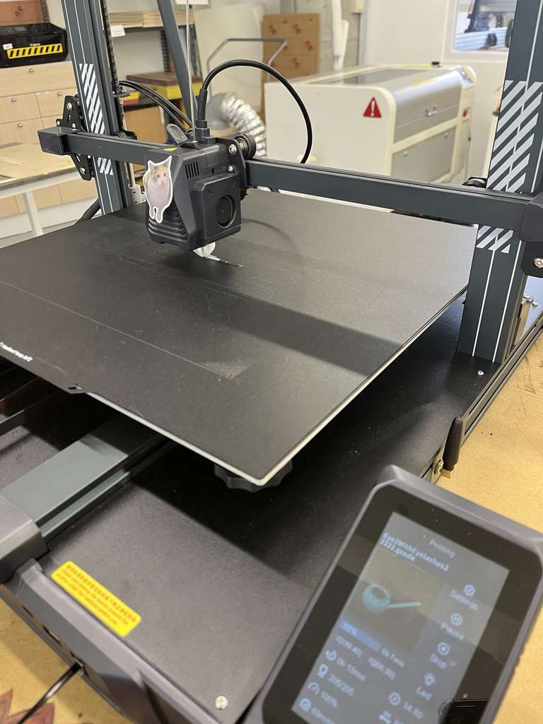
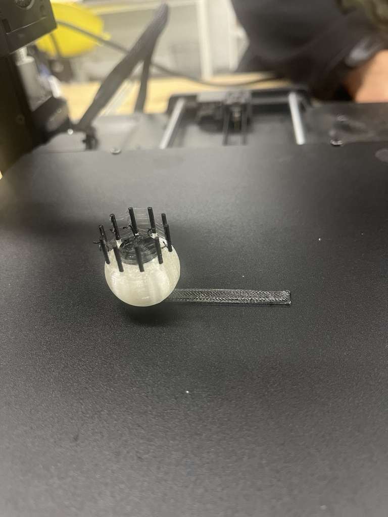
We had already done several experiments during the Group Assignment, and since I already knew how to use OrcaSlicer, I decided to run a few more experiments. Since this was my first time printing such a model, I conducted several experiments to determine the required amount of support. Initially, I tried printing without supports, assuming the gap was small enough to separate the parts manually. After this attempt failed, I printed the model again with supports.
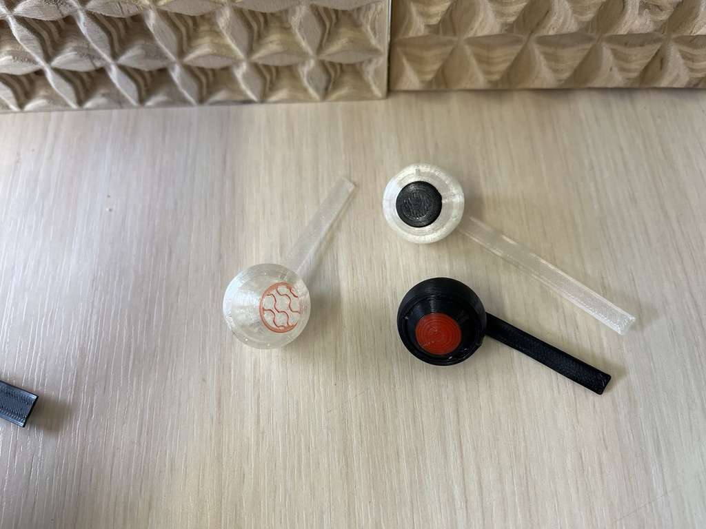
After these experiments, my instructor showed me how to achieve multicolor results using a single-color printer. This process was very interesting, and I am happy to have learned this new technique. Thank you, Areg jan!
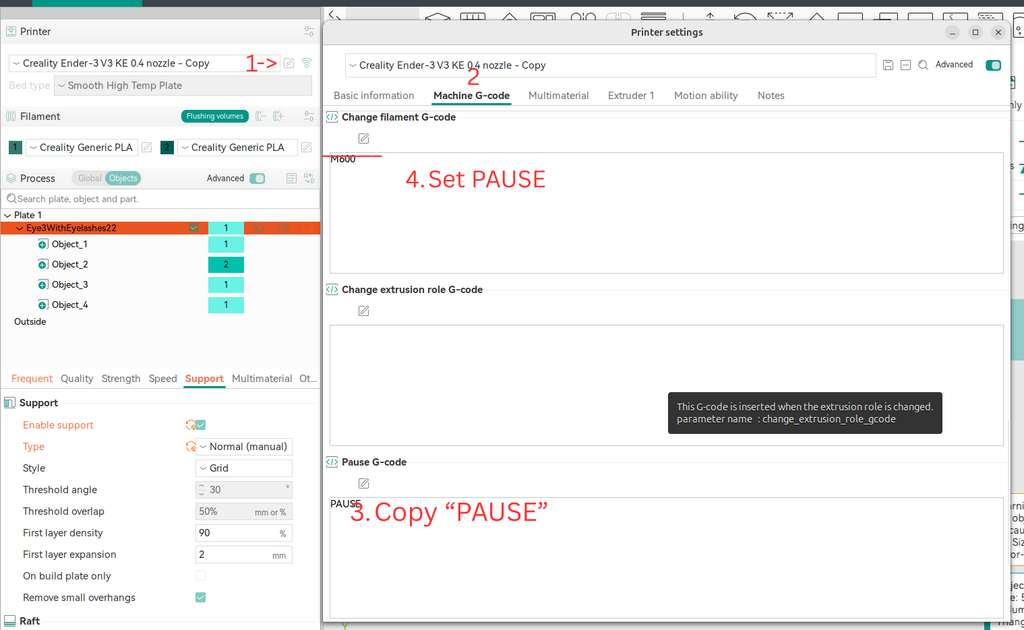
Below is the process showing how I add a new filament and pause the print at a specific layer to change the filament color.
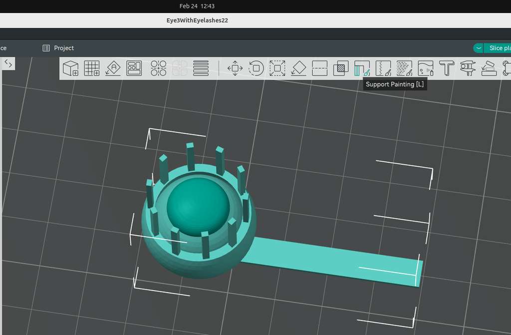
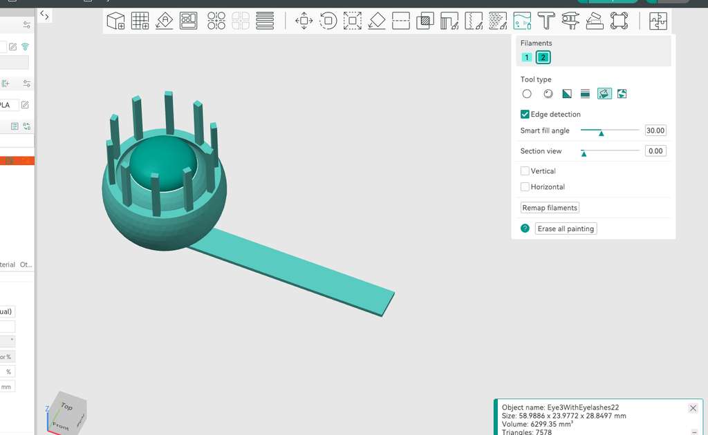
First, I imported the eye model that I created in FreeCAD into the OrcaSlicer environment.
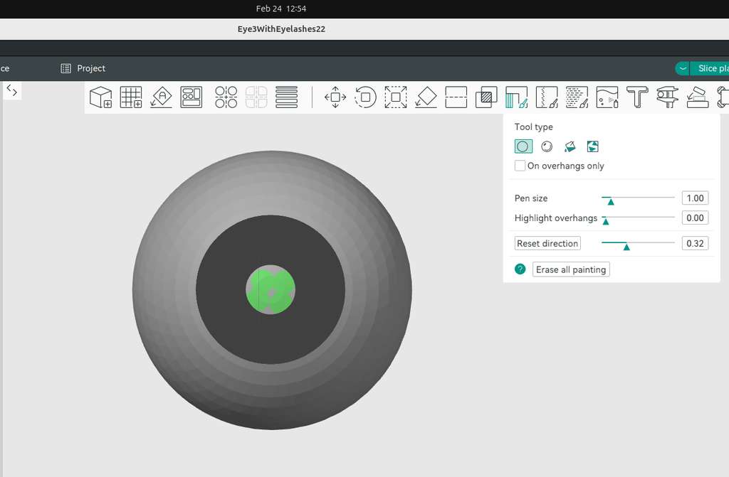
Using the Support Painting tool, I set the object to the bottom view and adjusted the direction to see the inner part of the model, so I could place supports under the internal object.
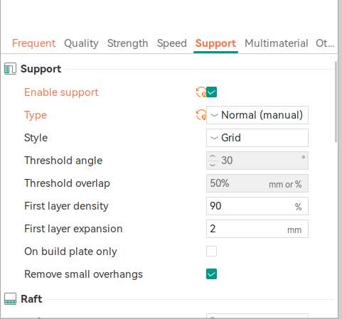
Then, in the Support settings, I enabled supports and selected the type as Normal (Manual).
After slicing, I moved through the layers to check and make sure the supports were placed correctly and in the right positions(Support interface).
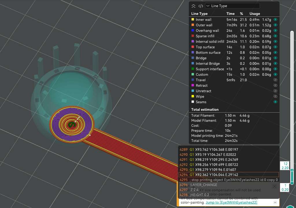
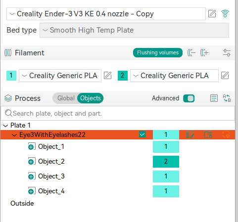
Next, I added a new filament color, assigned it to the required part of the model, and used it to set a pause for filament change during the print.
250°C.
3D Scanning
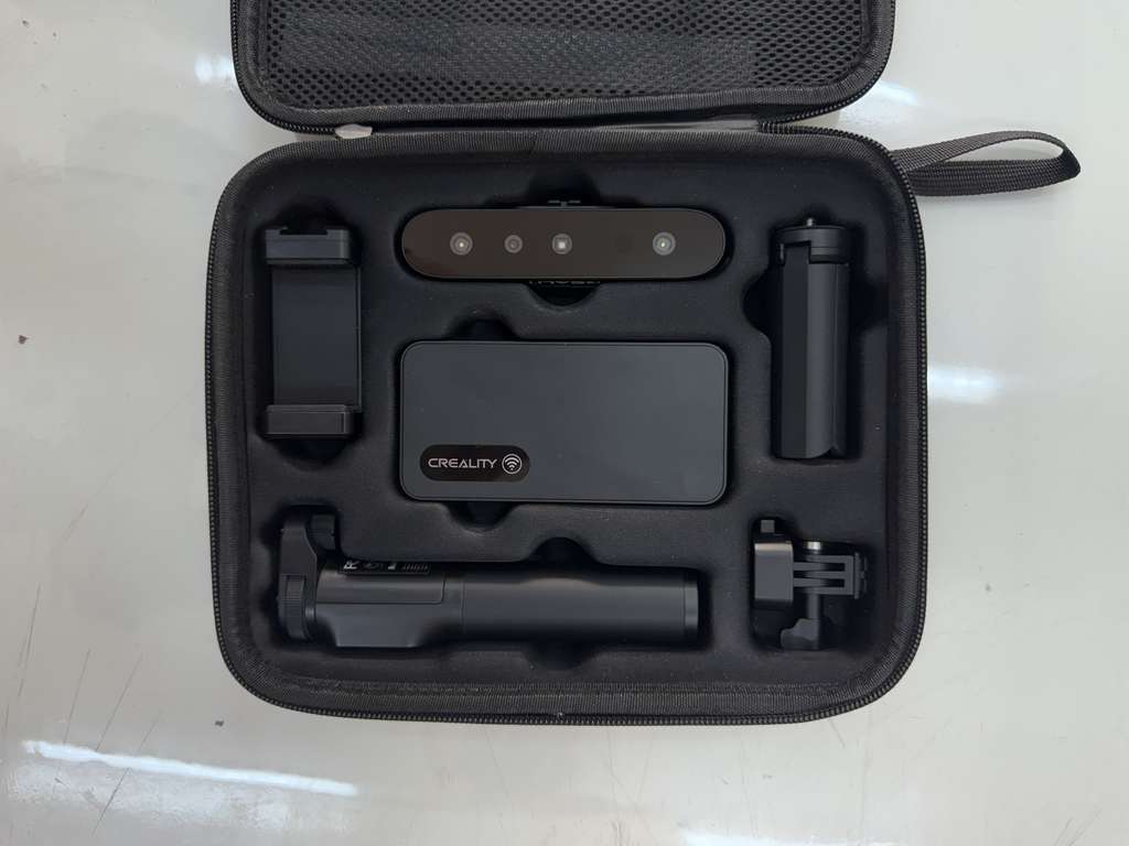
CR-Scan Ferret Pro 3D Scanner
We also studied and understood the process of obtaining 3D models using a scanner, which will later be prepared for 3D printing. We used the CR-Scan Ferret (Pro).
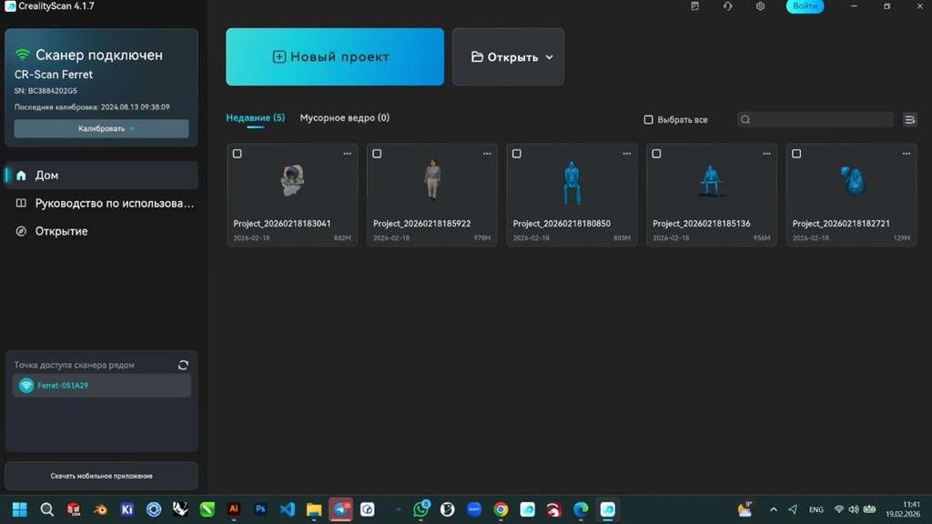
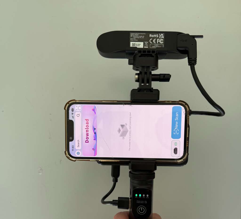
Setting up the scanner
We opened the CrealityScan scanning software on the computer and the phone, connected the scanner to the system via networking.
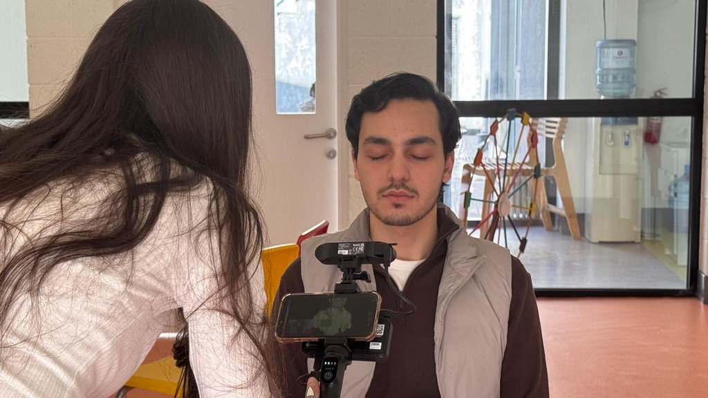
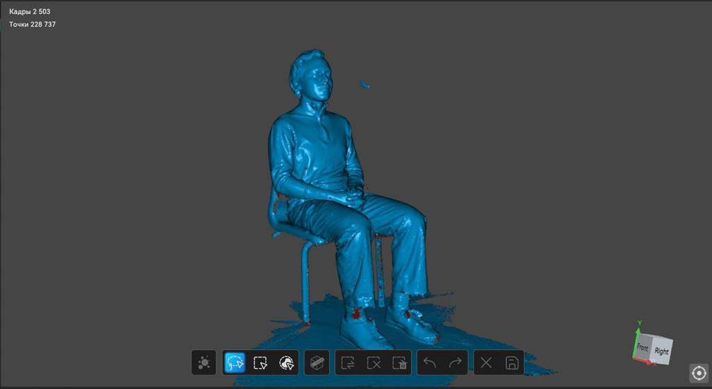
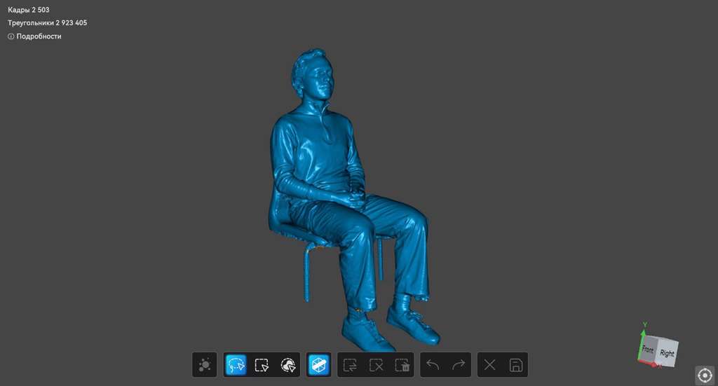
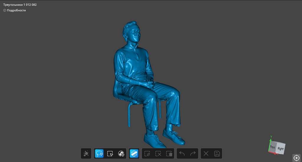
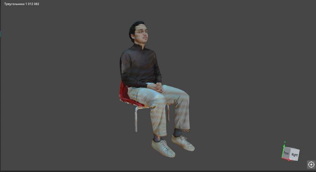
Scanning Hrach
Post Processing - CrealityScan
And I started scanning one of my groupmates. Here are the processing stages of the model.
Next, we performed filament tests for both PLA and PETG materials using three different printers in order to print our scanned models with maximum accuracy. After dividing the work, I conducted the tests using the Elegoo Neptune 4 Max (0.4 mm nozzle).
Print Scanned Model
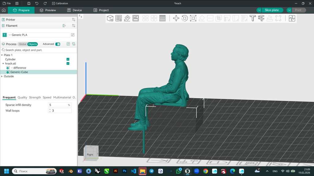
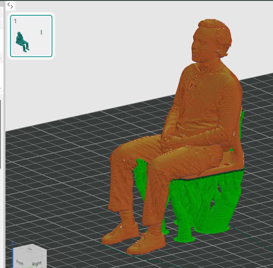
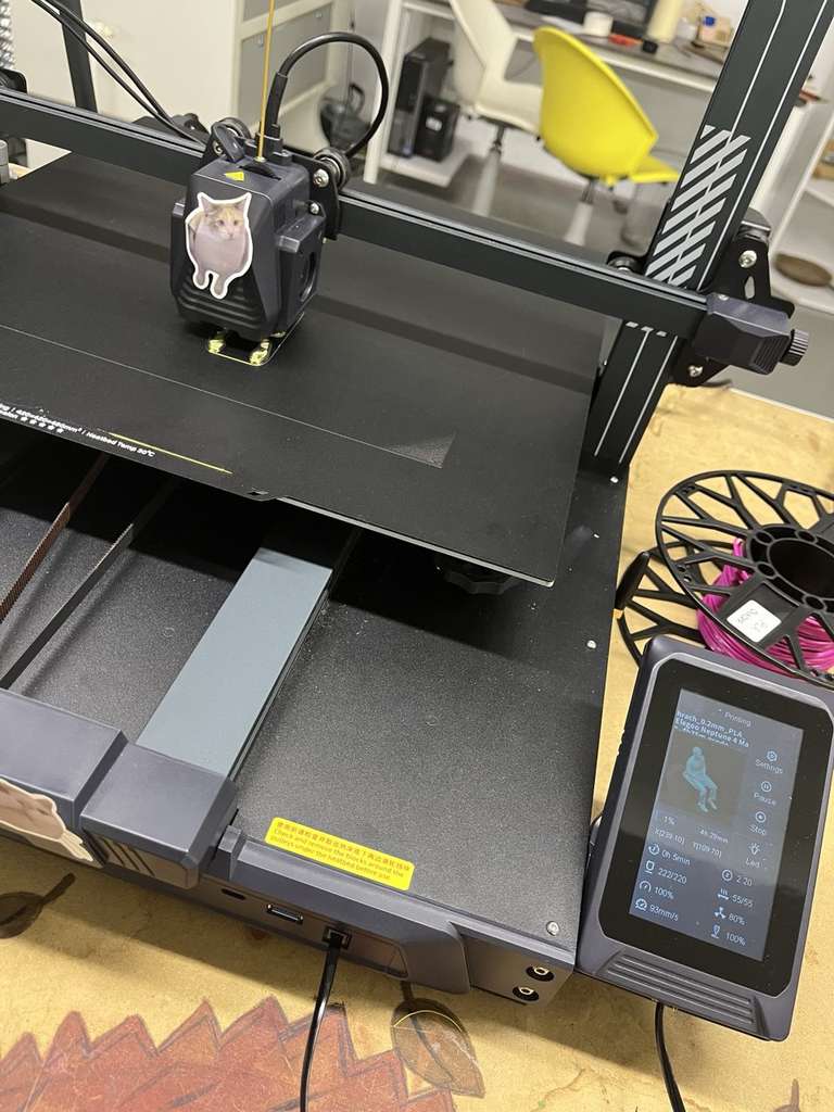
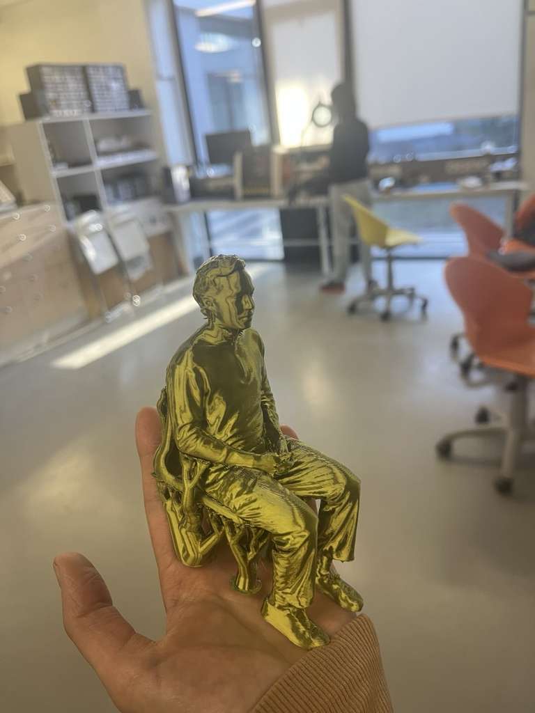
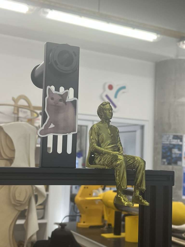
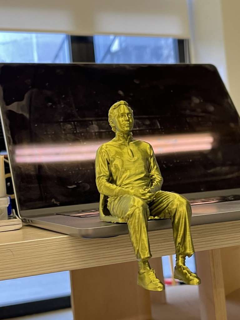
Finally, it was time to print my groupmate’s scanned model. I printed it again using the Elegoo Neptune 4 Max with PLA filament.
Since the chair was not properly captured during the scanning process, I removed the unnecessary parts. Instead of the original chair, I added support structures, which also created an interesting chair-like design. These supports can be removed later, allowing the model to be placed in any desired position 😊
The PLA filament spool recommended a nozzle temperature of 190–220°C and a bed temperature of 45–60°C. Based on these recommendations, I printed my model using a 220°C nozzle temperature and a 60°C heated bed temperature, which produced good layer adhesion and an overall satisfactory print quality.
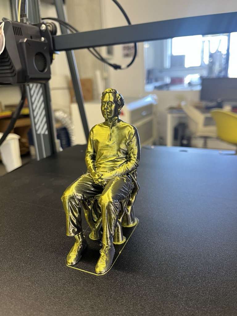
My groupmate Hrach Barseghyan
This week, I focused on 3D scanning, model processing, and 3D printing calibration. I prepared models in OrcaSlicer, and tested different filaments (PLA, PETG) and printers.
I performed calibration tests including temperature, Max Flowrate, and the Mini All-in-One test, experimented with supports and multicolor prints, and designed parametric models in FreeCAD, such as movable eyes for my final project robot-car.
Week 5 strengthened my understanding of the full digital fabrication workflow and gave me confidence to apply these skills in future projects.
Individual assignment
- Eye 3D Model .3mf
- Eye 3D Model .FCStd
- Hrach's scanned model - drive link (This is a Google Drive link because the file is too large to upload directly) .
AI prompt:
“AND another image when she finished week 5.”