
Week 3

AI prompt:
“Now I need to create an image where she is in FreeCAD, drawing with the parametric stand design(board where I have set 3 joints first for the decorative tree, another two for the stand joints). And also in OpenSCAD, I drew a parametric random maze(there I have a board with nets and walls for the maze, these walls are generated randomly). And also I want to use a vinyl cutter for cut tree life, and a mini sticker like Toothless”
Computer-Controlled Cutting
Laser Cutting
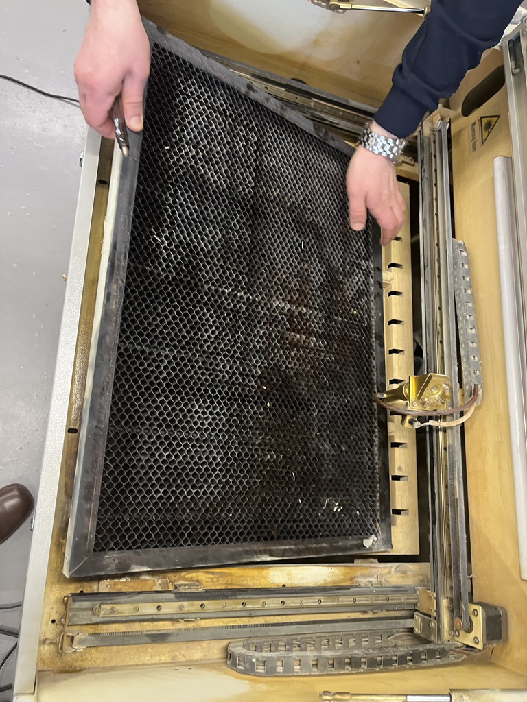
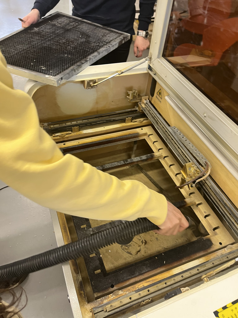
This week, we started by studying the rules for working with the laser cutter.
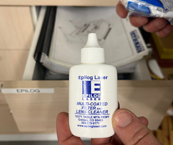
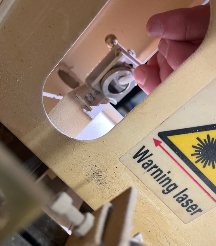
Our instructor introduced us in detail to the safety rules. After understanding the information well, my classmate Hrach and I carefully cleaned the laser cutter. Here are the photos.
I would also like to mention that at the end of the session, I received a birthday surprise from the wonderful FabLab Dilijan team. Thank you very much for the congratulations!
During the group assignment, I learned how to safely operate the laser cutter and how machine parameters influence fabrication quality. By testing different cutting settings and measuring the kerf, I understood that laser cutting is not only about creating geometry but also about compensating for material loss to obtain accurate press-fit assemblies. I also learned how RDWorks uses colored layers to assign different cutting and engraving operations, and how selecting appropriate speed, power, and pass settings affects the final result.
In RDWorks, vector operations are assigned to layers according to their color. The kerf test vectors were assigned to the red layer, which was configured as a cutting operation. Each color layer can have independent speed, power, and pass settings, making it easy to test different parameters.
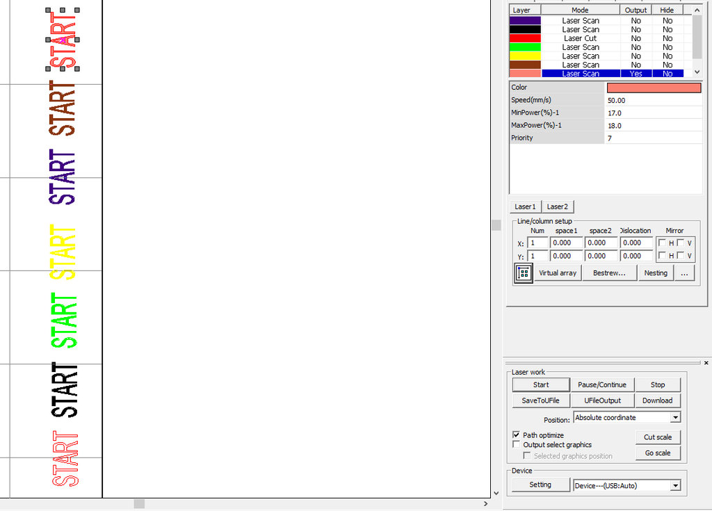
To clearly present the best results from our group tests, I will use two different colors.
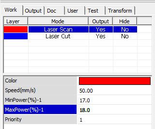
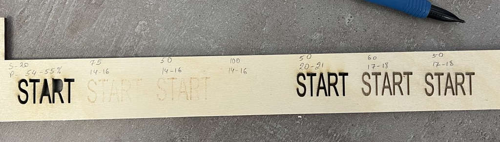
Laser Scan – We use blue to indicate the Laser Scan operation. In RDWorks, any object colored blue will be processed as a Laser Scan. The parameters we found to give the best results are:
- Speed: 50 mm/s
- Min Power: 17%
- Max Power: 18%
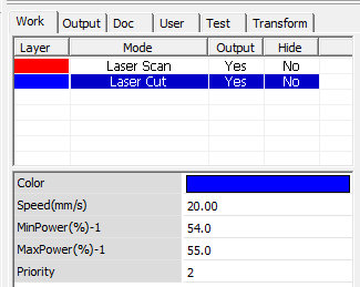
Laser Cut – We use red to indicate the Laser Cut operation. In RDWorks, any object colored red will be processed as a Laser Cut. The parameters we found to give the best results are:
- Speed: 20 mm/s
- Min Power: 54%
- Max Power: 55%
vinyl cutter
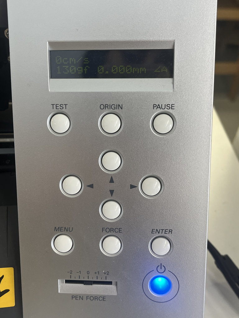
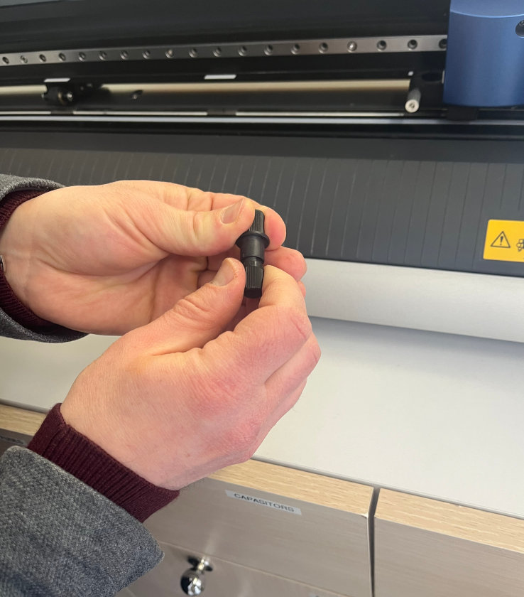
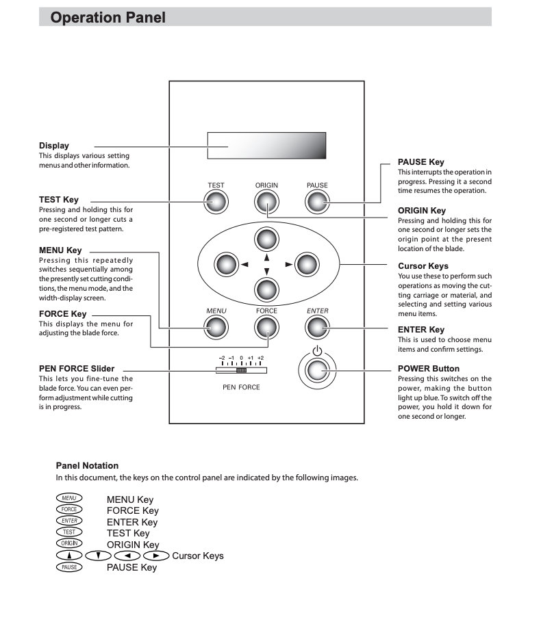
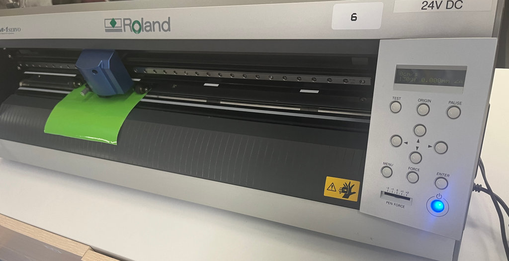
First, we studied how the vinyl cutter operates. We learned how to start the machine and how to adjust the speed and cutting force. I only modified the cutting force depending on the thickness of the material, humidity, and other factors, which varied between 130–150 gf.
He was responsible for creating a parametric test card that we would use to test and evaluate the laser cutter parameters. This card helps us understand how different settings affect the cutting results for specific materials.
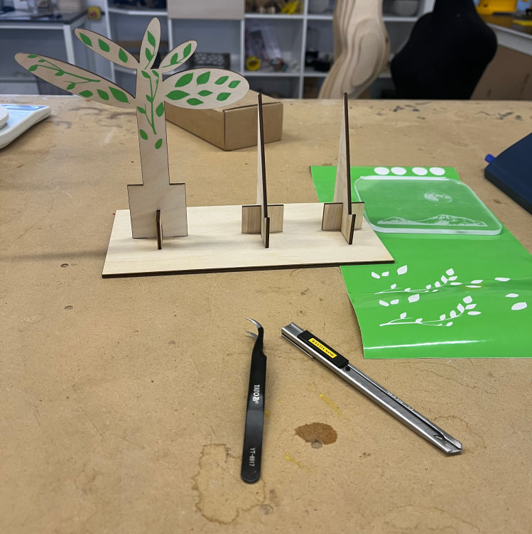
My task was to design and create a stand where the card would be placed. I also added a decorative tree (if it can be called a tree 😊) to give the stand a more unique and aesthetically pleasing appearance.
I will present my hand-drawn sketch. At the end, I will also provide the sketch.
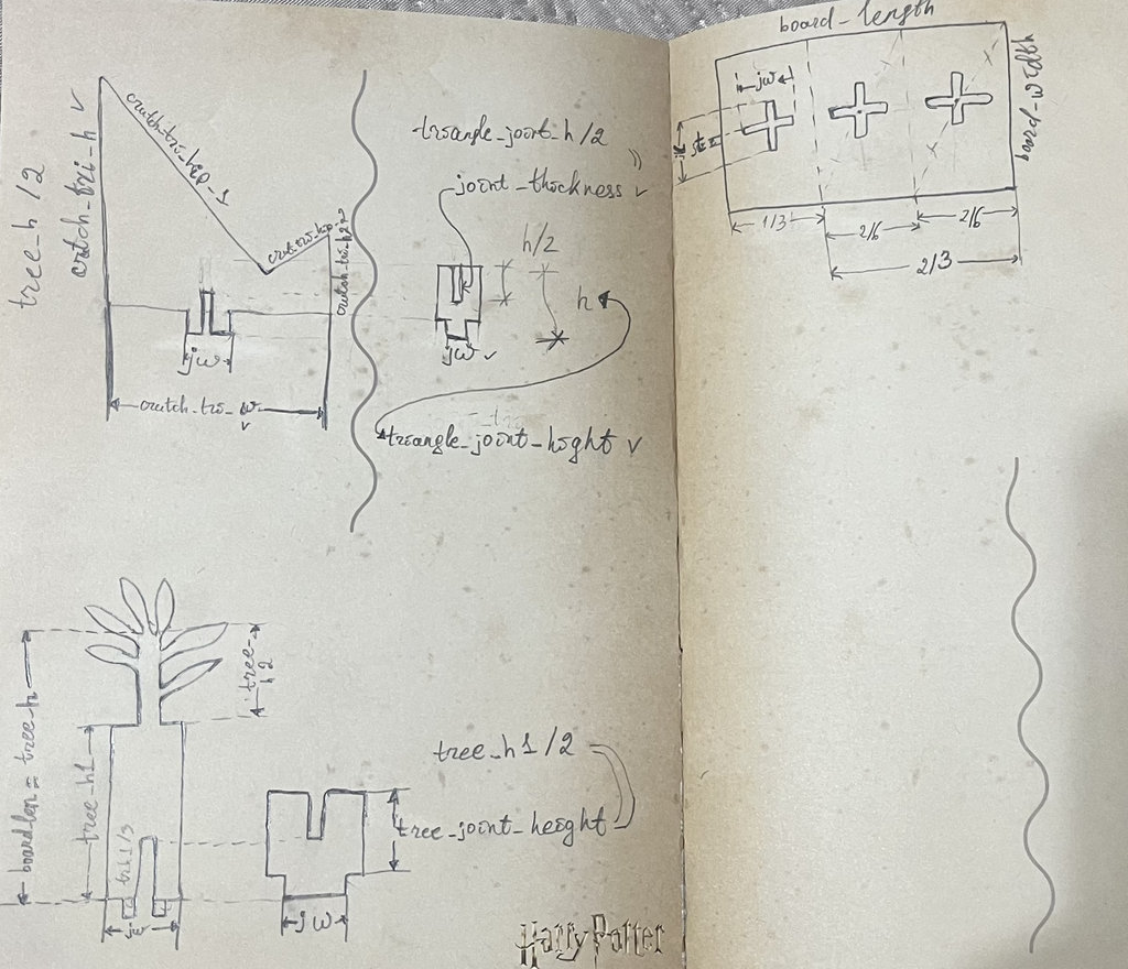
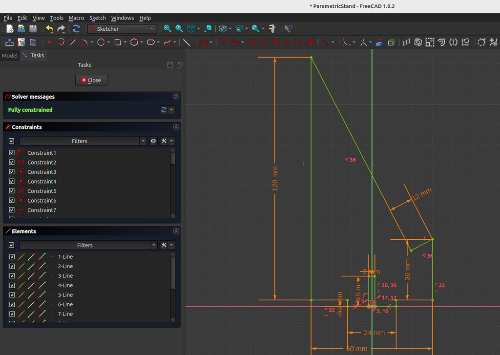
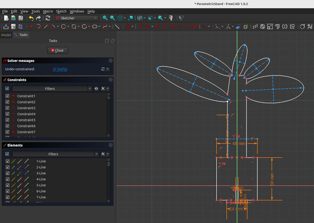
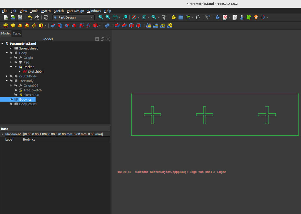
Now I will present the stand that I designed in FreeCAD. After creating the hand-drawn sketch, it became clear which variables were necessary to create a fully parametric stand with interconnected parameters.
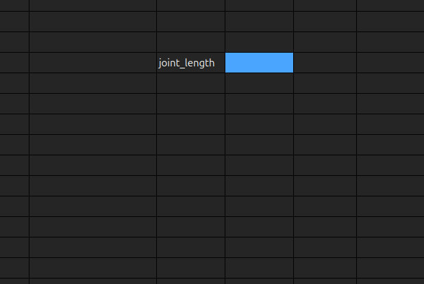
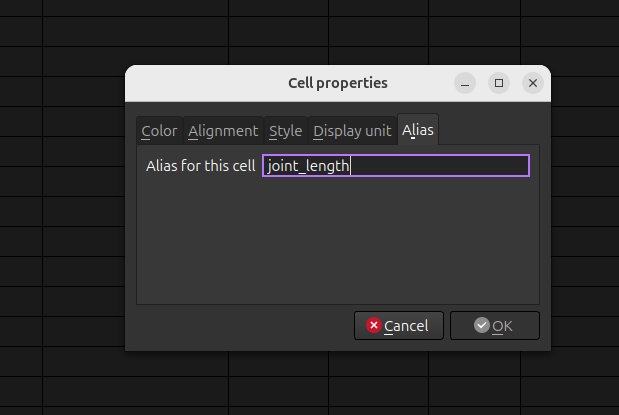
First, I created a Spreadsheet. In any selected cell, I assigned a name or description to the variable that I wanted to create.
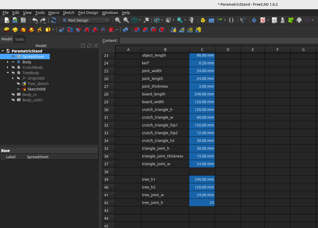
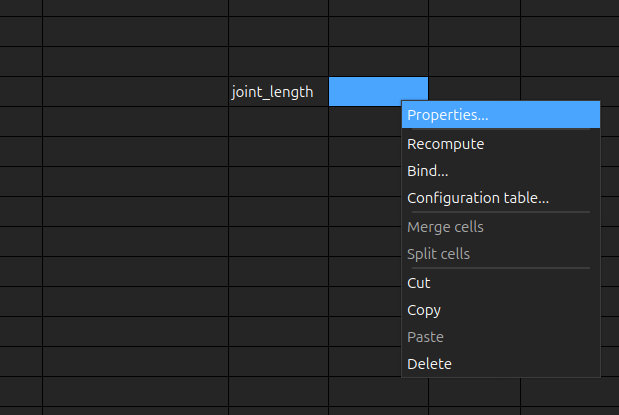
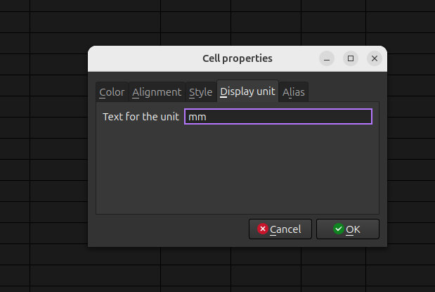
Then, in the adjacent cell, I defined it as a parameter-containing variable. To do this, I performed the following steps:
All line lengths shown in the drawing are interdependent, and I organised them using a spreadsheet with corresponding values.
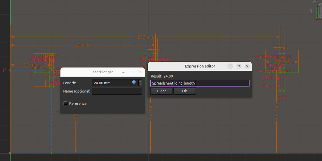
After that, I was able to assign the variable name to any part of the design, and its value was automatically read from the Spreadsheet.
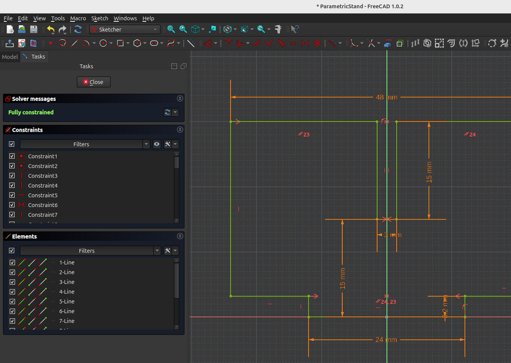
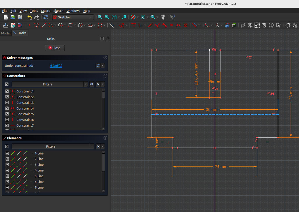
And here are the sketches of all the parts used to create the stand.
Then, to move from FreeCAD to laser cutting, I need to export each sketch from FreeCAD as an .svg file. This is because the software used to operate the laser cutter is RDWorks, where files are imported in .svg format.
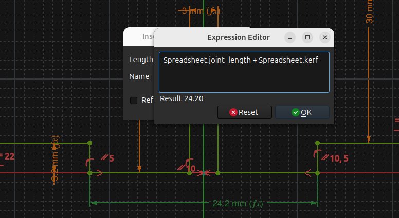
Let me demonstrate how I use the kerf value to achieve a precise fit using the example of attaching the tree to its base.
First, I'll start with the tree base. Since I want the part of the tree that fits into the base to have a final width of 24 mm, I set its width to 24.2 mm in the design. Because the kerf is 0.2 mm, after laser cutting the final width becomes exactly 24 mm.
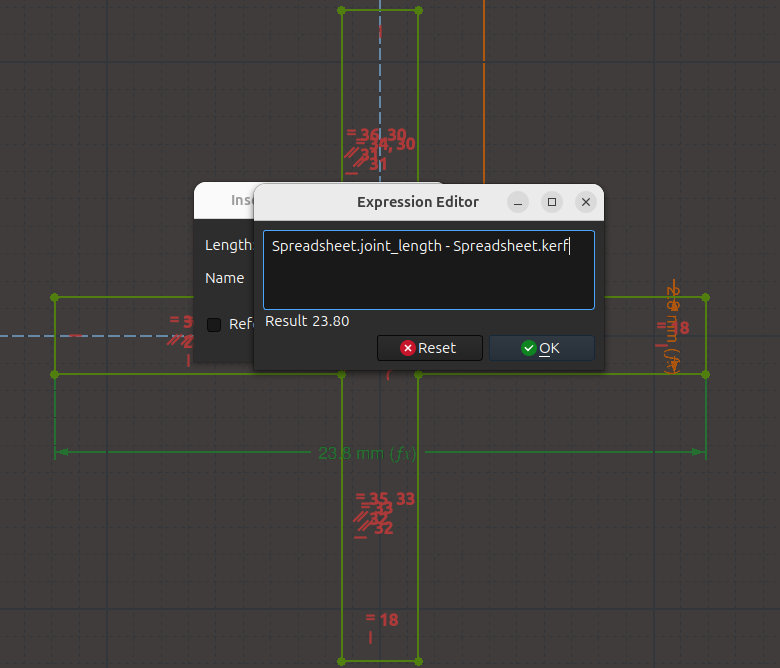
Now let me show the calculation for the slot where the tree base will fit.
Since the tree base is 24 mm wide after cutting, the slot also needs to end up being 24 mm wide. Therefore, I design the slot with a width of 24 - 0.2 = 23.8 mm.
To explain this more clearly: if I make the slot 23.8 mm wide in the design, then after laser cutting, the kerf causes the slot to become wider by approximately 0.2 mm. As a result, the final slot width becomes 24 mm, allowing the tree to fit accurately into the base.
One of the most important lessons I learned while working with the laser cutter is how to compensate for kerf in press-fit designs. If a feature is designed to fit into a slot, I model the tab as the nominal dimension plus the kerf value. The matching slot is designed as the nominal dimension minus the kerf value. This simple rule compensates for the material removed by the laser and produces accurate, tight-fitting joints.
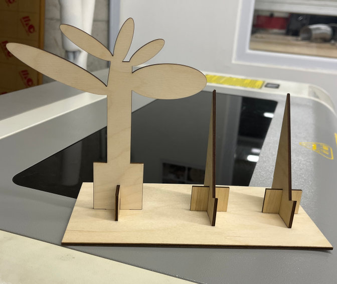
The stand was cut using a Laser Cut operation with a speed of 20 mm/s and 54–55% power.
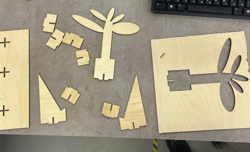
Here are photos of the stand.
vinyl cutter
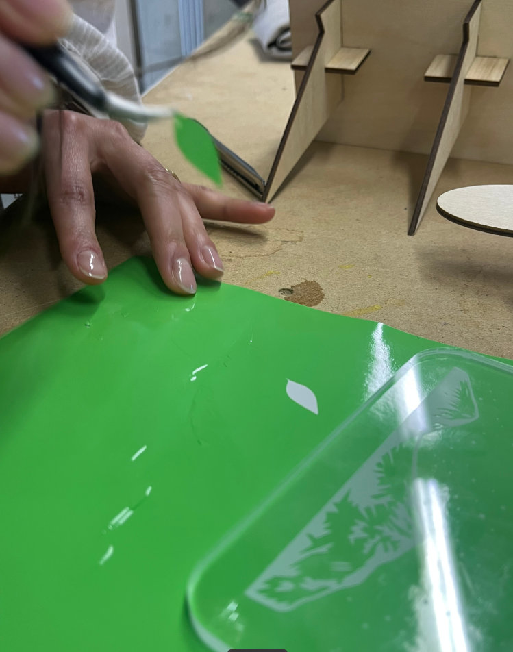
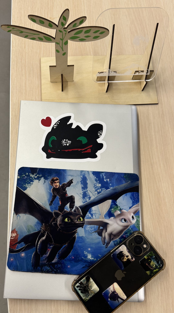
For the vinyl cutter assignment, I planned to cut decorative leaves for the stand design. I also planned to create a sticker shaped like Toothless.
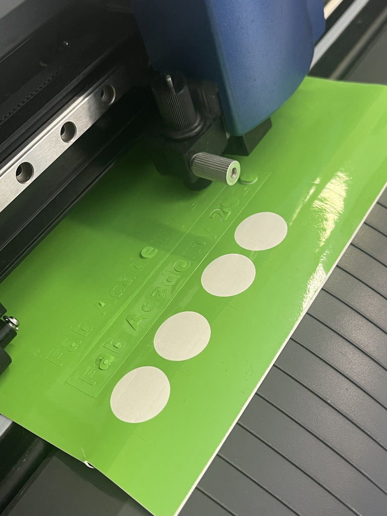
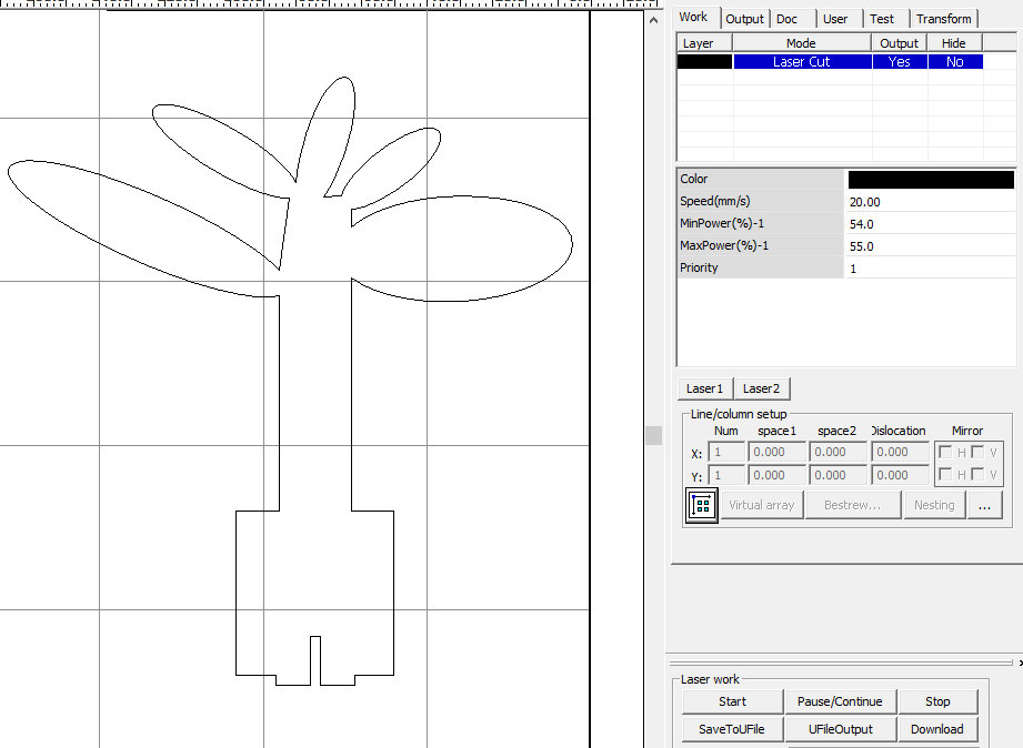
Let’s start with the leaves.
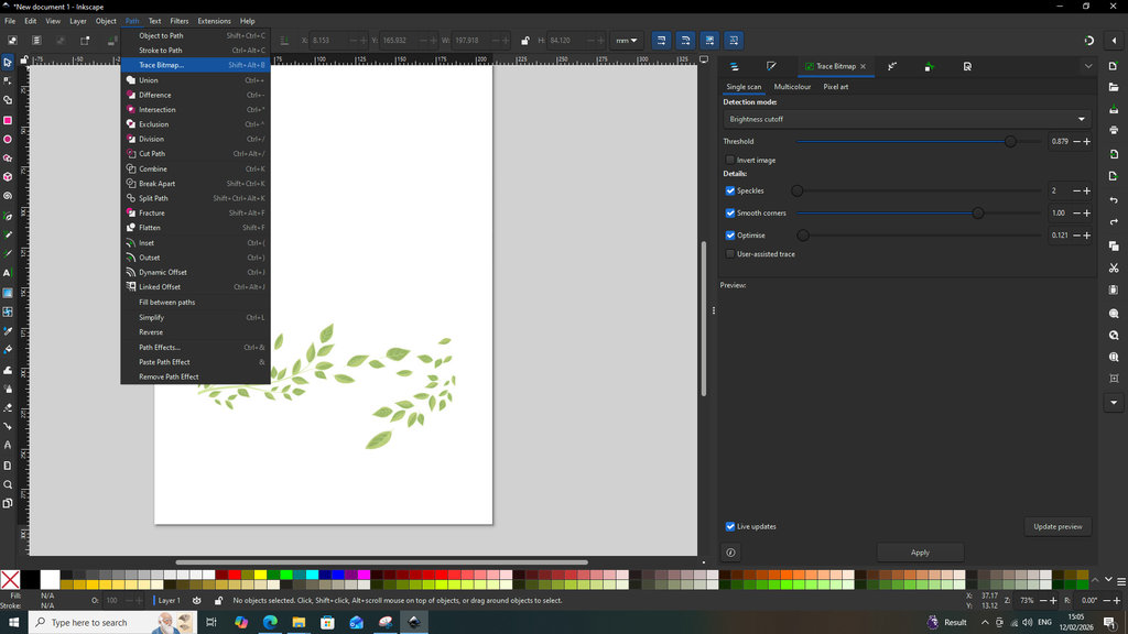
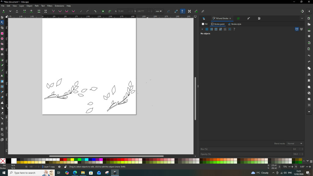
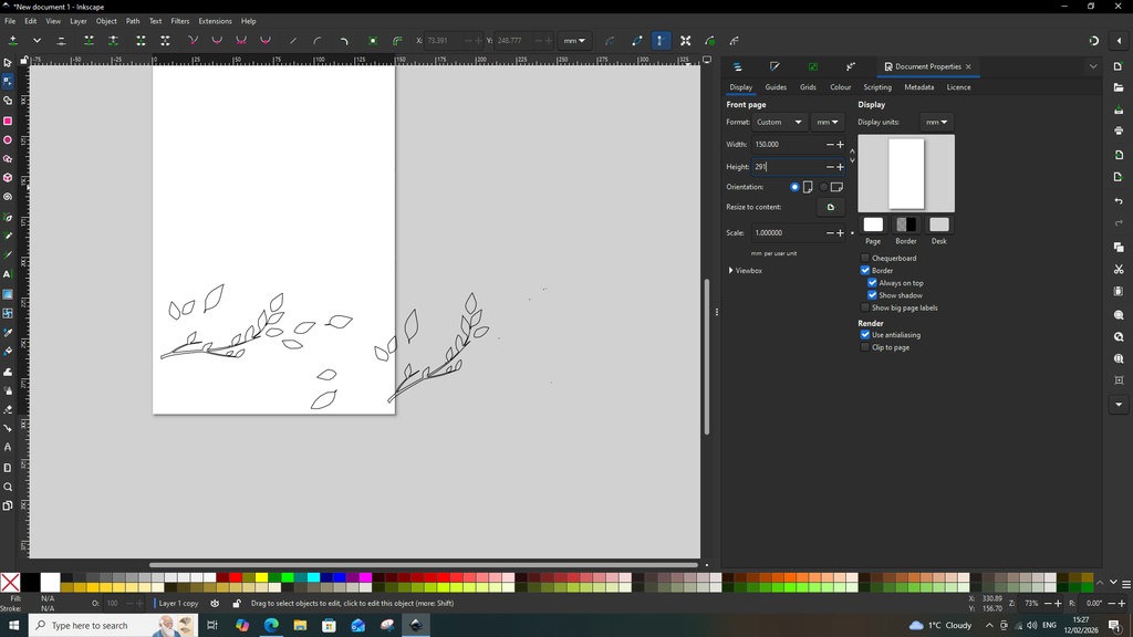
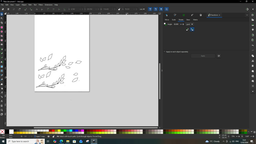
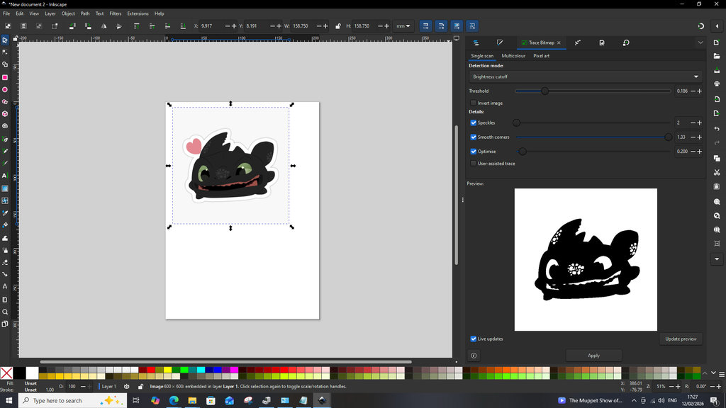
Since the tree decoration on the stand did not visually resemble a tree very well, I decided to attach leaves to it. First, I selected the image that I wanted to place on the tree. The leaf image was also downloaded from the internet using the following link. Then, using the Trace Bitmap tool, I converted the image from raster format to vector format.
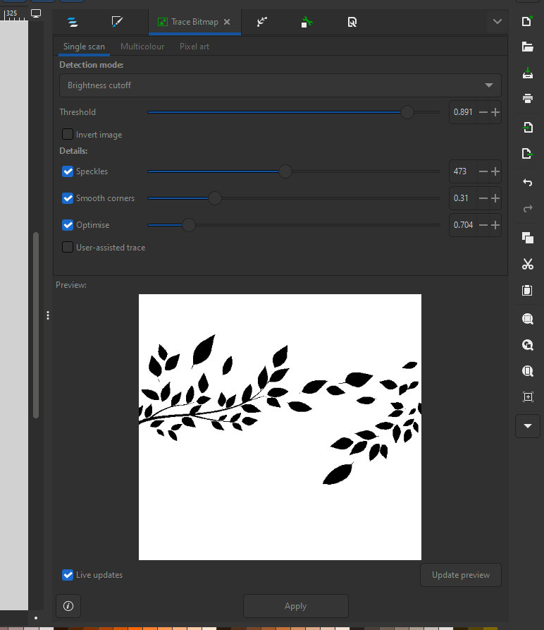
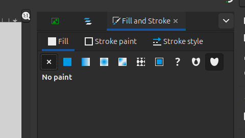
After that, I made the following adjustments in the Fill and Stroke section.
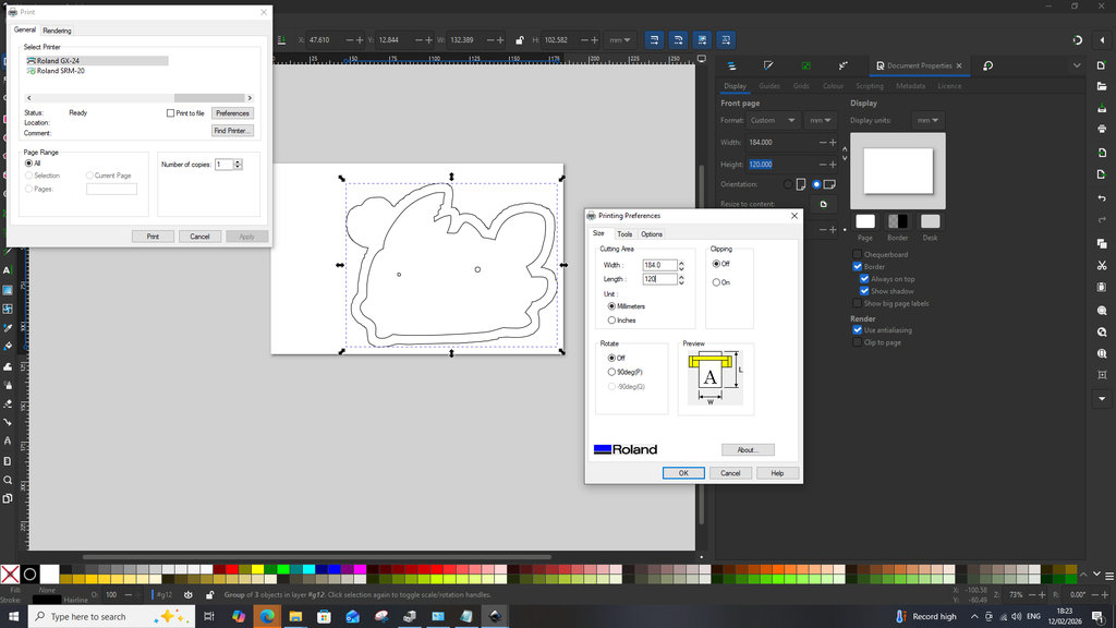
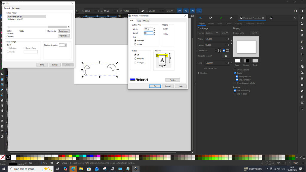
Once I obtained the desired result, I prepared the design according to my paper size. By pressing CTRL + Shift + D, or by navigating to File → Document Properties, I set the width and height values according to the dimensions shown on the vinyl cutter screen after inserting the paper and configuring the machine.
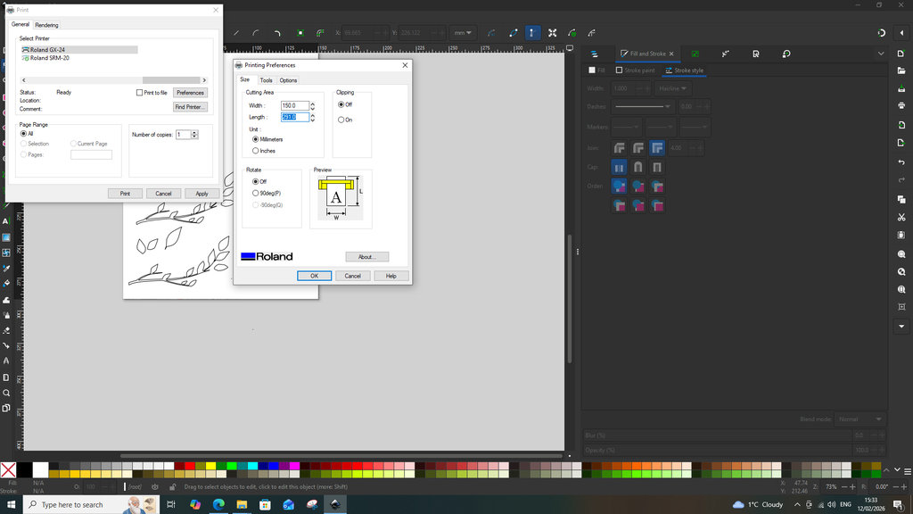
When the file was ready for cutting, I pressed CTRL + P or navigated to File → Print. In the General section, I selected the vinyl cutter name Roland GX-24. Then, in the Preferences section, I manually entered the Cutting Area width and length, making sure they matched the dimensions of the material being cut.
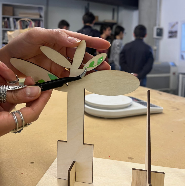
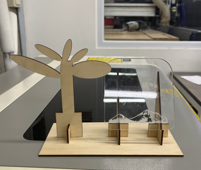
Now it doesn’t really matter whether it looks like a tree or not — the important thing is that it looks beautiful 😊.
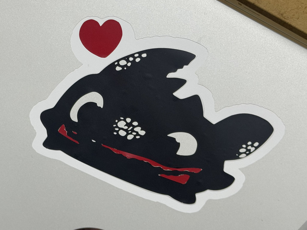
Now I started creating the Toothless sticker.
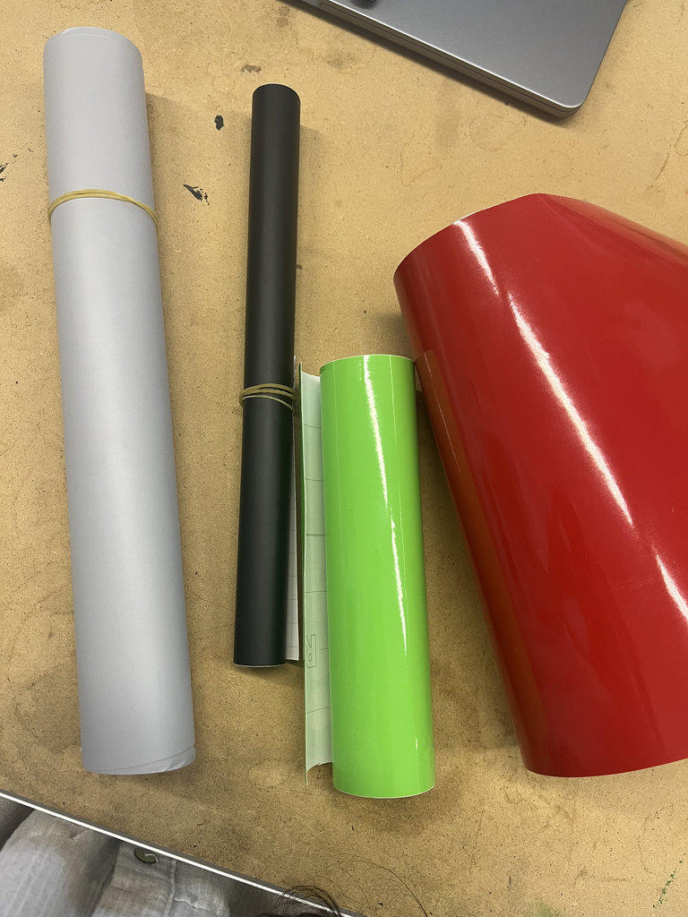
All of the graphics cut with the vinyl cutter were produced using the following settings. I used a cutting speed of 5 mm/s, choosing a slower speed for safety reasons. Since I used vinyl sheets of different colors and thicknesses, the cutting force varied depending on the material. The thickest sheets—the red and gray ones—were cut using 150 gf of force, while all the remaining sheets were cut using 130 gf of force.
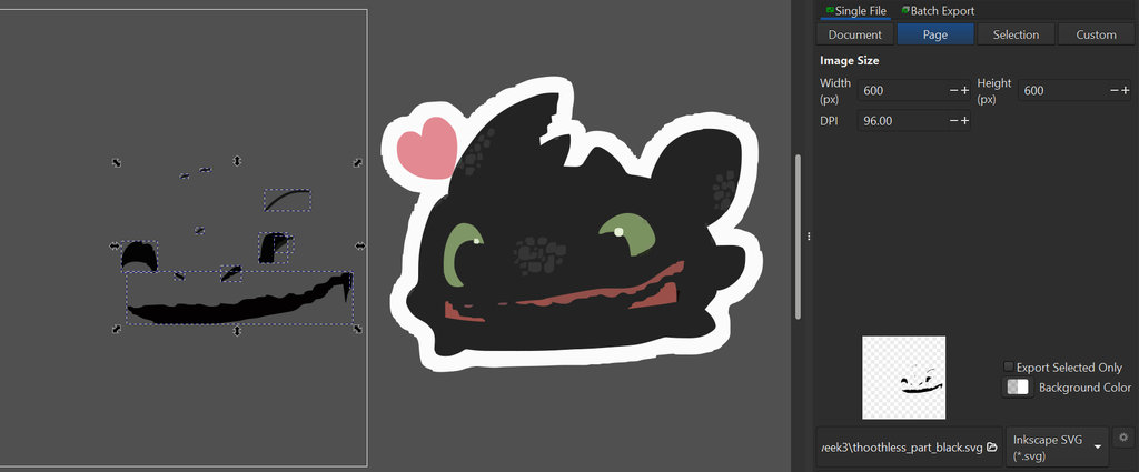
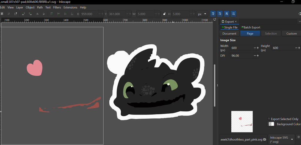
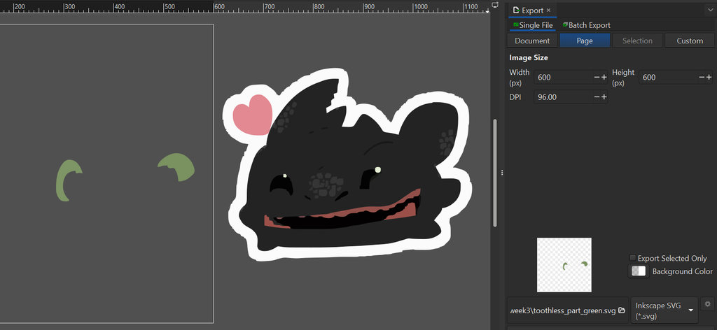
First, I selected the colors of the vinyl sheets that would represent the different parts of Toothless.
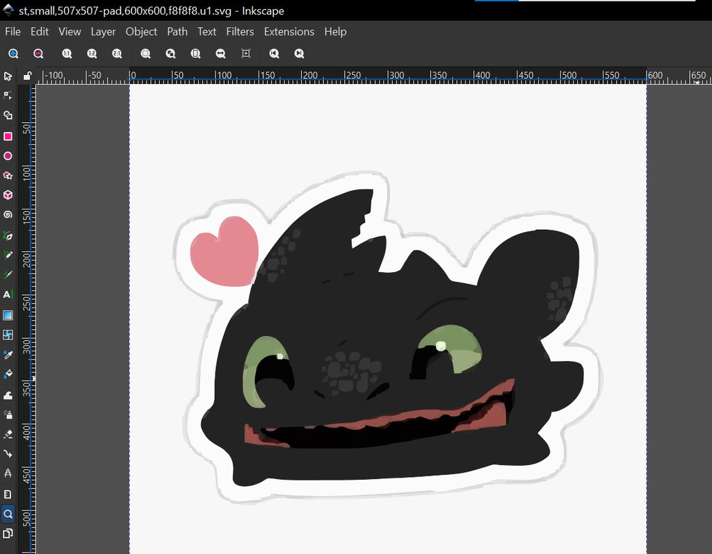
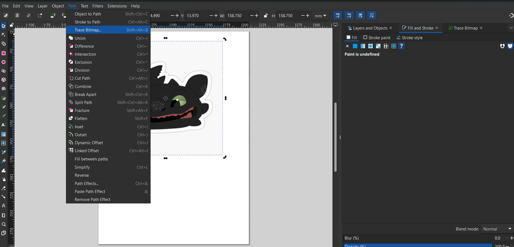
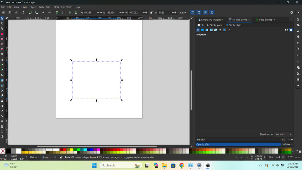
Then, I found the image that I wanted to convert into a sticker. The Toothless image was downloaded from the internet. I imported it into Inkscape and converted it into a vector. Using the Fill and Stroke settings, I performed the same adjustments as I did for the leaves, keeping only the outlines of the image for cutting.
First in Fill and Stroke choose Fill and set it No Point.
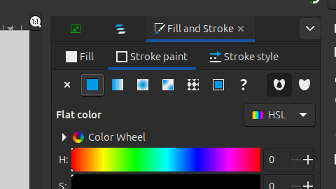
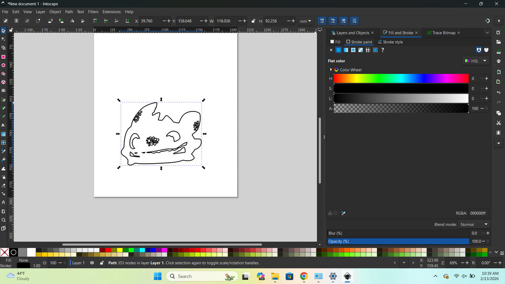
Then Fill and Stroke -> Stroke Point -> Flat Color.
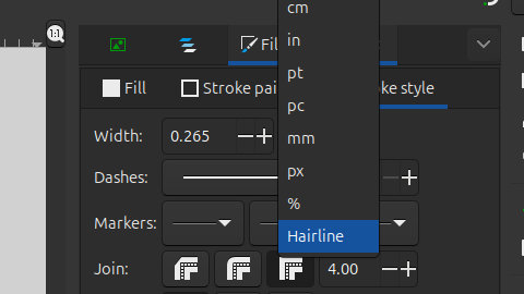
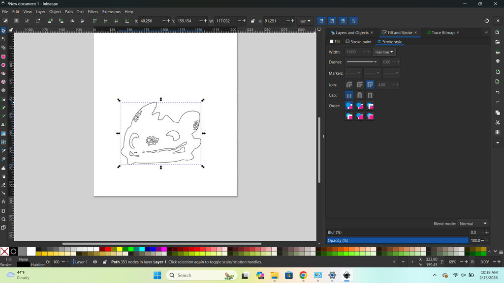
Then Fill and Stroke -> Stroke Style -> Width: Hairline.
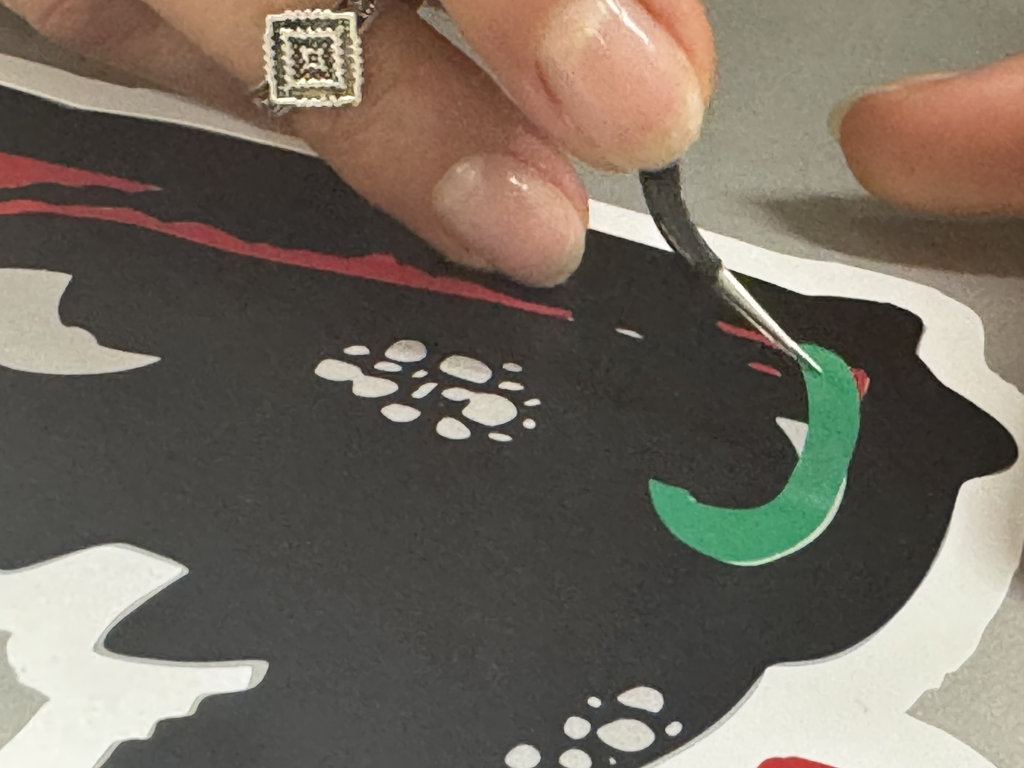
After that, I repeated the same process for each individual part of Toothless that I wanted to cut.
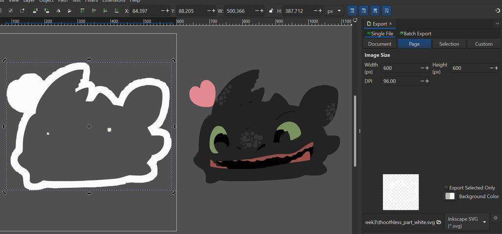
Once all the parts were ready, I assembled them on my notebook (laptop).
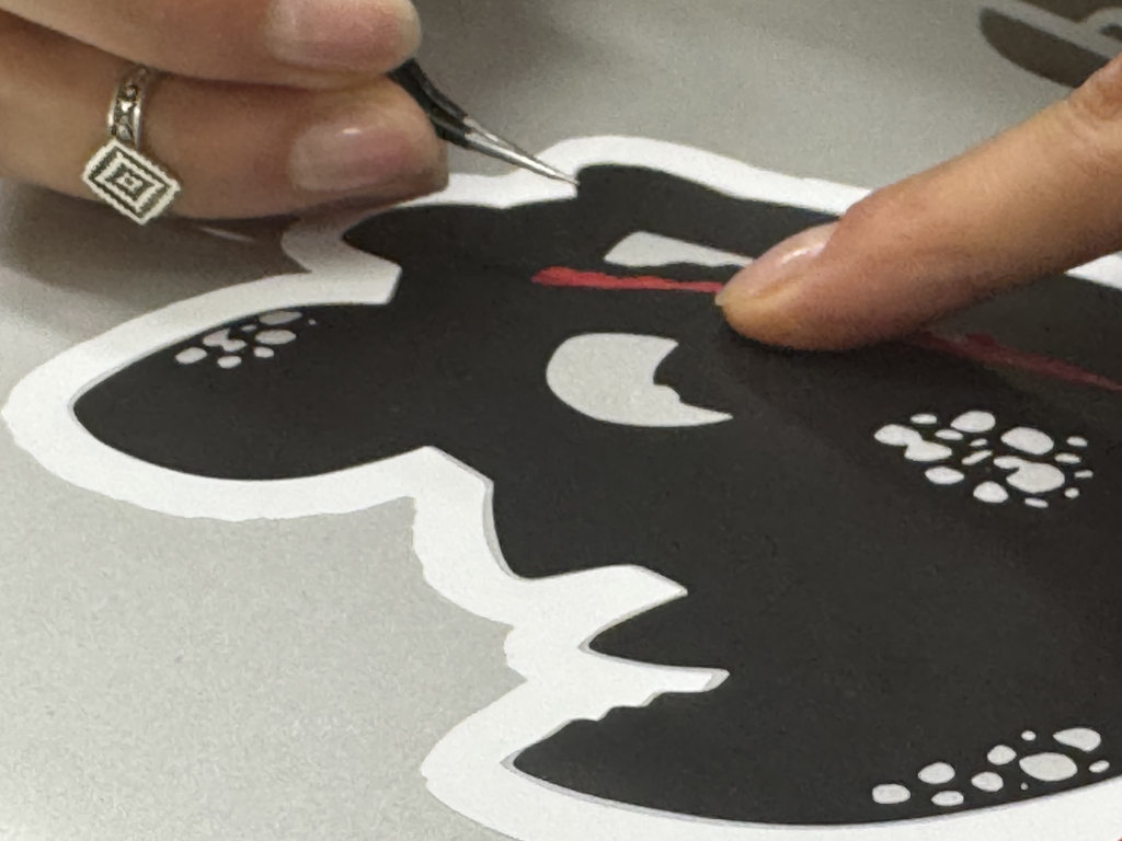
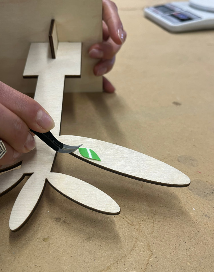
I used vinyl transfer tape to make applying the stickers easier, but I found it more convenient to apply them using only tweezers.
Laser Cutter – Randomized Maze Design in OpenSCAD
Finally, it was time to present my randomized maze algorithm created in OpenSCAD. First, I demonstrated it using a video, and then I moved on to the explanation.
I originally wrote the Game Board code during Week 2. However, since I had manually entered all of the wall position coordinates, I later asked ChatGPT:
"Please convert the array of wall positions that I created into an array that generates the wall positions randomly, and also improve my code."Based on that prompt, ChatGPT optimized the code and replaced the manually defined wall positions with a randomly generated layout while preserving the overall functionality of the game board.
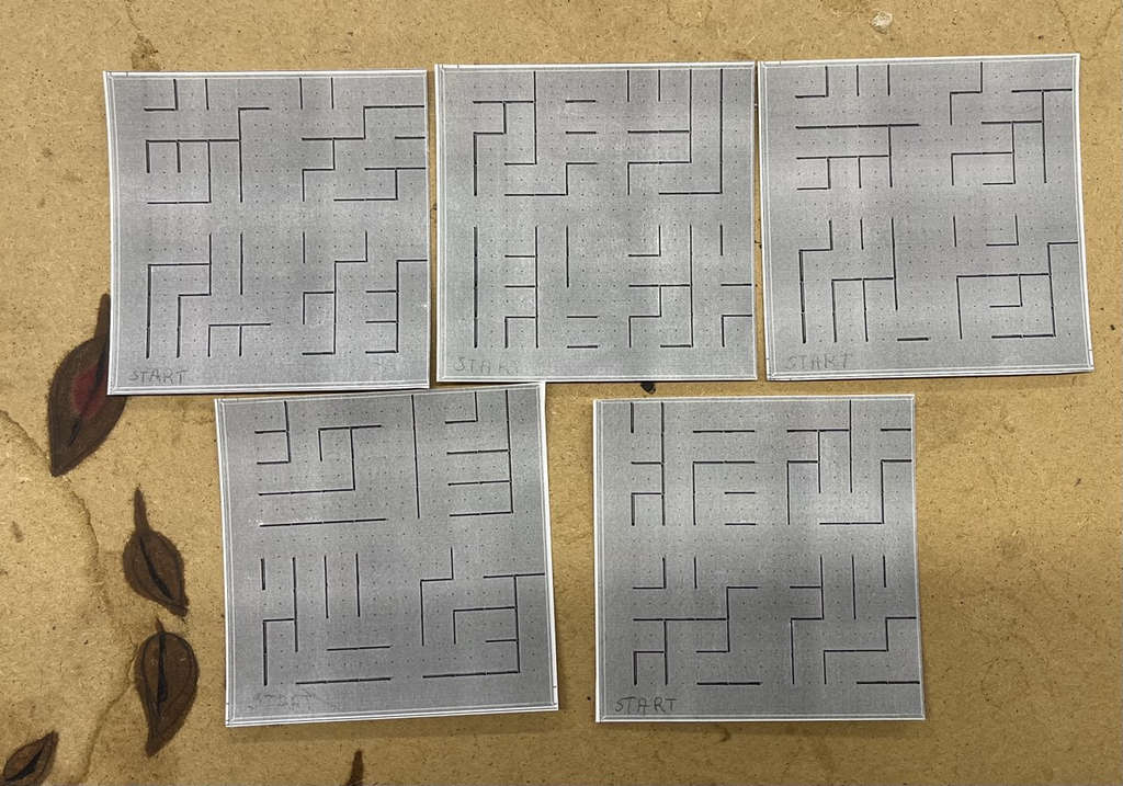
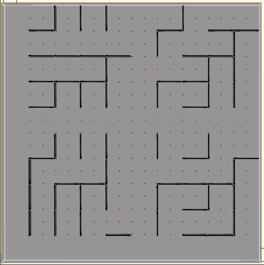
I developed an algorithm that generates a new maze every time it runs. The goal is to prevent the game from becoming repetitive or boring for the player. To allow customization, I created several maze map cards. The player can choose any card and arrange the maze according to that selected layout. Here are several examples of these cards.
While generating the maze, I considered several important details:
- First, I divided the game board into four quadrants. This allowed me to create a segmented maze so that the car could travel through all possible paths.
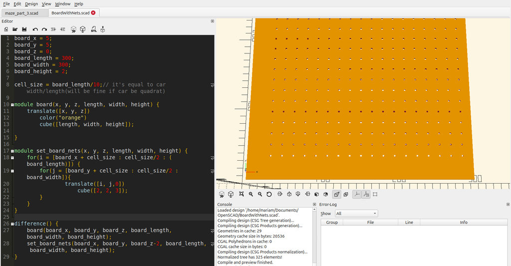
- I created a variable called
cell_size, which I plan to adjust later according to the dimensions of the car, ensuring that it can move smoothly through the maze paths. - I also performed calculations to add holes in the game board for mounting the maze walls. This allows the walls to be easily removed and rearranged into different configurations.
quadrants = [
	// Part 1
		[board_x+cell_size, board_y+cell_size],
	// Part 2
		[board_x+cell_size + board_length/2, board_y+cell_size],
	// Part 3
		[board_x+cell_size, board_y+cell_size + board_width/2],
	// Part 4
		[board_x+cell_size + board_length/2, board_y+cell_size + board_width/2]
];cell_size = board_length / 15;module set_board_nets(x, y, z, length, width, height) {
for(i = [board_x + cell_size : cell_size/2 : (board_length)]) {
for(j = [board_y + cell_size : cell_size/2 : board_width]){
translate([i, j, 2])
cube([2, 2, 3]);
}
}
}
difference() {
board(board_x, board_y, board_z, board_length+2, board_width+2, board_height);
set_board_nets(board_x+2, board_y, board_z-1, board_length+ 2, board_width+2, board_height);
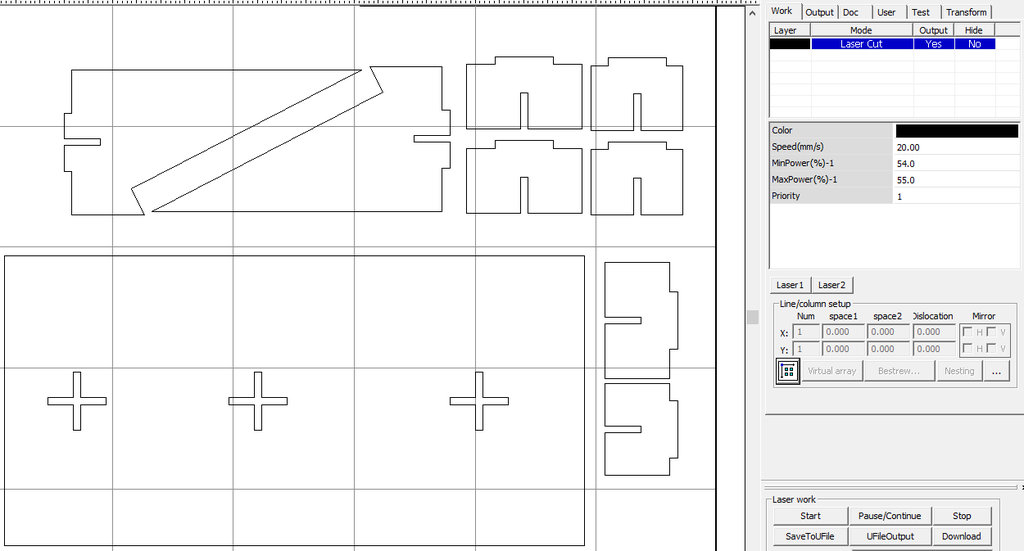
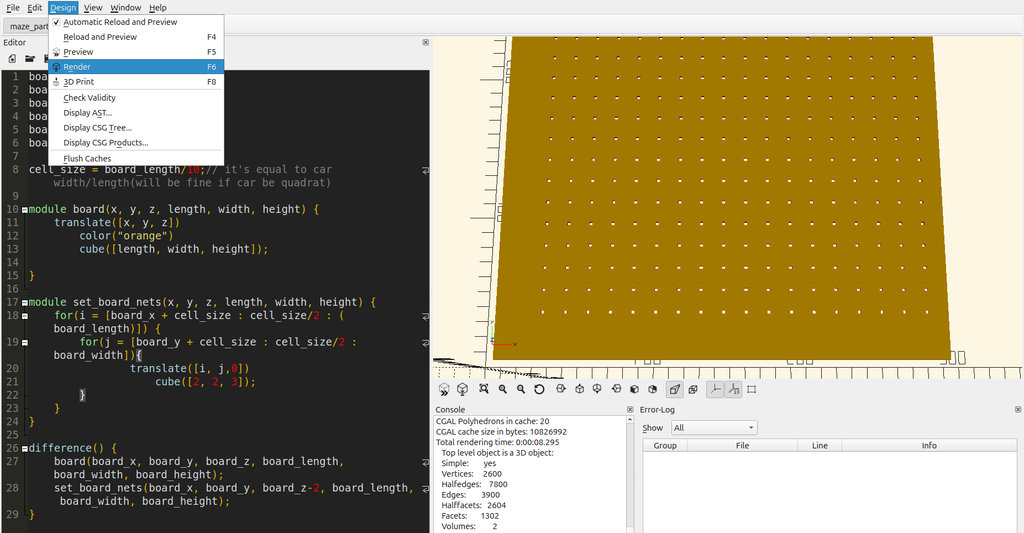
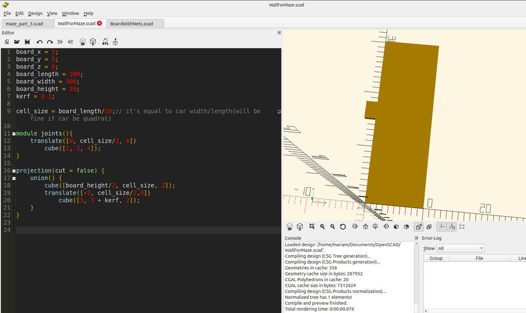
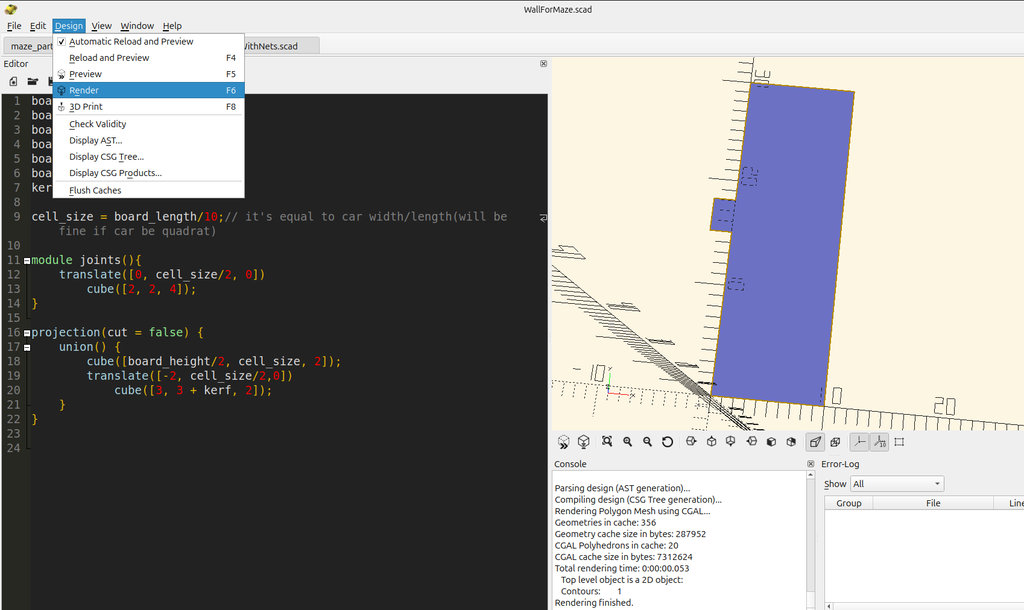
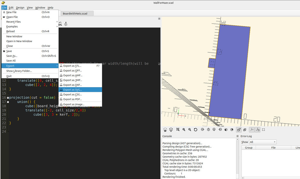
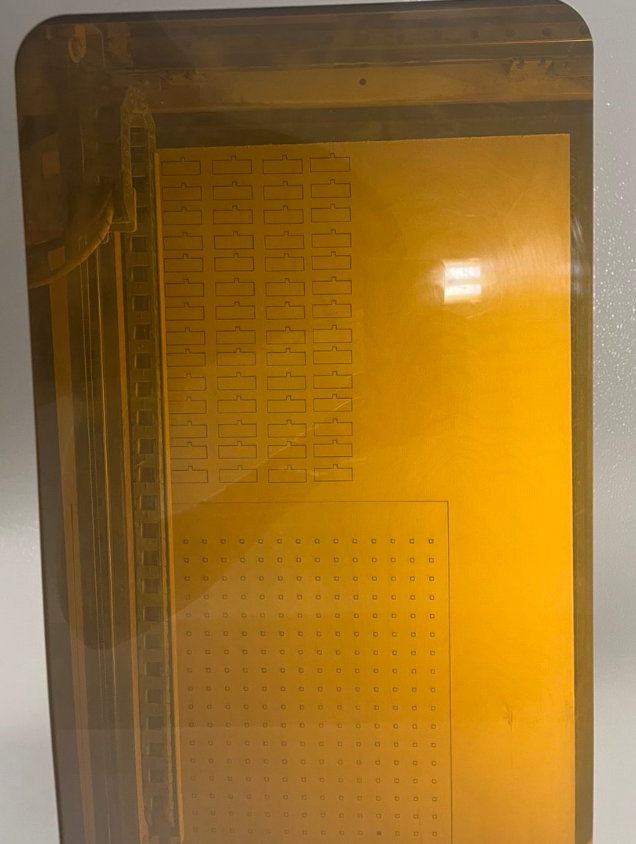
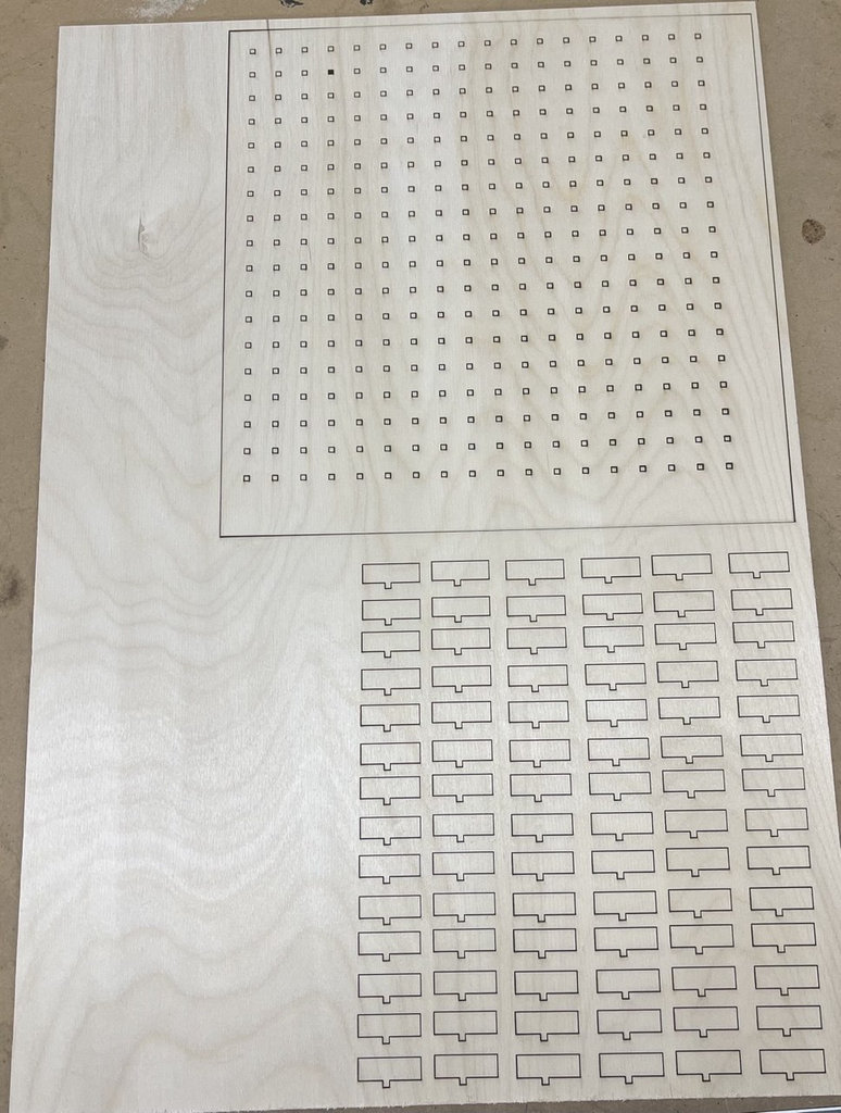
}At this stage, I used this algorithm both as an example of parametric design and as a foundation for my future work. Using the laser cutter, I manufactured a grid-based board and walls with joints. For this purpose, I created two additional OpenSCAD files. From my main algorithm, I separated the board with holes and prepared it specifically for laser cutting. I also created another file that contains the maze walls with joints.
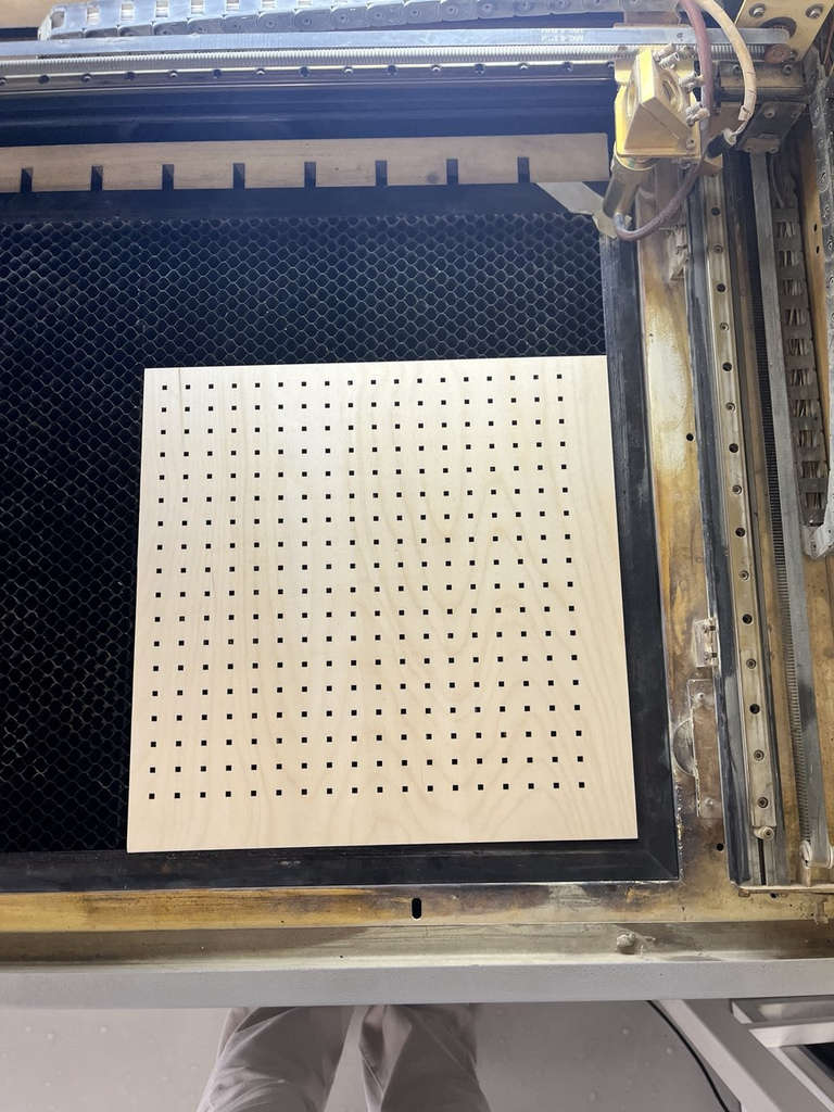
Here is the process.
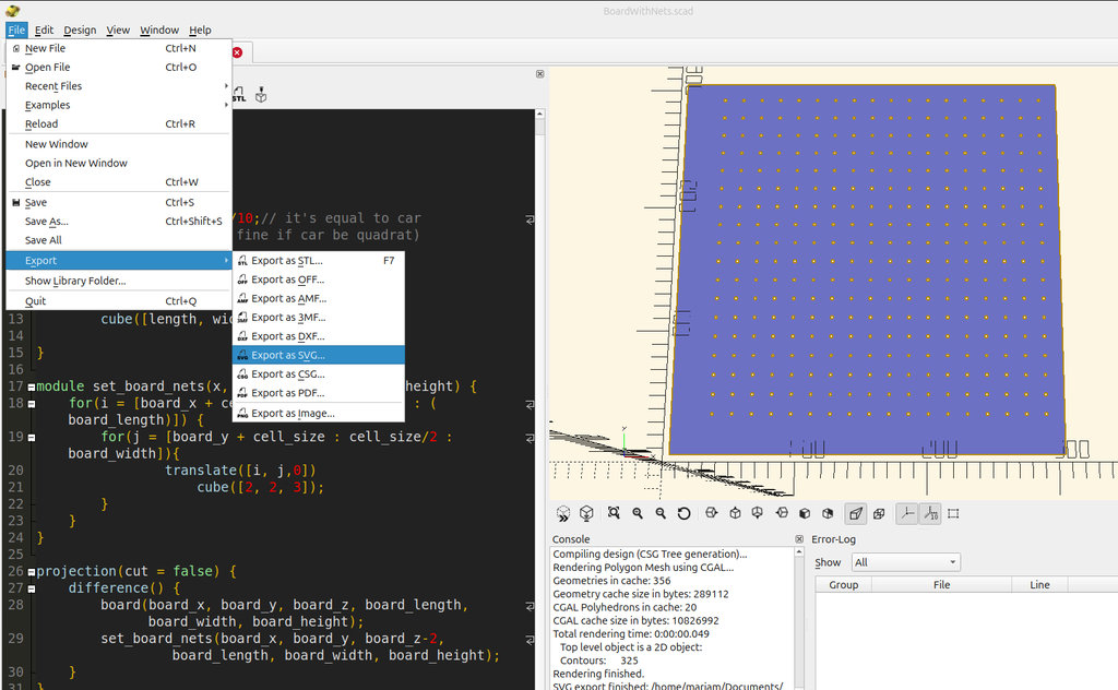
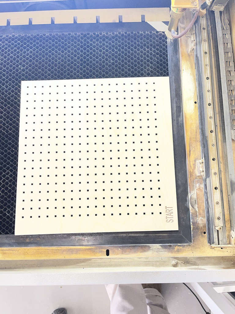
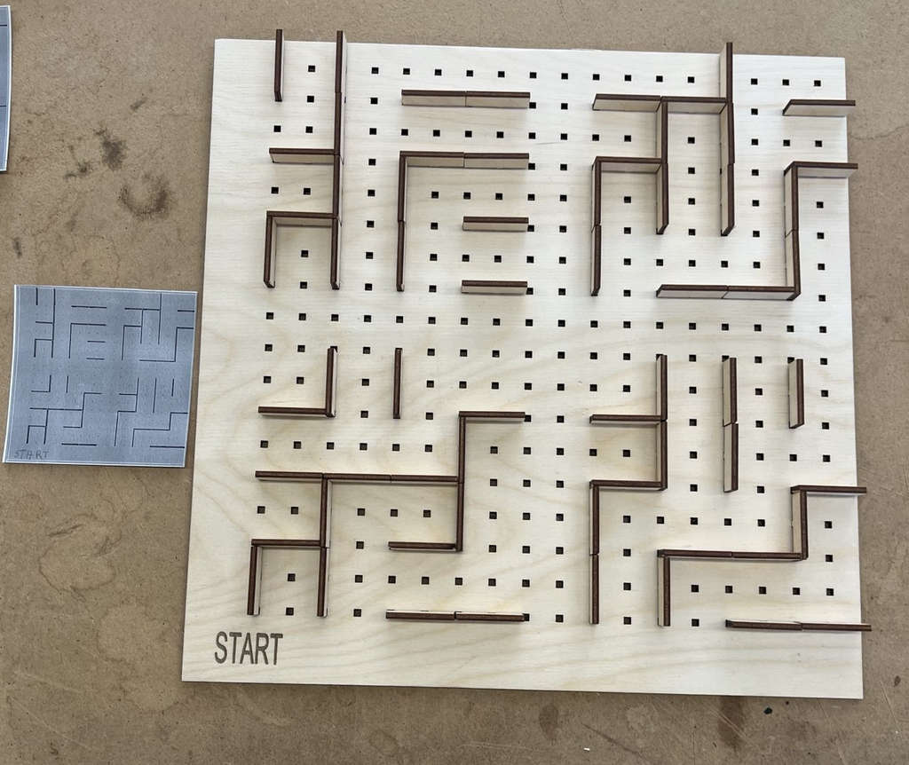
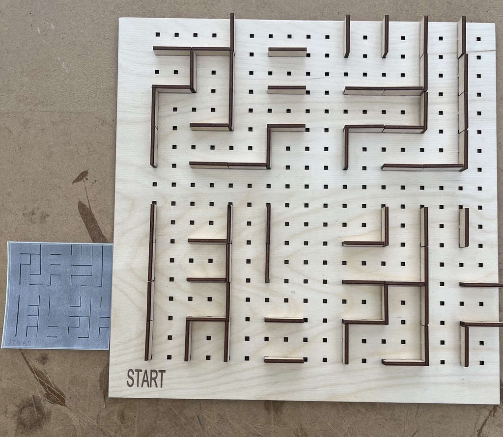
As a small prototype of my game environment, I manufactured a 300 × 300 mm board. After creating the SVG files, I proceeded with the laser cutting process.
Initially, for my 3 mm thick plywood, I set the machine parameters to speed 20, with minimum and maximum power set to 60 and 61. After waiting for the cutting process to finish, I noticed that the plywood was not fully cut. Additionally, the joints did not fit into the grid because I had not taken the kerf into account.
After that, I added the kerf value to the joint length and subtracted the kerf value from the grid slots on the board. For our machine, the kerf value is 0.2 mm, which we calculated during the group assignment.
The kerf characterization pattern was designed as a vector drawing and exported in SVG (Scalable Vector Graphics) format before importing it into RDWorks. SVG preserves vector paths accurately and is fully supported by our laser cutter workflow.

I also decided to add "START" to my game board. For this, I began testing to understand how to use the laser cutter in scan (engraving) mode instead of cutting mode. Here are the results.
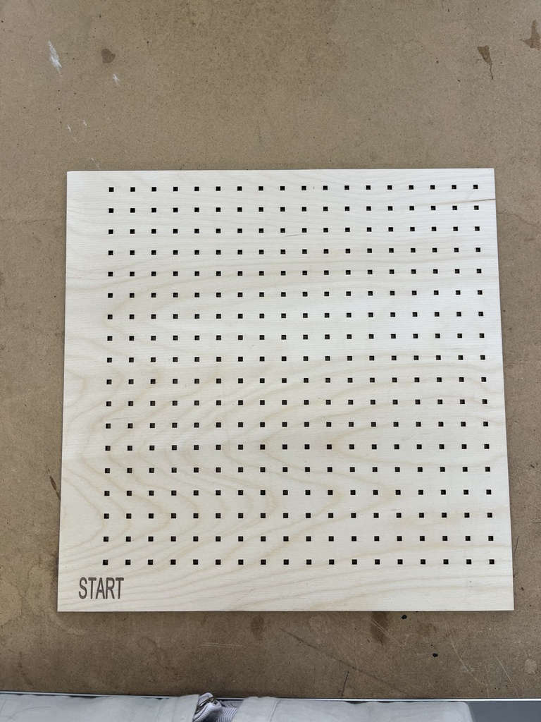
I selected two examples from the cards I created and assembled the corresponding maze layouts.
I think my final project is ready 😄 😄
This week helped me gain practical experience working with both the laser cutter and vinyl cutter. I learned how to prepare vector files, adjust machine parameters, and understand fabrication details such as kerf compensation and material testing. I also explored parametric design by developing a randomized maze algorithm and applying it to a physical prototype. Despite technical difficulties with file loss, I successfully completed several fabricated parts and improved my understanding of digital fabrication workflows. This week strengthened my confidence in combining design, programming, and manufacturing.
Vinyl Cutter Files
- Three leaves
- TootlesPath part black
- TootlesPath part gray
- TootlesPath part green
- TootlesPath part light black
- TootlesPath part pink
- TootlesPath part white
FreeCAD Files
OpenSCAD Files

AI prompt:
“And generate an image when finished this week.”