
Week 2
AI prompt:
“This image is a painting of me, and I would like you to create a new image with a computer-aided design theme showing this grandmother using CAD tools.”
Computer-Aided Design
This week, we had a wide range of materials to explore related to new tools and technologies. From these, I selected several tools that are closely aligned with the idea of my final project and focused on learning the specific features and details that could be useful for my design and development process.
The tools I used are:
During my university years, I had some limited exposure to computer-aided design (CAD), but it was quite a long time ago, and I no longer clearly remember the details. Because of that, I decided to approach these studies from the beginning and refresh my knowledge step by step.
FixThePhoto Online Editor
To avoid spending additional time and resources, I decided to use the online version of GIMP, especially since I do not require many tools. My workflow is limited to removing the background of selected images, adding text on top of the images, and apply a small amount of styling to the text.
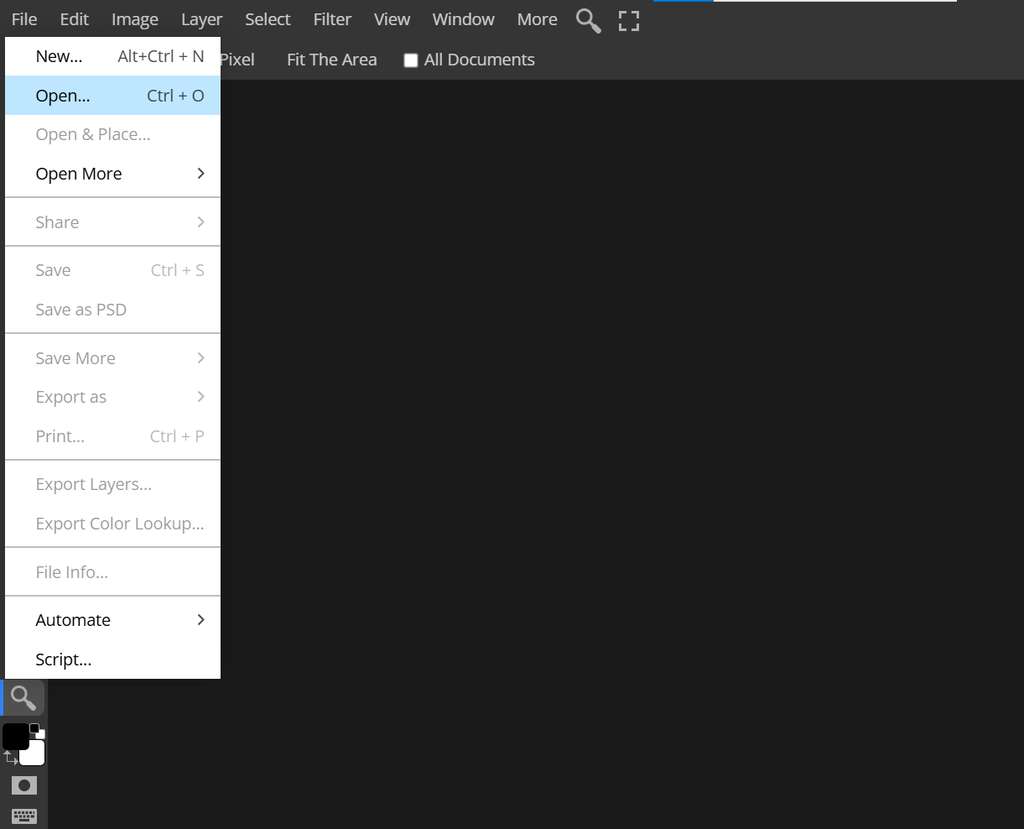
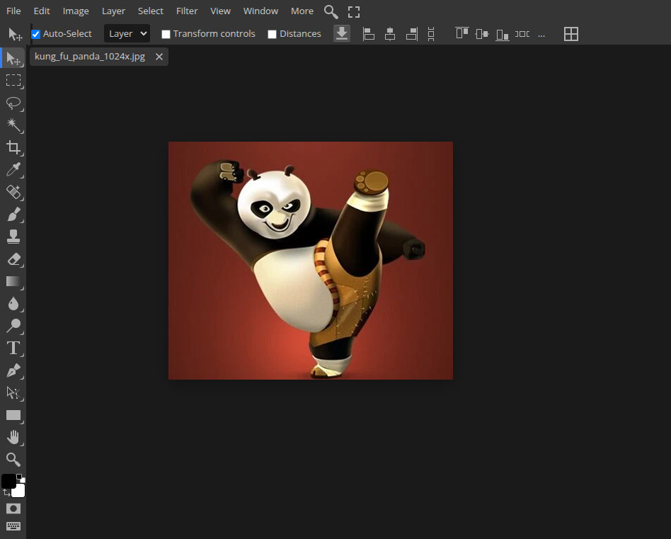
By opening this link, I can immediately access the GIMP interface, where I can upload the image I plan to work on.
In the following images, it is shown how I upload the image and view it within the GIMP working area.
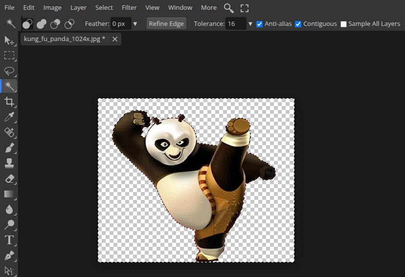
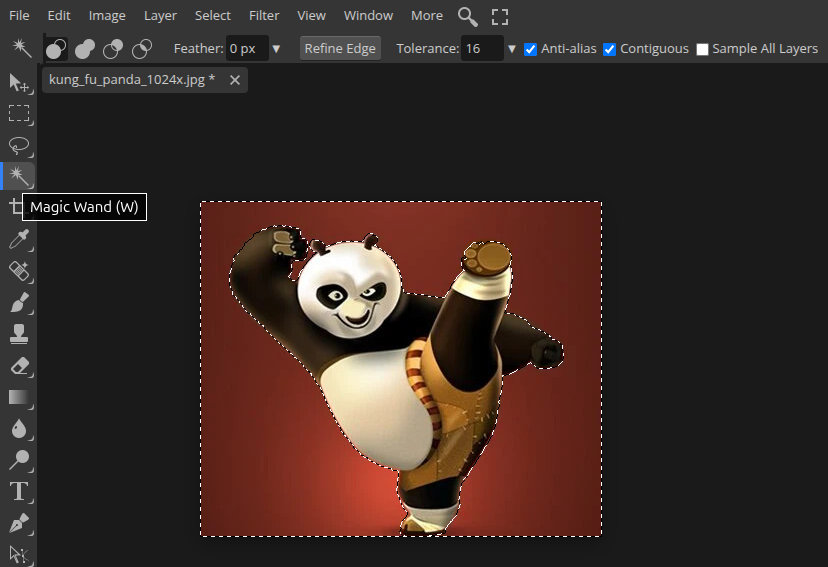
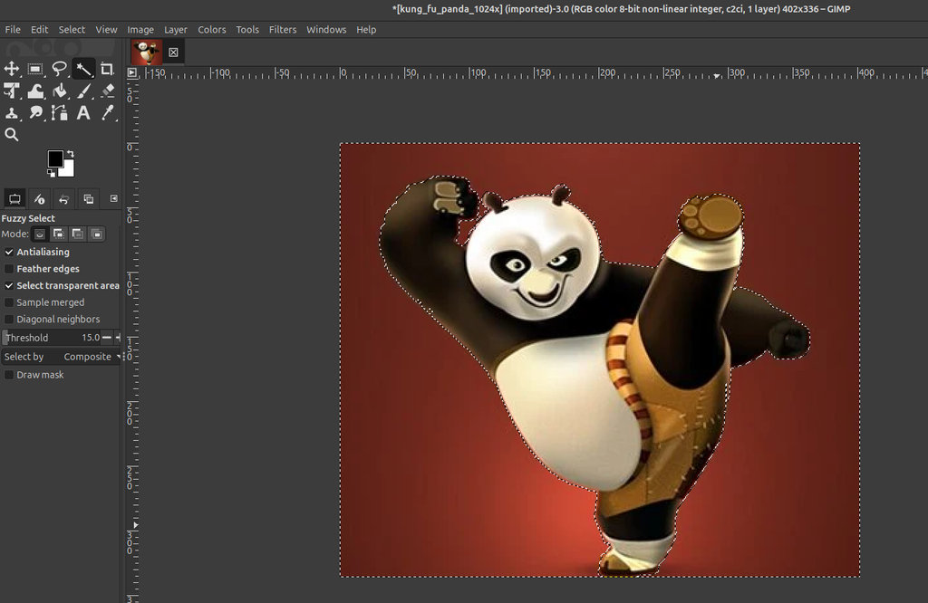
First, I need to remove the red background. Using the Magic Wand(W) tool, I select the entire background area and then press the Delete key to remove it. These steps can be seen in the images below.
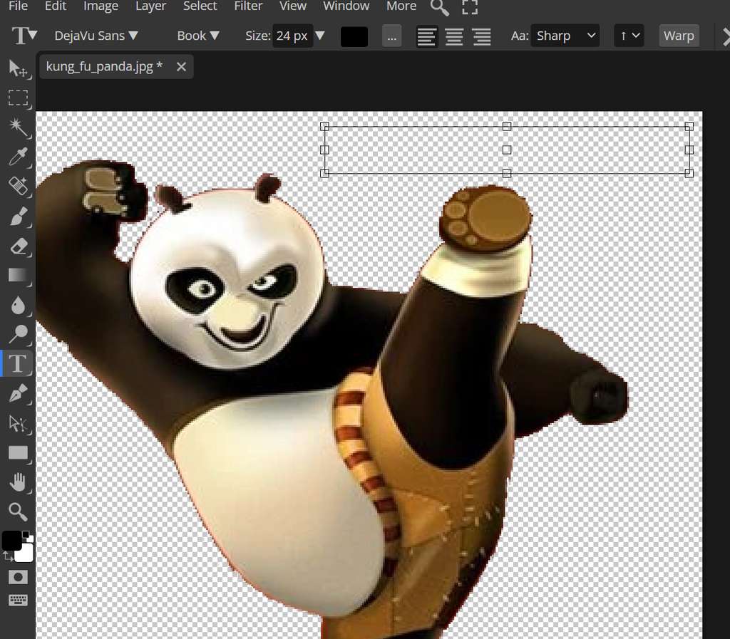
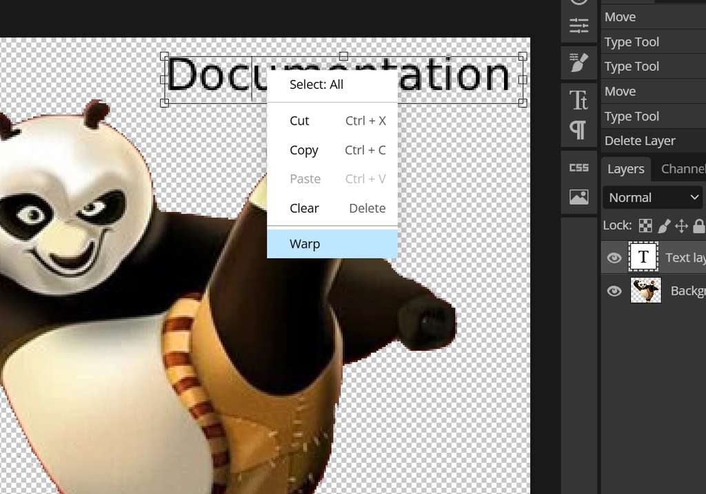
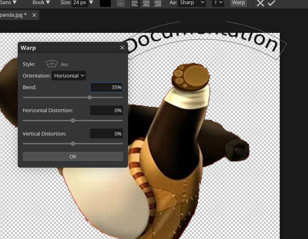
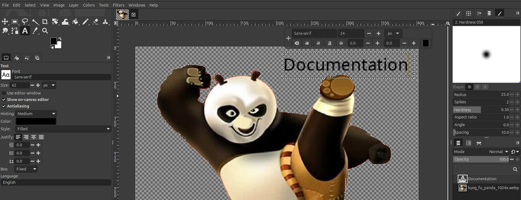
Next, I select the Type Tool(T) and click on the area where I want to place the text. After typing the text, I right-click on the text layer and choose Warp.
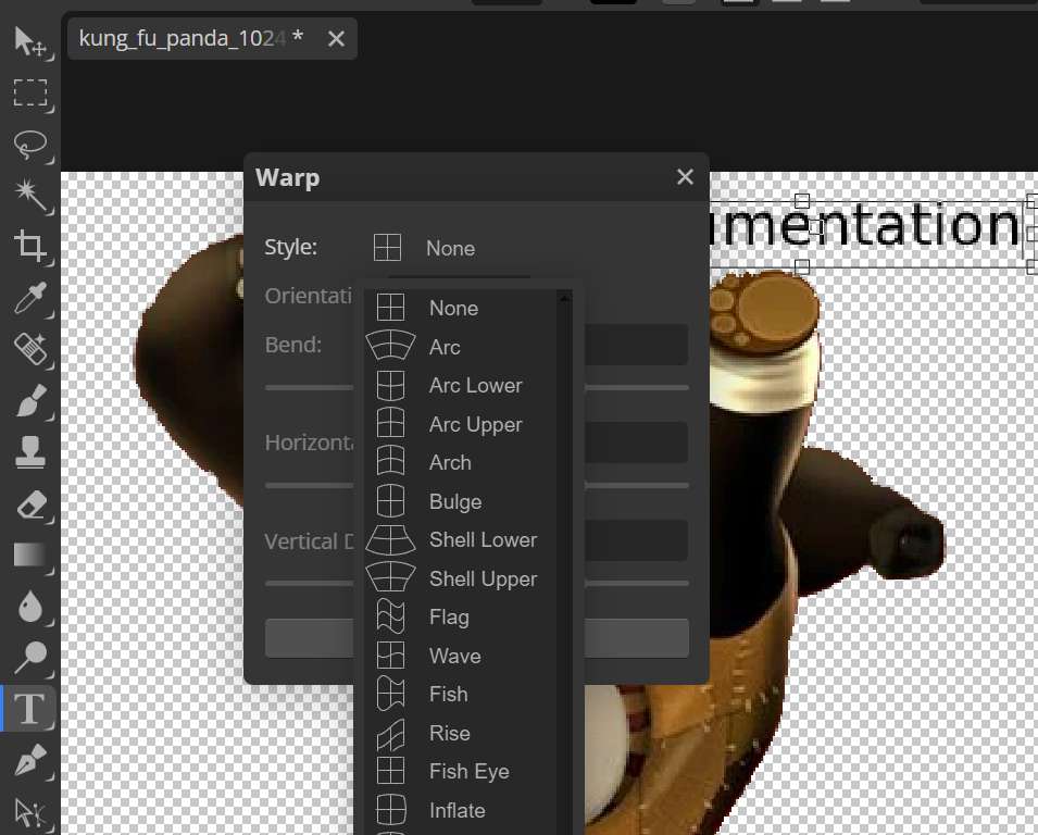
In the opened window, under the Style: section, I select the Arc option and then adjust the curvature using the Bend: parameter. In my case, I set the bend value to 35%.
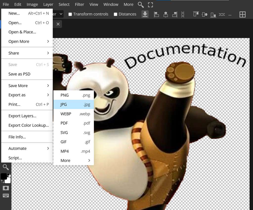
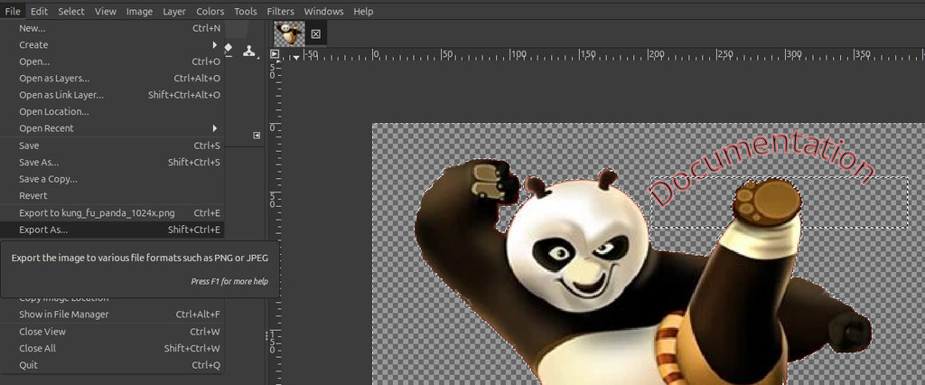
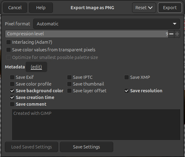
The image is now ready to be exported. To do this, I go to File → Export As and choose either .png or .jpg format. If the .png format is selected, the image transparency will be preserved. However, since my compress.py script converts all images to .jpg format regardless of the original file type, I saved the image directly as .jpg.
GIMP
Since the GIMP version I showed was the online version and quite different from the actual software, my global instructor Saheen suggested that I also document the original version.
I installed GIMP by typing the following command in the terminal:
sudo apt install gimpAfter that, GIMP was ready to use, and I repeated the same process in the original application.
First, I clicked File → Open and selected the image I wanted to modify.
Once the image was opened in GIMP, I selected the Fuzzy Select Tool (or simply pressed U on the keyboard). Then, while keeping the main object selected, I selected the background so I could make it transparent.
Next, I selected the Text Tool, clicked where I wanted the text to appear, and typed my text.
Here is a short video showing how I curved the text.
I selected the Path Tool, clicked at the beginning of the text, then clicked at the end of the text. By dragging the middle section of the path, I shaped it into the curve I wanted the text to follow.
Then, from the lower section, I selected Create New Layer, gave it a name, and created a new layer.
After that, I selected the text again, right-clicked on it, and chose Text Along Path. The text was now curved, but it still had no fill. To fix this, I went to: Windows → Dockable Dialogs → Paths
Then I selected the curved text path, right-clicked on it, and chose Fill Path...
At this point, the text was complete. I hid the previous text layer and was ready to export the file.
To do that, I selected: File → Export As
Then I chose the location where I wanted to save the file. A new window appeared, I clicked Export again, and the file was ready.
Here is the exported .png file.

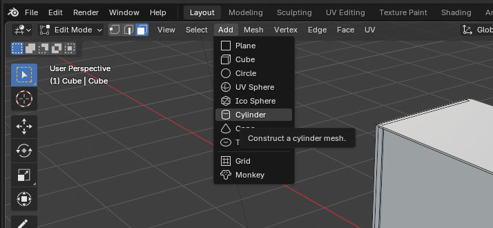
OpenSCAD
It would have been logical to continue describing my work with Inkscape, however, at this stage I decided to explain how I worked with OpenSCAD. Since Inkscape is not a parametric design tool and I want to design parts related to my final project, I chose to start modeling the parts in OpenSCAD. After that, I convert the model into a 2D format using Inkscape. This workflow allows me to prepare the design for laser cutting.
OpenSCAD is an open-source, script-based 3D CAD modeler often referred to as a "3D compiler". Unlike traditional interactive software, we create models by writing code that describes the object's geometry.
Since I want to create a maze for my game, where my robot overcomes obstacles and collects coins, I decided to design a game board in the form of a labyrinth.
First, I downloaded the OpenSCAD software using the official link. After completing the installation, I created a new file where I could start writing code to generate the board.
To design the labyrinth, I used the OpenSCAD Cheat Sheet as a reference guide. Here is a quick reference guide to the most essential commands and syntax for parametric 3D modeling.
I would also like to mention a few resources that helped me learn OpenSCAD during Fab Academy. These tutorials and references were very useful while I was learning the basics of parametric design and creating my own models.
Some of the resources I used are listed below:
- OpenSCAD Official Documentation
- OpenSCAD User Manual
- OpenSCAD Official Cheat Sheet
- MakerTutor OpenSCAD Tutorials
- Teaching Tech – OpenSCAD Introduction
- Paul McWhorter OpenSCAD Tutorial Series
I used the concept of functions (modules) in OpenSCAD, along with several core features such as difference, translate, and color. I also worked with basic 3D primitives like cube, as well as transformations and Boolean operations.
Here is the first module, which I use to define the area where the robot will be controlled using a joystick.
module labyrint(x, y, z, length, width, height) {
   difference() {
        translate([x, y, z])
            color("#472d02ad")
            cube([length, width, height]);

        translate([x+1, y+1, z+1])
            color("#f7b03ead")
            cube([length-2, width-2, height]);
   };
}
Below is the code used to draw the walls and give the board a labyrinth structure.
module wall(x, y, z, length, width, height) {
translate([x, y, z])
color("red")
cube([length, width, height]);
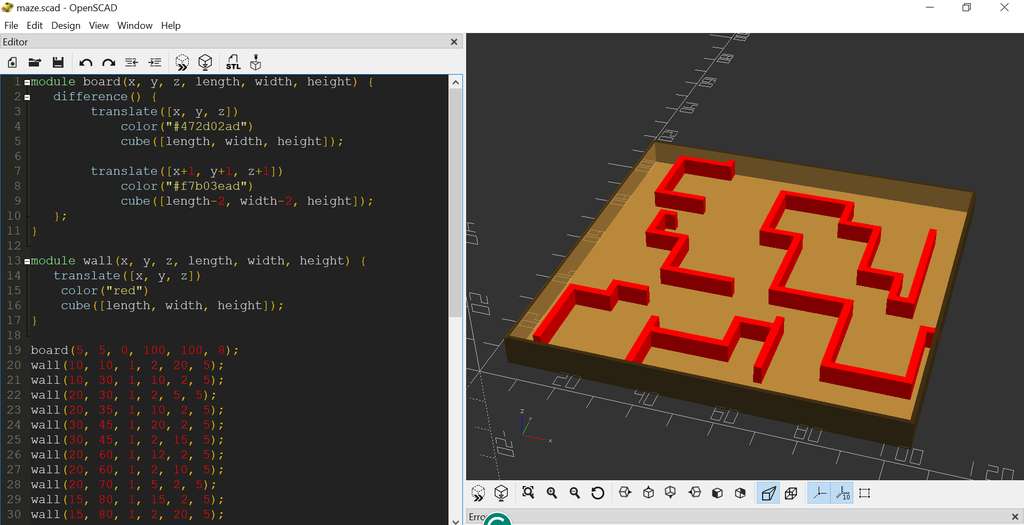
}By calling the modules at the bottom of the file, the entire labyrinth is generated inside the board.
labyrint(5, 5, 0, 100, 100, 8);
wall(10, 10, 1, 2, 20, 5);
wall(....)..
By passing different parameters to the modules, it is possible to create labyrinths of various sizes and layouts.
This second module can be called multiple times, depending on how many walls are needed inside the board.
To avoid calling the wall() method many times, I grouped the parameters passed to the walls into a single array. Although this approach works, it is not ideal. In the future, I plan to implement an algorithm to generate the labyrinth automatically, instead of manually entering a large amount of data.
wall_data = [
[10, 10, 1, 2, 20, 5], [10, 30, 1, 10, 2, 5], [20, 30, 1, 2, 5, 5],
[20, 35, 1, 10, 2, 5], [30, 45, 1, 20, 2, 5], [30, 45, 1, 2, 15, 5],
[20, 60, 1, 12, 2, 5], [20, 60, 1, 2, 10, 5], [20, 70, 1, 5, 2, 5],
[15, 80, 1, 15, 2, 5], [15, 80, 1, 2, 20, 5], [15, 100, 1, 15, 2, 5],
[30, 100, 1, 2, 5, 5], [50, 90, 1, 20, 2, 5], [70, 82, 1, 2, 10, 5],
[70, 80, 1, 10, 2, 5], [80, 60, 1, 2, 22, 5], [80, 60, 1, 10, 2, 5],
[90, 50, 1, 2, 12, 5], [90, 50, 1, 5, 2, 5], [95, 50, 1, 2, 35, 5],
[50, 70, 1, 2, 20, 5], [50, 70, 1, 12, 2, 5], [60, 45, 1, 2, 25, 5],
[60, 45, 1, 20, 2, 5], [80, 20, 1, 2, 27, 5], [80, 20, 1, 20, 2, 5],
[100, 20, 1, 2, 20, 5], [100, 40, 1, 5, 2, 5], [35, 6, 1, 2, 20, 5],
[35, 20, 1, 20, 2, 5], [55, 20, 1, 2, 10, 5], [55, 30, 1, 10, 2, 5],
[65, 15, 1, 2, 20, 5]
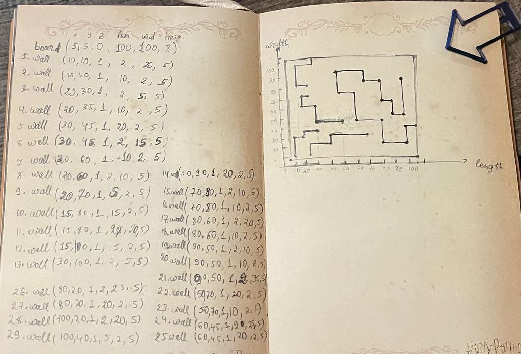
];Here is the sketch I used to calculate the positions and orientations of the walls and to design the labyrinth.
Here is the final result generated in OpenSCAD.
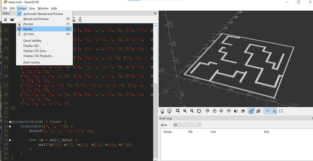
At this stage, it was necessary to save the file in SVG format in order to open and process it in Inkscape. To do this, I attempted to use Render and then Export as SVG.
However, during rendering, I encountered an error message.
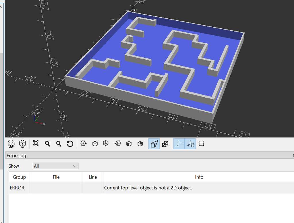
After a brief search, I realized that OpenSCAD requires the 3D model to be explicitly flattened into a 2D plane before it can generate a vector file such as SVG.
To solve this issue, I used the projection(cut = true) module, which takes a 3D object and projects it onto the X-Y plane.
I also added a translate([0, 0, -2]) transformation inside the projection. Since the walls of my model start at Z = 1, a cut at Z = 0 might not intersect them correctly. By shifting the model downward, I ensured that the OpenSCAD projection “cutting plane” properly intersects the walls and produces a correct 2D projection.
Below is the full module call wrapped inside the projection() function:
projection(cut = true) {
    translate([0, 0, -2]) {
        board(5, 5, 0, 100, 100, 8);

        for (w = wall_data) {
            wall(w[0], w[1], w[2], w[3], w[4], w[5]);
        }
    }
}
Here are the steps to render the model and export it as an SVG file.
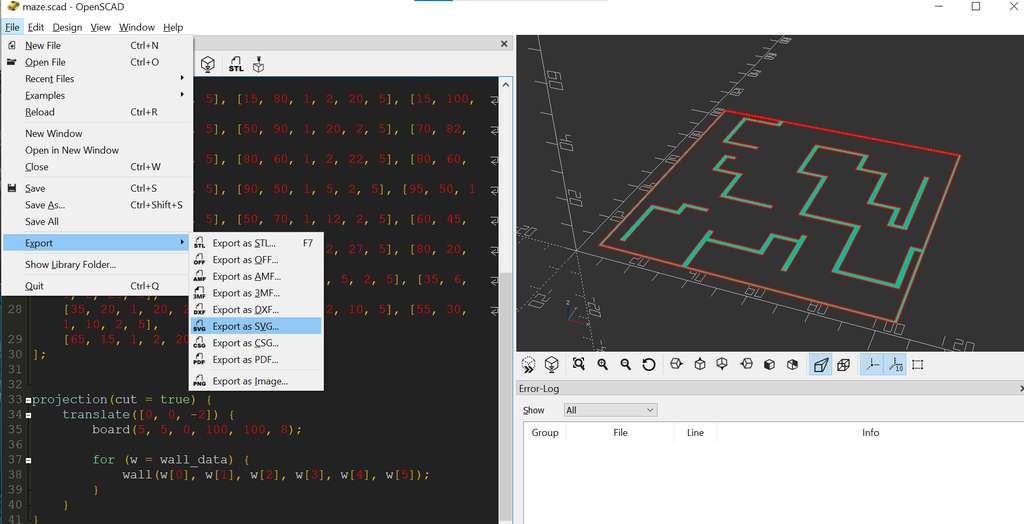
Inkscape
Next, I performed a few basic operations in Inkscape. First, I downloaded Inkscape from the official website. After completing the installation, the software was ready to use. Inkscape is a powerful, professional-grade, free and open-source vector graphics editor.
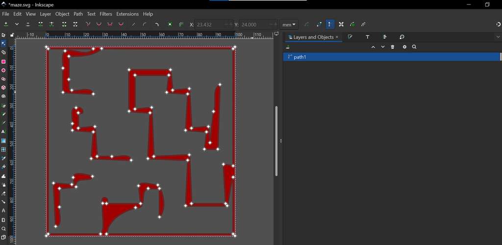
Since I already had the 2D .svg file of the game labyrinth board, I opened it in Inkscape by navigating to File → Open → select file.svg.
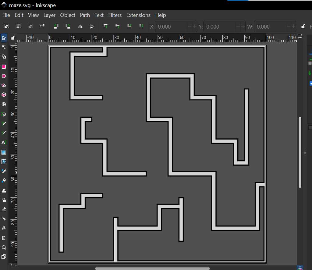
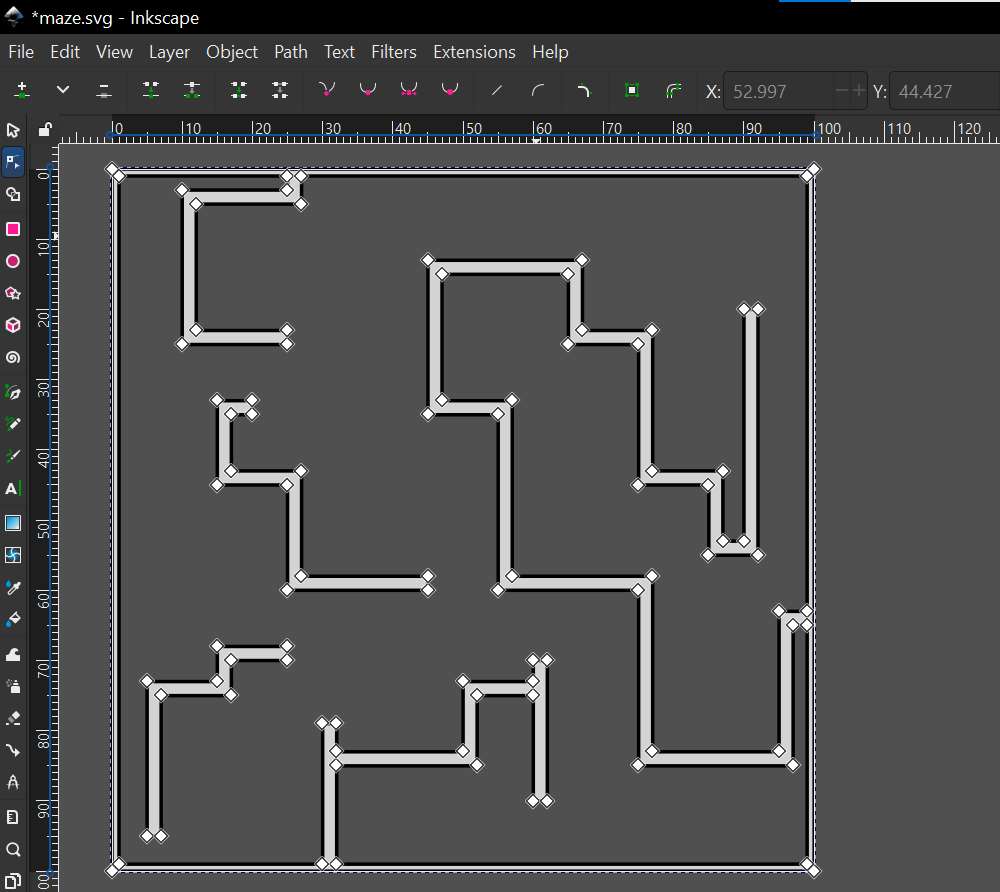
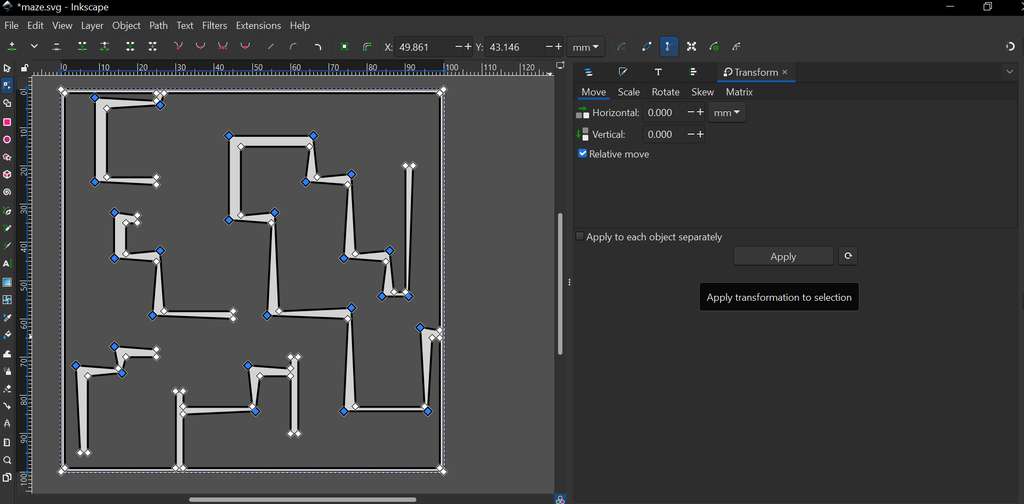
In Inkscape, I performed the following operations:
-
Scale
By selecting the object, handles appear on the corners and edges. These can be dragged to resize the object and adjust the thickness of the elements. I selected corner nodes and scaled them slightly to achieve a more visually distinct layout.
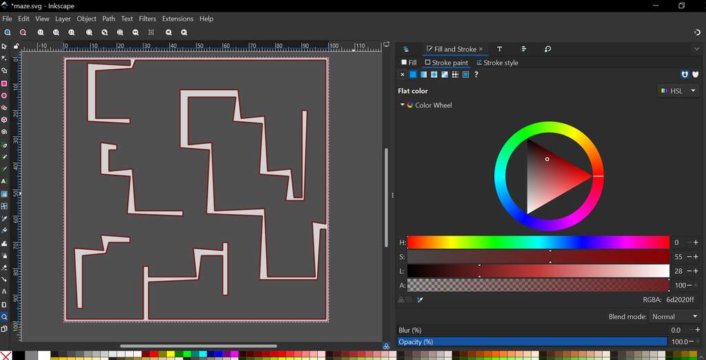
-
Stroke
To access the Stroke settings, I used
Ctrl + Shift + F. In the Fill tab, it is possible to change the color of the filled areas inside the shapes. The Stroke Paint option allows changing the stroke color, while Stroke Style is used to adjust the stroke width and appearance. The applied changes can be seen in the following screenshots.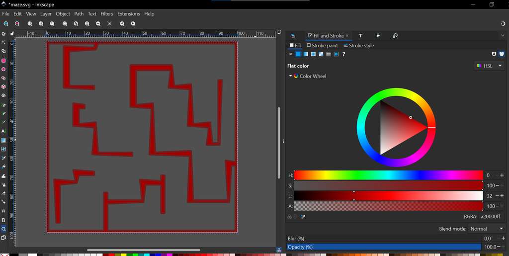
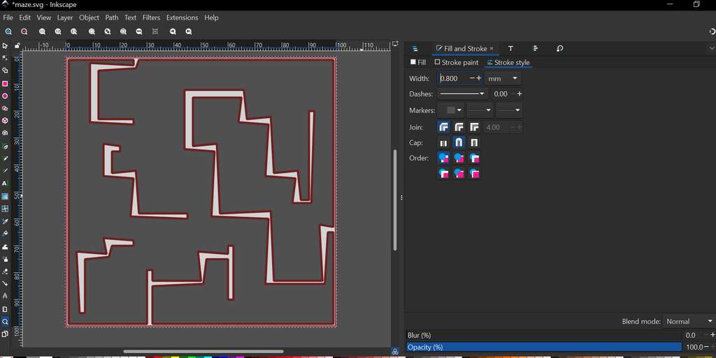
-
Cleanup (Refining Paths)
By pressing
Ctrl + L, Inkscape automatically reduces the number of nodes, making the file smaller and smoothing the curves.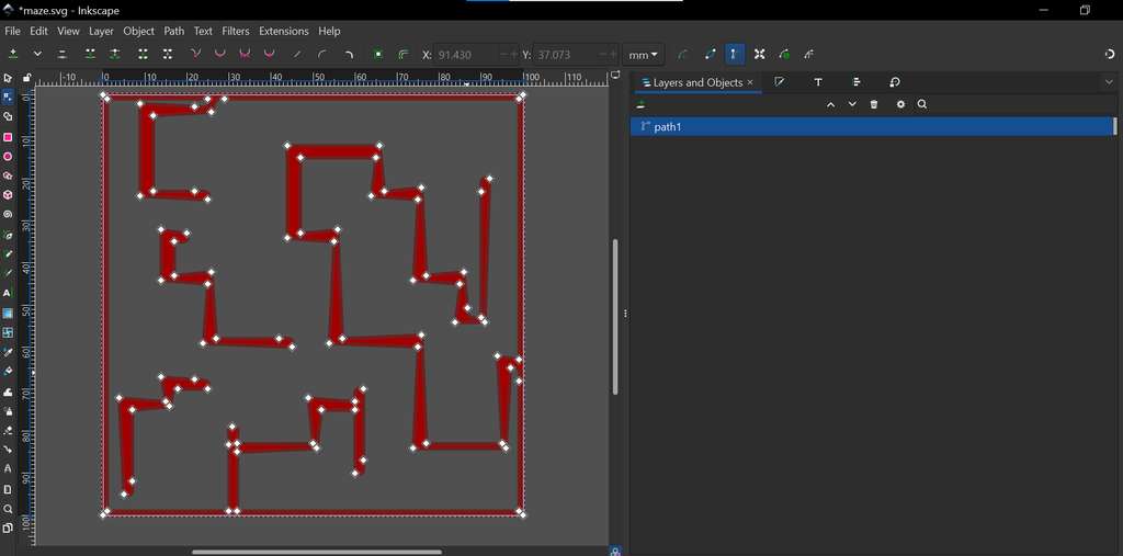
FreeCAD
Now, I will move on to exploring FreeCAD and present the work I have done.
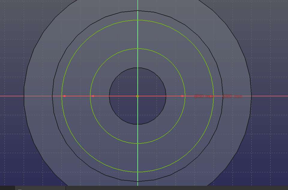
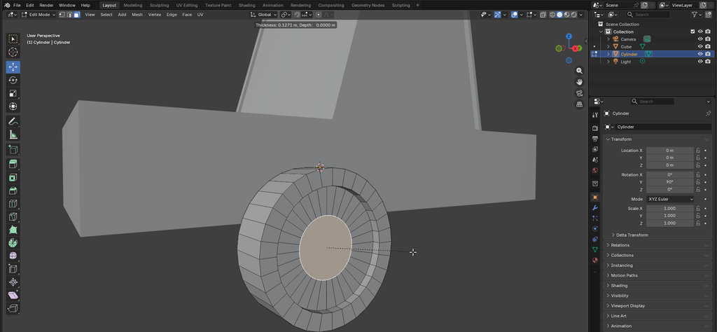
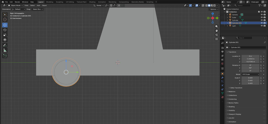
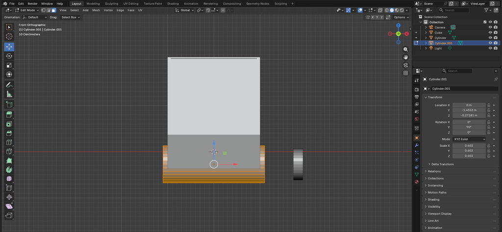
FreeCAD is a free, open-source, parametric 3D computer-aided design (CAD) software that allows ideas to be designed and, at least conceptually, realized. Using FreeCAD, I created a model of my robot’s wheel, which I plan to further improve later by making it fully parametric.
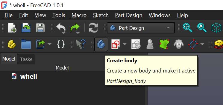
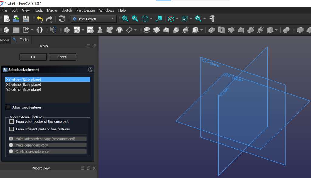
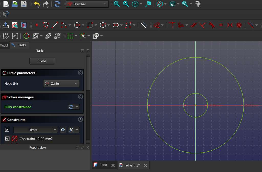
After downloading and installing FreeCAD, I created a new empty file. Inside it, I created a Body and a Sketch.
A Body is a container that holds all sketches and 3D features related to a single solid object. A Sketch can be added when the Body is active and is used to define the shape of the object. After creating the Sketch, I selected the plane on which I wanted to draw the 2D projection of my object.
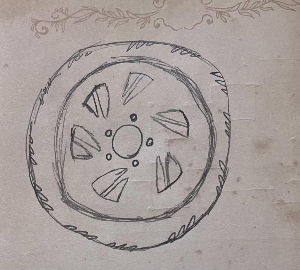
Below is my initial concept sketch of the wheel, which I then implemented in the software. I am not sure whether a similar wheel design already exists, whether it could support weight, or whether it would perform optimally in rotation. However, this represents my current idea and is subject to change and improvement.
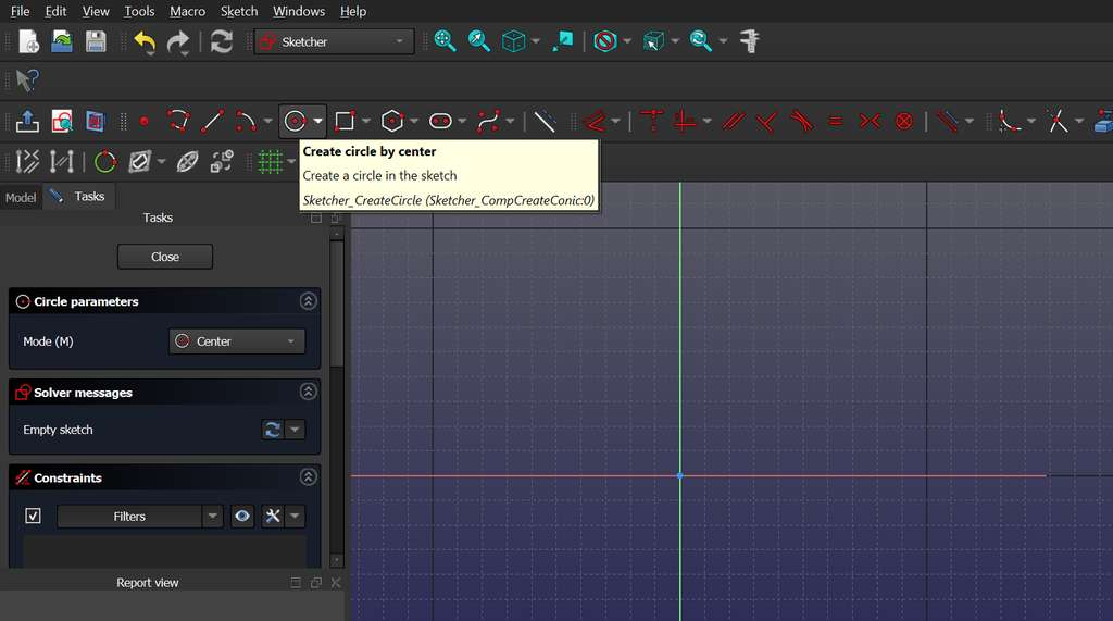
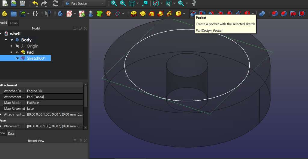
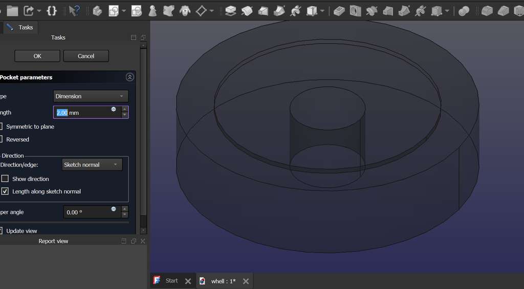
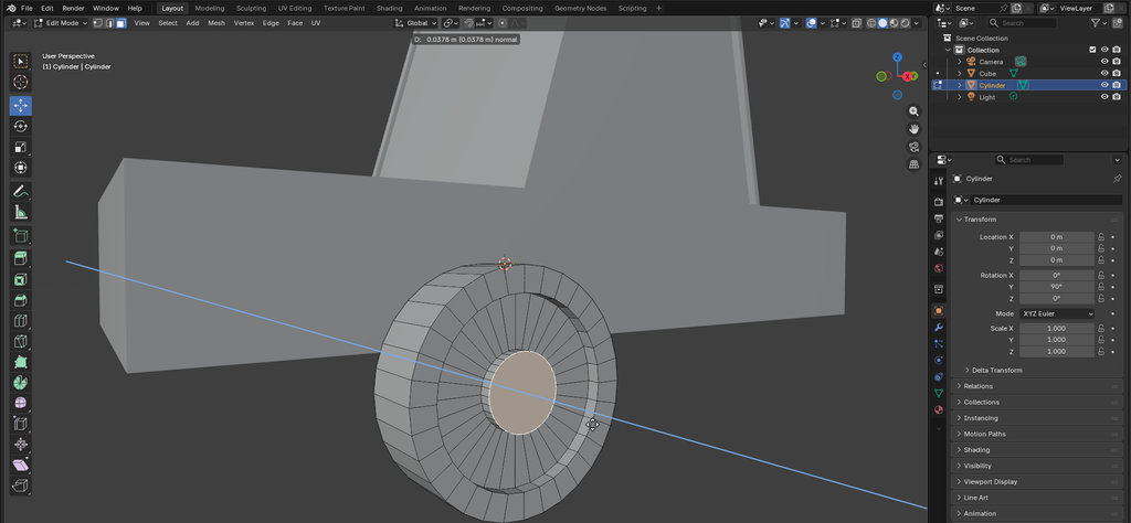
After defining the main circles, I used the Pocket tool to subtract the smaller circle from the larger one, forming the basic structure of the wheel.
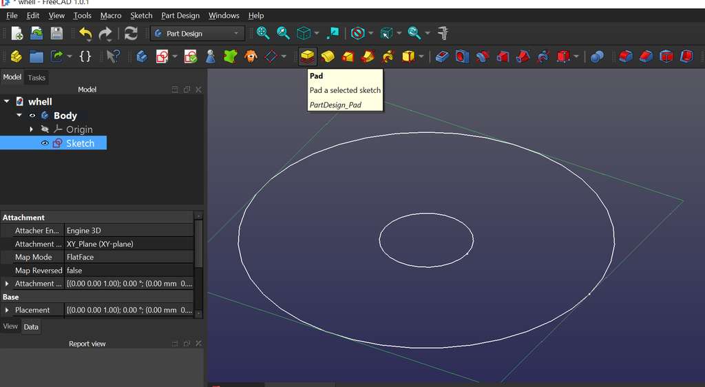
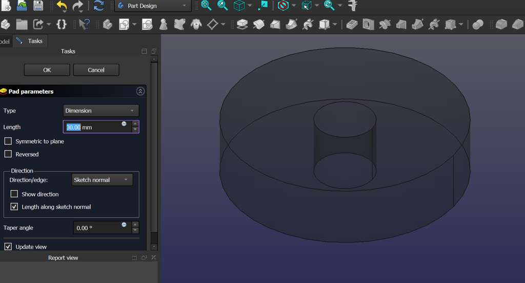
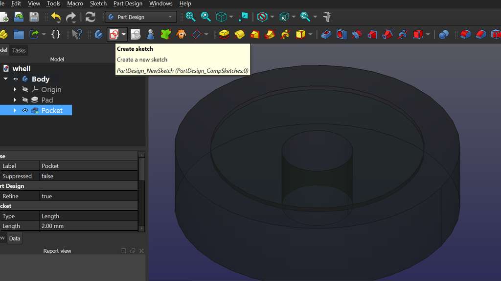
Next, I selected the Pad feature and created a new Sketch on top of it to add additional geometry. I drew another circle and applied a small extrusion depth—not a full one—mainly for visual enhancement.
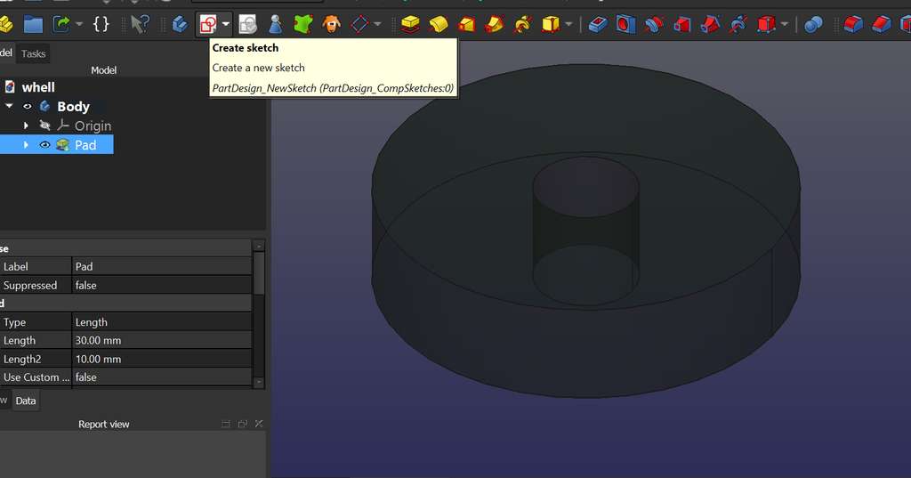
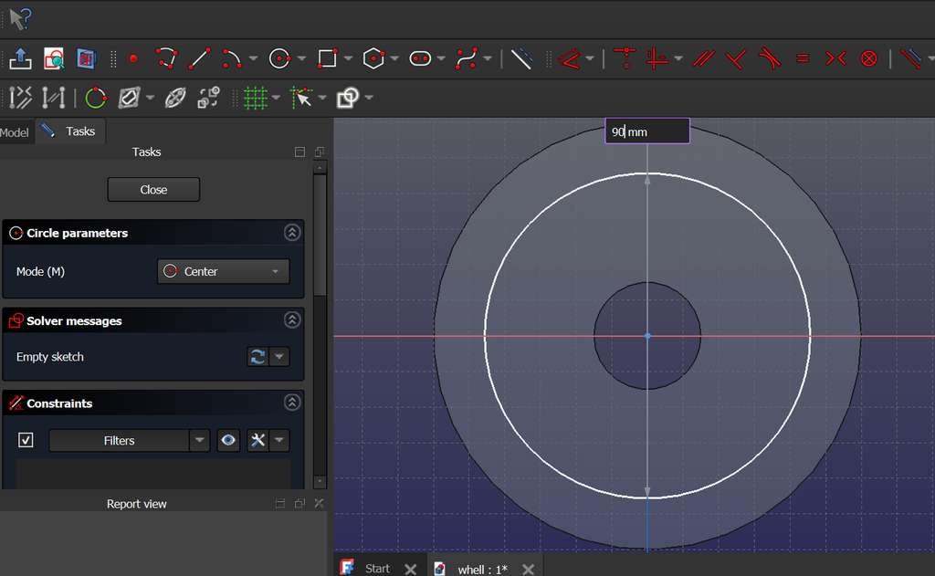
Then, I selected a new plane and created another Sketch for further constructions.
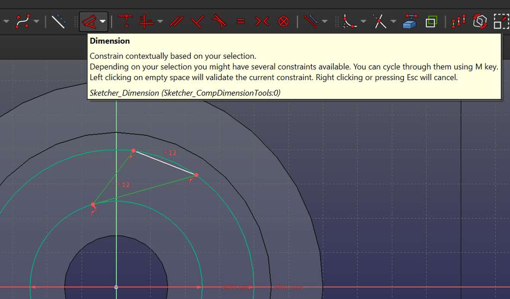
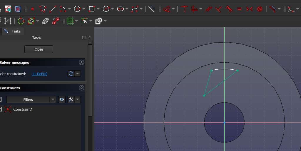
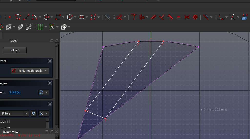
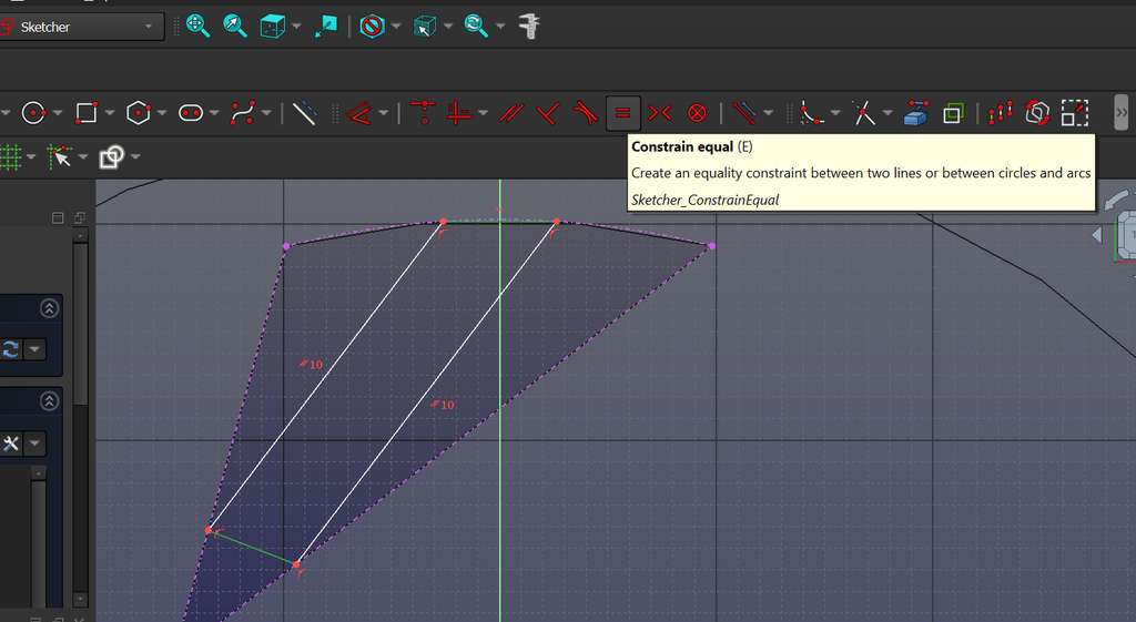
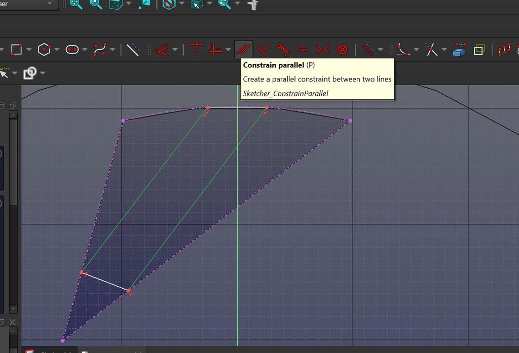
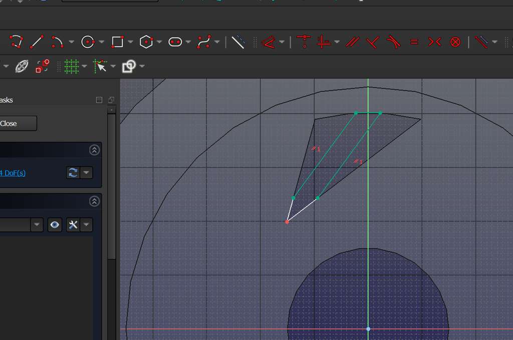
I created two additional circles, inside which I planned to design the main internal patterns of the wheel. Using the Create Line tool, I drew a triangle.
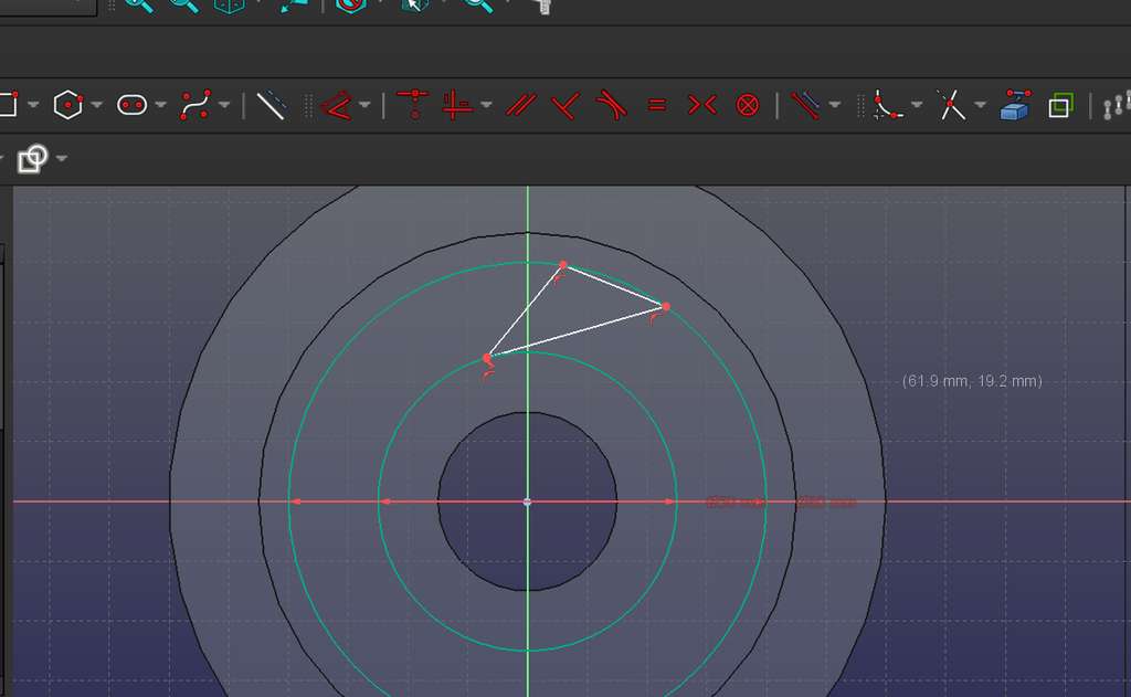
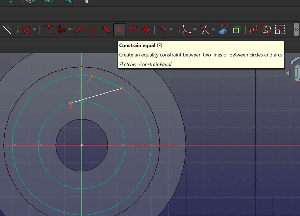
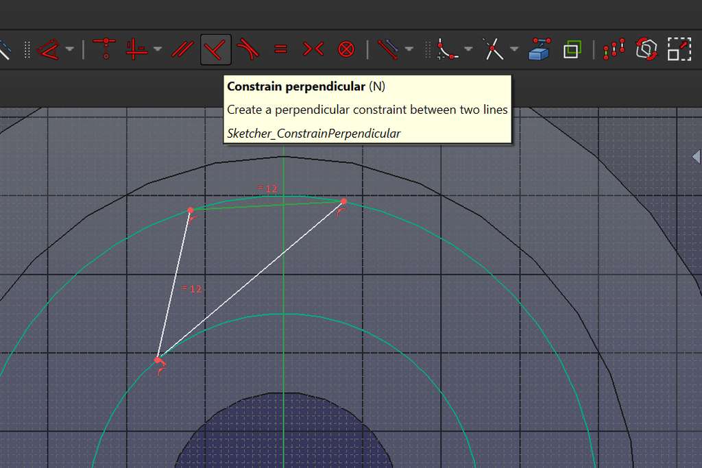
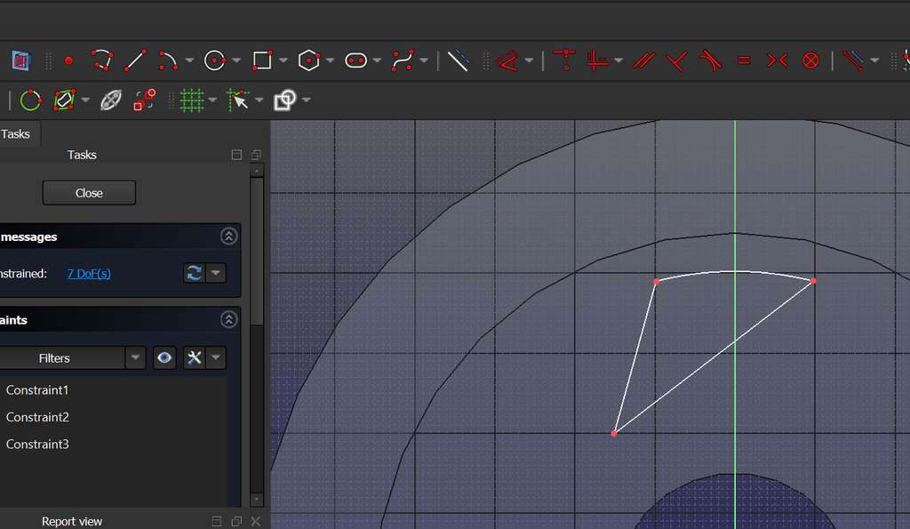
By applying constraints, I ensured that the triangle remained consistently positioned between the two circles, which is indicated by the sketch turning green.
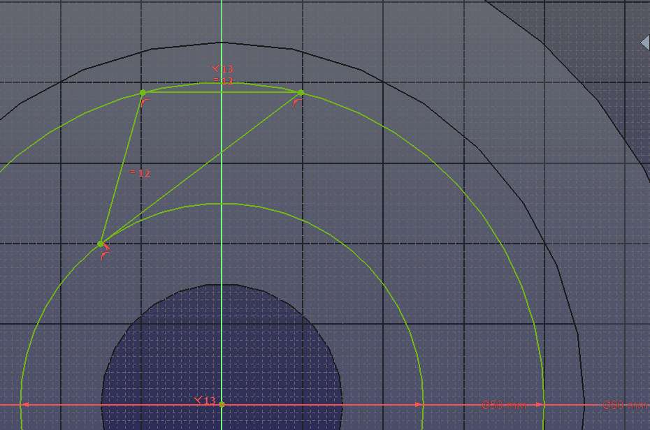
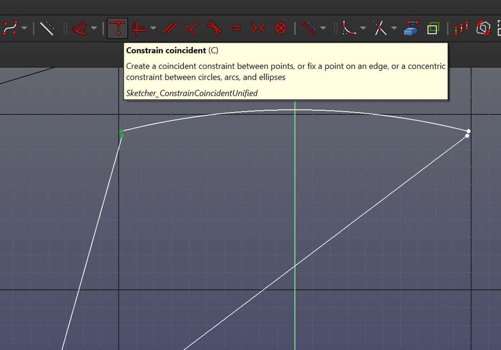
After the triangle turned green (fully constrained), I used the Create Arc by Center tool to draw an arc along the edge of the triangle. Then, I removed the unnecessary remaining segments.
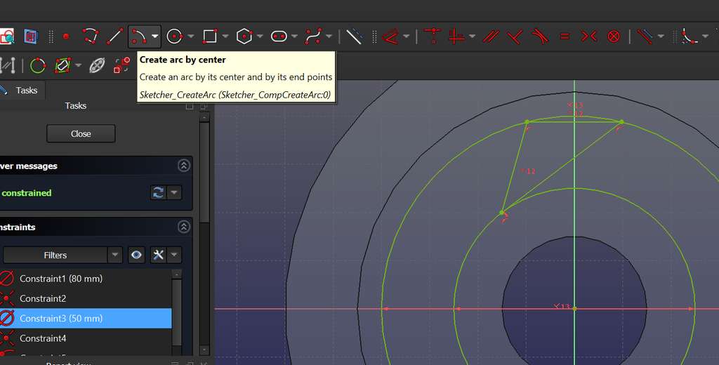
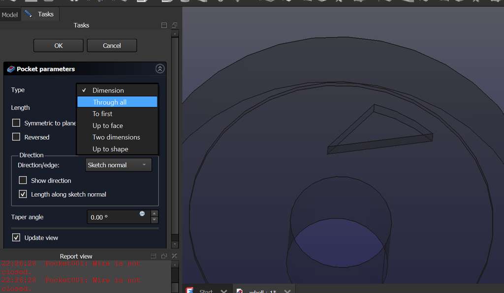
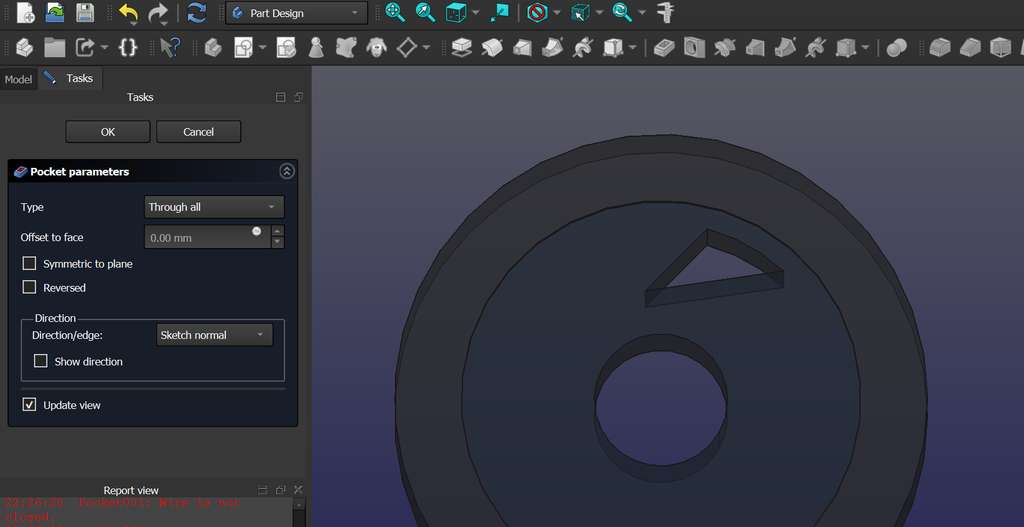
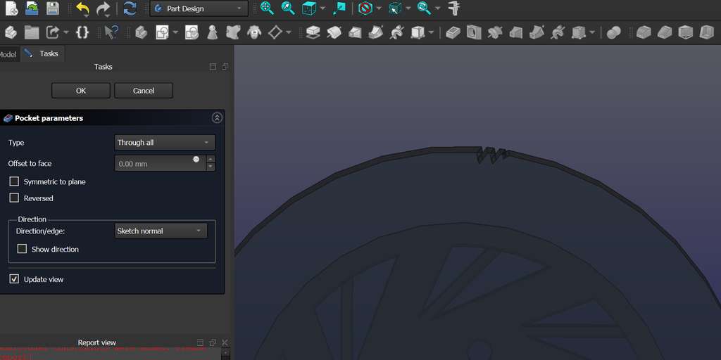
After closing the sketch, when I tried to create a Pocket, I encountered an issue.

By returning to the Sketch, I noticed that some edge points were disconnected. I fixed this by reconnecting them using the Constrain Coincident constraint.
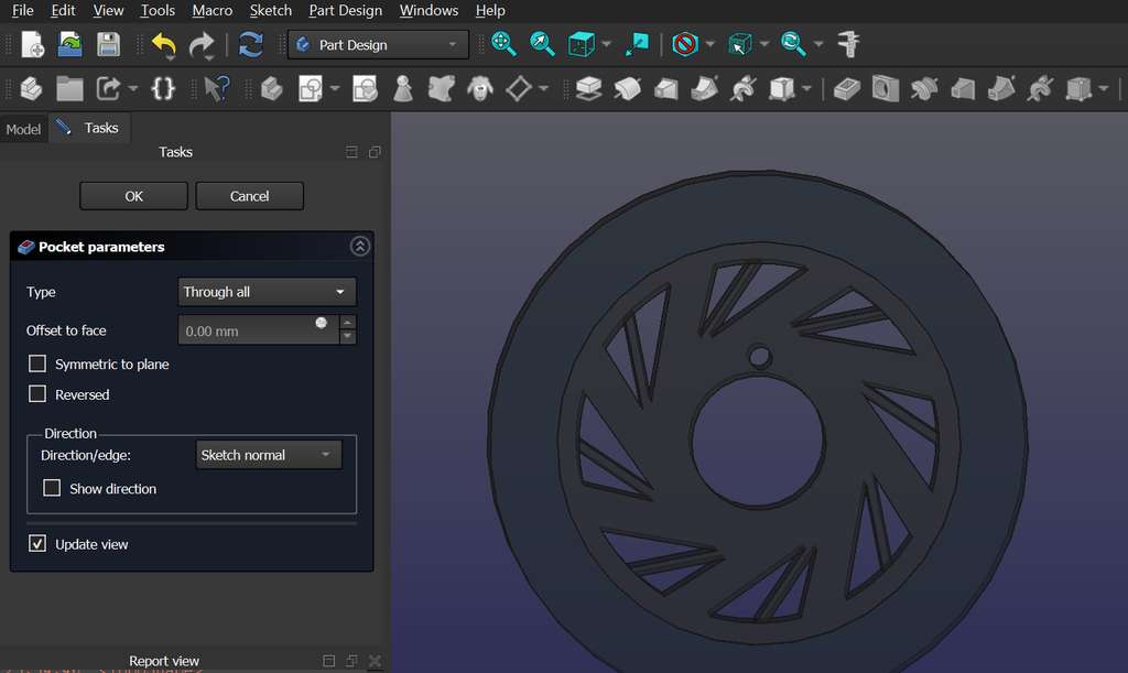
When creating the Pocket, I set the Type to Through All in order to generate a complete hole.
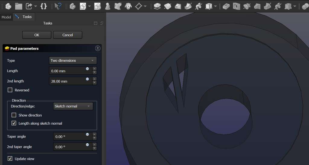
Next, I wanted to create an additional shape inside the existing geometry and fill it. To do this, I designed another shape using a logical construction approach, which can be seen in the images below.
After closing the Sketch, I selected it and applied the Pad tool, setting the Type to Two Dimensions, which resulted in the following shape.
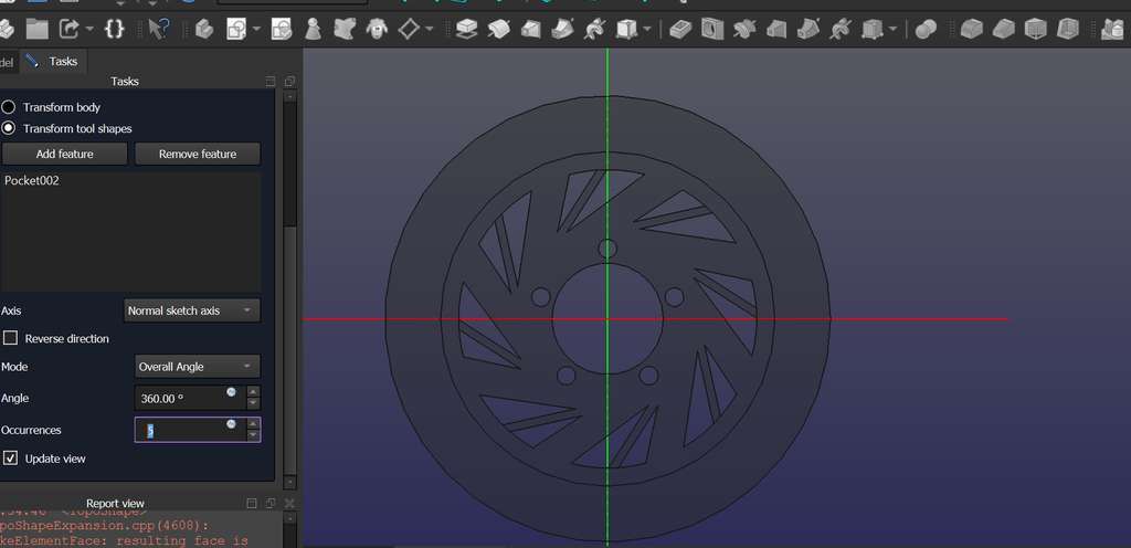
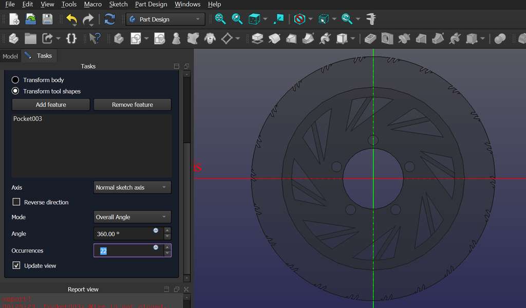
After creating either a Pad or a Pocket, I used the Polar Pattern tool to generate symmetry around the center, with as many repetitions as needed.
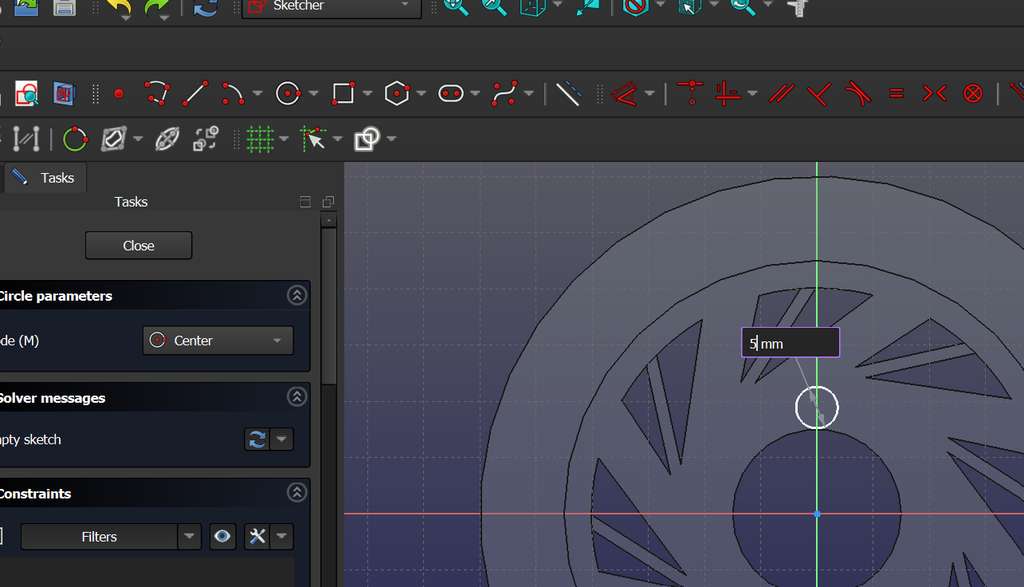
Then, I added another Sketch to create holes near the center. I drew a small circle with a defined diameter and created another Pocket. After closing it, I selected the created Pocket and used Polar Pattern, setting the number of Occurrences to 5.
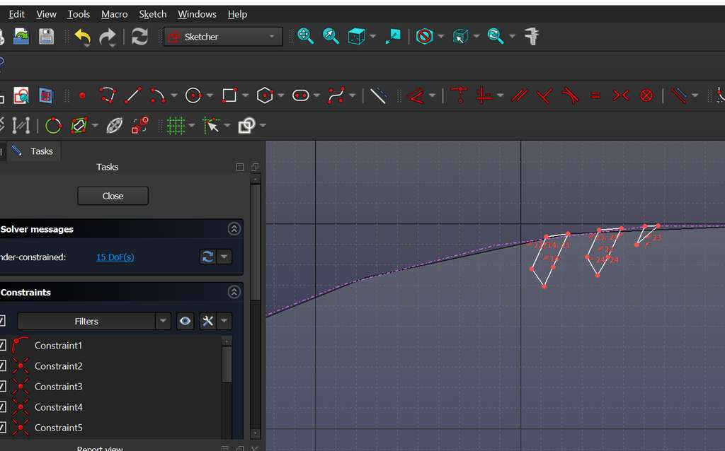
Since I cannot create a Sketch directly on a curved surface (“You need a planar face as support for a sketch!”), I decided to create the patterns on a flat edge first and then apply curvature to that edge.
The images below show this process.
Some of the resources I used are listed below:
- FreeCAD Official Website
- FreeCAD - Ultimate Complete Beginner Tutorial
- FreeCAD Beginner Tutorial: Learn 3D Modeling Basics Step by Step
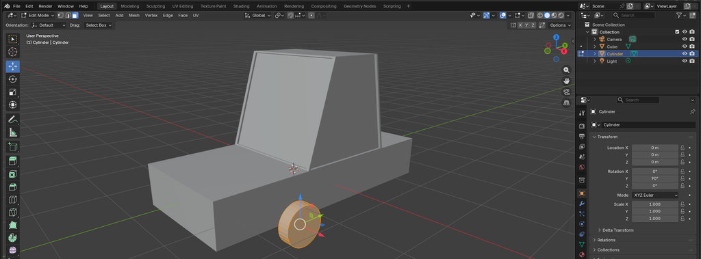
Blender
Now I will also present the steps I took while learning Blender and, at the same time, preparing for my final project.
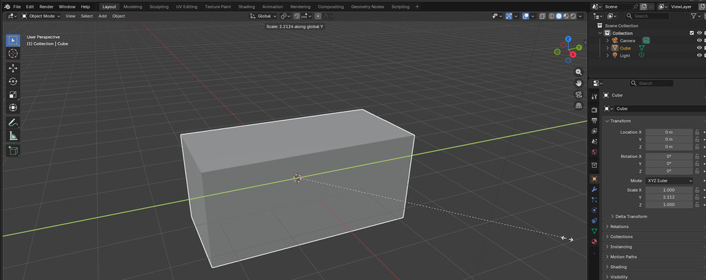
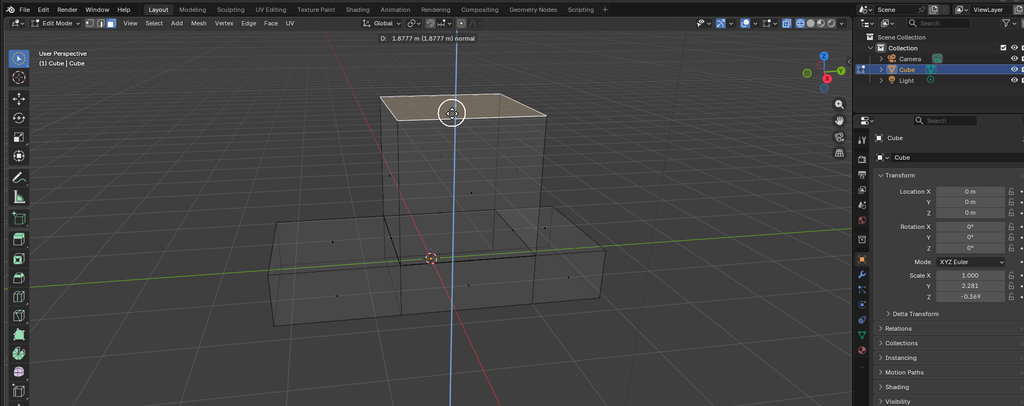
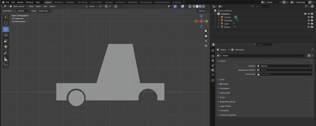
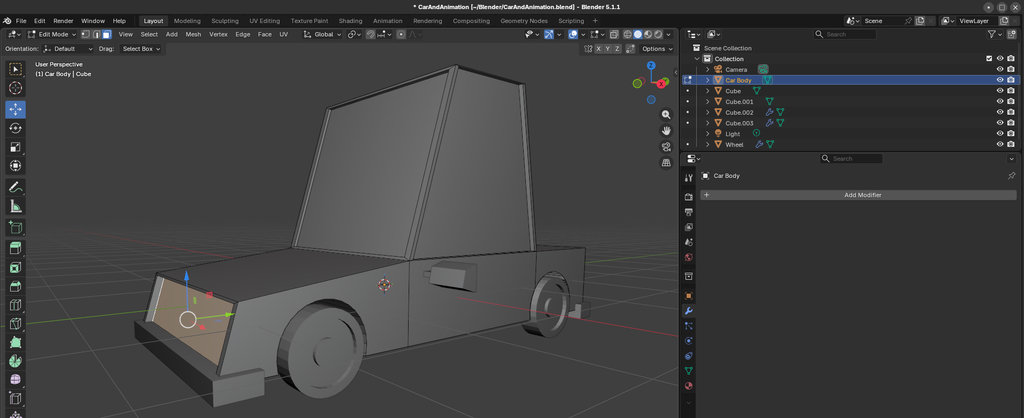
To start, I decided to learn the basic Blender tools by creating a very simple car model.
I installed Blender on my computer using the following command and opened it․
sudo snap install blender --classicThen I started watching many videos explaining how almost any car part can be created from a simple cube.
Here are the links:
- Blender 2.8x Low Poly Car Modeling (easily)
- The World's Easiest Blender Tutorial for Beginners
- Modeling a low poly car | Blender 3.5 Tutorial
I should mention that I learned to experiment much faster in Blender simply by memorizing the following keyboard shortcuts:
🛠️ Basic Navigation- Middle Mouse Button (MMB) (Drag): Orbit the view
- Shift + MMB (Drag): Pan the view
- Ctrl + MMB (Drag): Zoom
- Numpad 7 / 1 / 3: Top, Front, and Right orthographic views
- Numpad 5: Toggle between Perspective and Orthographic
- Numpad . (Period): Frame/focus on the selected object
- ~ (Tilde): Open the View Pie Menu
- Z: Open the Viewport Shading Pie Menu
- Tab: Toggle between Edit Mode and Object Mode
- A: Select all
- Alt + A / Double-tap A: Deselect all
- Shift + A: Add new objects
- X or Delete: Delete selected items
- Shift + D: Duplicate object
- G: Move
- R: Rotate
- S: Scale
- 1 / 2 / 3: Vertex, Edge, and Face selection modes
- E: Extrude
- Ctrl + R: Loop Cut
- Ctrl + B: Bevel
- F: Create face
- M: Merge vertices
- I: Inset faces
- P: Separate geometry into a new object
Now let's move from a simple cube to a simple car.
First, I selected the cube and pressed S (Scale) to give it the size I wanted.
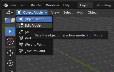
Then I switched from Object Mode to Edit Mode by pressing Tab.
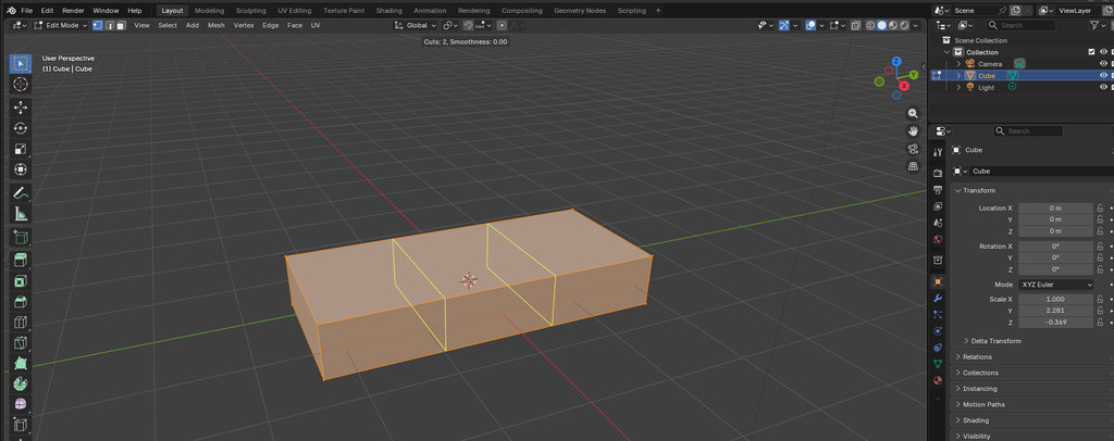
Inside Edit Mode, I selected the cube and pressed Ctrl + R to divide it into sections so I could reshape it piece by piece.
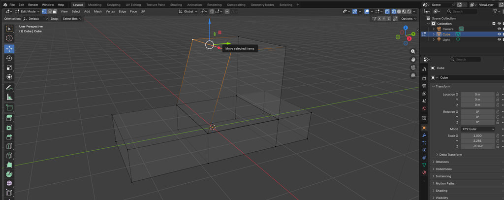
In the top-right corner of Edit Mode, Blender allows selecting three different element types: Vertex, Edge, and Face.
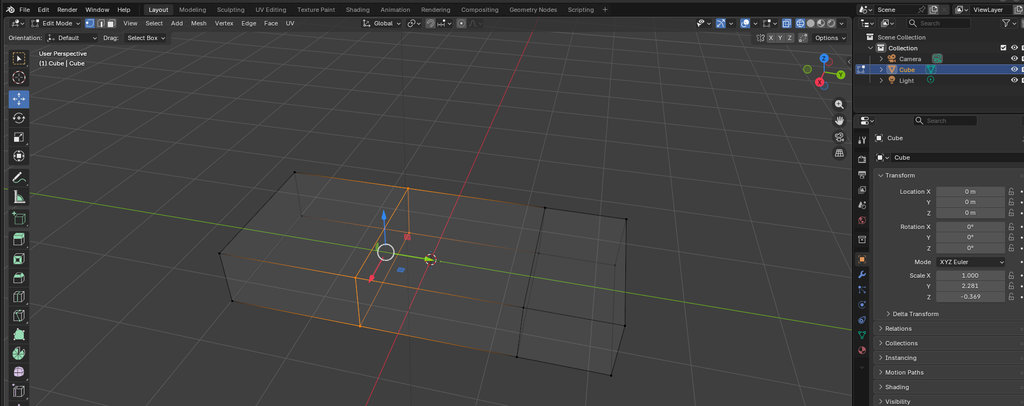
I selected the surfaces or groups of points I wanted to modify and pressed E (Extrude) to pull them into shape.
Here are some examples:
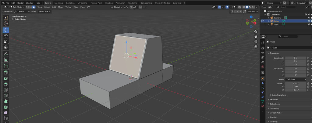
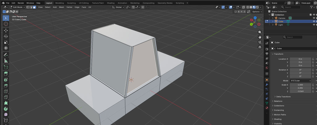
Then, while still in Edit Mode, I selected the appropriate surfaces and pressed I (Inset) to create additional geometry inside the selected face.
After that, I selected the inner face and pushed it inward to create a window effect.
I repeated the same process on all sides.
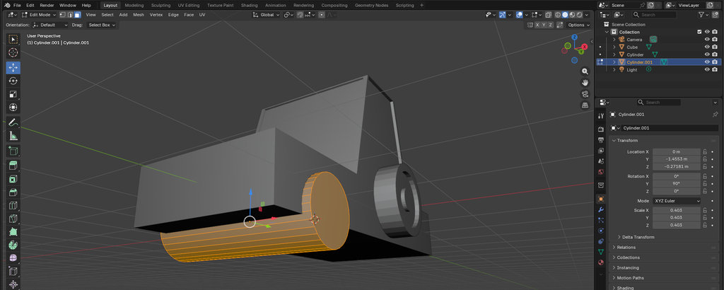
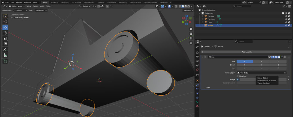
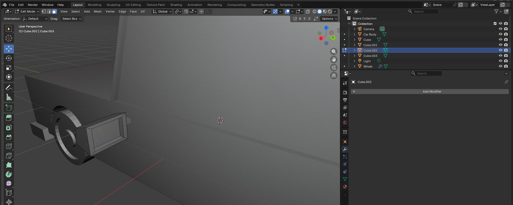
Now it was time to add wheels.
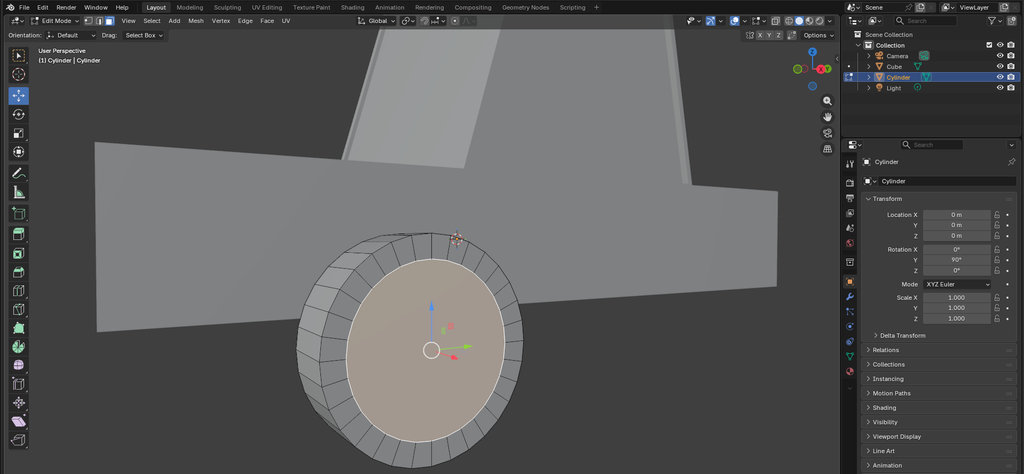
For that, I selected Add → Cylinder and used S to scale it to the desired size.
Using the I and E shortcuts again, I created depth toward the inside.
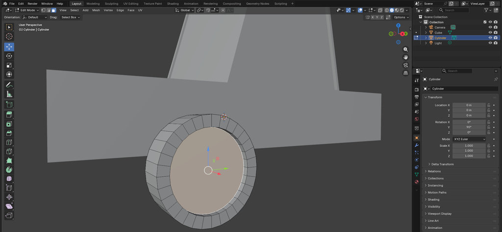
Then I used I and E one more time to create a small ring protruding outward.
At this point, this was simply my own idea of what a wheel should look like. It may not have much connection with reality. 😄
Next, I added another cylinder, this time wider than the car and slightly larger than my wheel.
I used it to remove space from the car body where the wheel should fit.
I selected the car body and, in the lower-right panel, opened: Modifier → Generate → Boolean
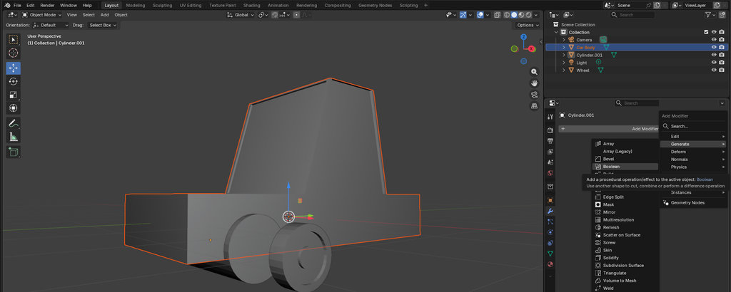
For the Difference operation, I selected the large cylinder using the Eyedropper tool in the Object field.
Then I clicked Apply.
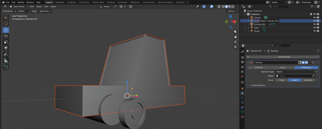
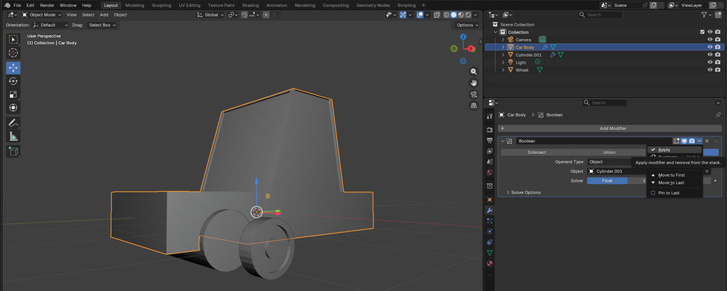
This removed the cylinder shape from the car body.
I repeated the same process on the other side.
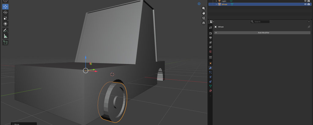
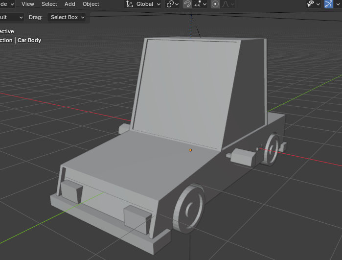
Here is the car from below.
After that, I created another cube and modeled a part that vaguely resembles a car mirror. 😄😄
Then I added some depth to the front section of the car and created another part that resembles car headlights.
And finally, here is a small animation example of the car. This animation is not rendered — I am only showing how the car animation looks inside Blender. Below, I will explain the complete rendering and animation workflow in more detail using a simple cube example.
🎬 Blender: Rendering and Animation
Now I will show how to create a render and animation in Blender.
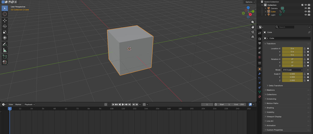
Since I first tried it with my car model, but it required a very long rendering time and my computer was not powerful enough, I will demonstrate the process using a simple cube instead.
For that, I open a new Blender file, and once again I see the default cube in the scene. I will not make any modifications to it; I only want to demonstrate the workflow.
- Creating the Animation
- Configuring the Render Output
- Rendering the Animation
I started by selecting the cube object in the scene and making sure the timeline was set to Frame 1. To define the initial state of the object, I pressed I and selected Location & Rotation, which created the first keyframe.
Next, I moved the timeline playhead to Frame 40 and transformed the cube by changing its position and rotation. After reaching the desired orientation, I inserted a second keyframe using I → Location & Rotation. Blender automatically generated the movement between the two keyframes.
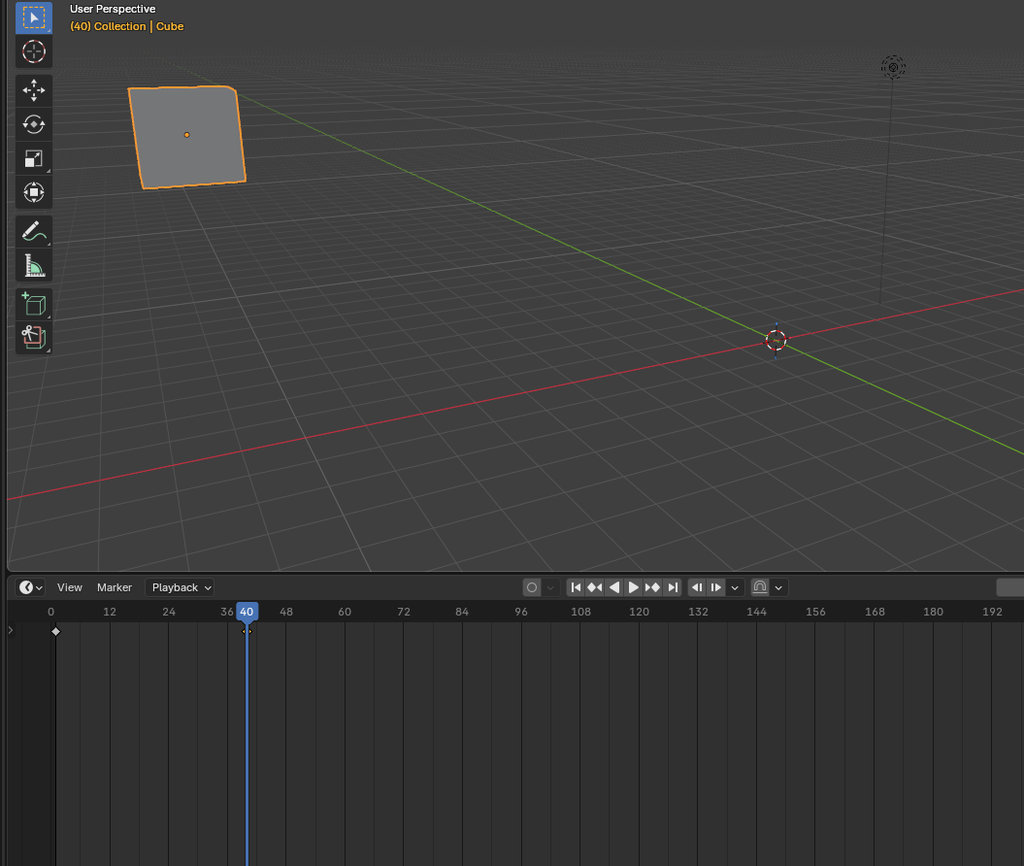
To verify the animation, I pressed the Spacebar and played the timeline. The cube smoothly moved and rotated between the defined positions.
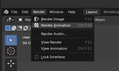
To save the project as a video file and view the animation, I first opened the Output Properties panel and selected a destination folder for the exported file so it would be saved to my desired path. Then I set the Media Type to Video.
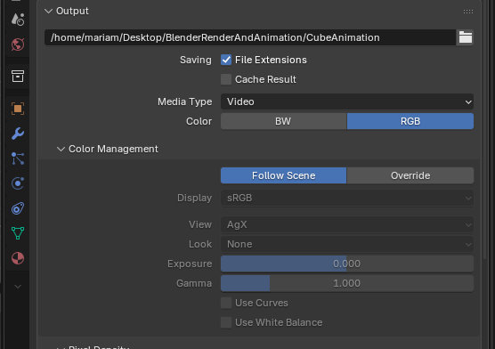
Before starting the final render, I pressed F12 to preview the scene from the camera view and verify the lighting and composition.
Once everything looked correct, I selected Render → Render Animation from the top menu. Blender rendered each frame of the animation and combined them into a single video file, which was saved in the output folder.
Here is the finished animation.
By changing the camera position and rendering again, it is possible to create different animation results. For now, I will share this version.
Although it is a very simple example, it helped me understand the basic workflow of animation and rendering in Blender. By experimenting with different camera angles, object movements, and render settings, I can create more interesting presentations and visualisations for future projects.
Since there is a limitation that each commit should not exceed 10 MB, I generated a Python script to compress images while preserving acceptable visual quality.
I initially asked GitHub Copilot (AI pair programmer) to generate a compression script and then modified the code to match my specific folder structure and workflow. The script processes images from a source directory and saves the compressed versions into the public/images directory of my project in an organized way.
Before compressing the images, I stored all the required raw images in an input-images folder located at the same directory level as the project. Inside this folder, I created separate subfolders for each week, in order to maintain a clean and well-organized workflow.
The Python script automatically:
- Reads images from each weekly subfolder inside
input-images - Creates the corresponding folders inside
public/images - Compresses and resizes the images
- Saves them in the target directory with sequential numbering
Below is the Python code used for image compression:
import os
from PIL import Image

input_folder = "input_images"
output_base_folder = "mariam-daghbashyan/public/images"
base_name = "image"
quality = 60  # JPEG quality
max_size = (1024, 1024)  # resize images if larger than this

# Supported image formats
supported_formats = (".jpg", ".jpeg", ".png")

count = 1

for folder_name in os.listdir(input_folder):
input_subfolder = os.path.join(input_folder, folder_name)
if not os.path.isdir(input_subfolder):
	continue

output_subfolder = os.path.join(output_base_folder, folder_name)
os.makedirs(output_subfolder, exist_ok=True)

for index, file_name in enumerate(os.listdir(input_subfolder), start=1):
	if not file_name.lower().endswith(supported_formats):
		continue

	input_path = os.path.join(input_subfolder, file_name)
	img = Image.open(input_path)

	# Resize if image is too big
	img.thumbnail(max_size, Image.LANCZOS)

	# Convert PNG with transparency to RGB
	if img.mode in ("RGBA", "P"):
		img = img.convert("RGB")

	# new_name = f"{base_name}_{index}.jpg"
	output_path = os.path.join(output_subfolder, file_name)

	try:
		img.save(output_path, "JPEG", quality=quality, optimize=True)
		print(f"Saved: {output_path}")
		count += 1
	except Exception as e:
		print(f"Error saving {output_path}: {e}")

print("✅ Image compression completed!")
ChatGPT prompt:
”Can you provide me with Python code for image compression, without changing image quality”
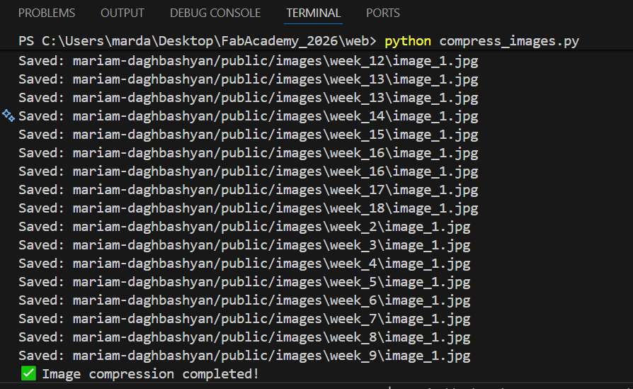
To run the script, I opened the VS Code terminal, navigated to the directory containing the compress-images.py file, and executed the following command: python compress-images.py or py compress-images.py.
Since I don’t have screenshots showing how I run Python code in the Visual Studio Code terminal, I will refer to this YouTube video, which explains the process in detail.
Besides reducing the quality of images, it is also necessary to compress videos to keep the documentation lightweight. For this, Krisjanis Rijnieks recommended using HandBrake, which offers many useful options and does a very good job of reducing file size while maintaining acceptable quality.
I installed HandBrake using the following command:
sudo apt install handbrakeAfter opening my video in HandBrake, I applied the following settings:
- Dimensions → Resolution Limit: 720p HD
- Video Encoder: H.264 (x264)
- Framerate: 24
- Framerate Mode: Constant Framerate
- Preset: Slow
- Constant Quality: RF 26
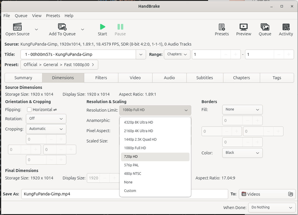
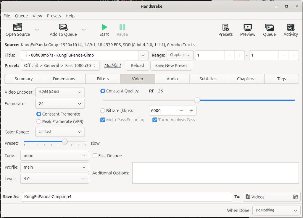
After applying these settings, I clicked the Start button at the top of the window, and HandBrake exported the compressed video to the output path shown at the bottom.
For now, these settings are sufficient, although there is still room for experimentation to achieve even better results.
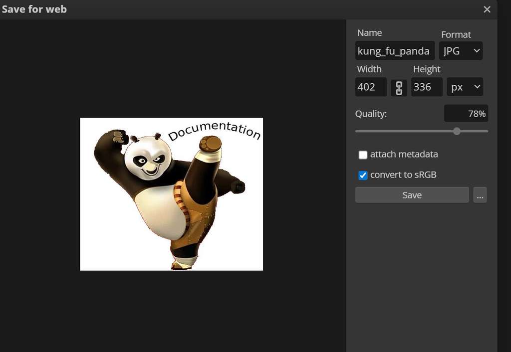
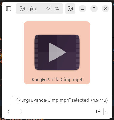
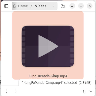
For example, the Kung Fu Panda video shown above was originally 4.9 MB. After applying these settings and exporting it through HandBrake, the file size was reduced to 2.3 MB.
I would also like to mention that I watched the following videos to better understand how HandBrake works and how to choose the right compression settings:
- How to Compress Video Without Losing Quality | Handbrake Tutorial
- How To Use Handbrake To Compress Video File Size - Handbrake Tutorial
These tutorials helped me understand the balance between file size and video quality when preparing media for documentation.
conclusion
During this week, I explored multiple digital design and media-processing tools, including OpenSCAD, Inkscape, FreeCAD, Blender, GIMP, and HandBrake. I learned how to create parametric designs in OpenSCAD, convert 3D models into 2D SVG files, prepare designs for digital fabrication, and experiment with basic 3D modeling workflows in Blender.
I also learned how to optimize images and videos for documentation using GIMP and HandBrake, which helped me better understand the balance between media quality and file size.
This week helped me better understand the importance of parametric design, the workflow between different software tools, and how to troubleshoot common modeling and documentation issues. The skills gained here will be directly useful for developing and improving components of my final project throughout Fab Academy.
Individual assignment
AI prompt:
“And when finished second week.”