Computer-Controlled Machining
Group Assignment
Here is the link to our group project page. I worked with fellow Fab Academy students Max Negrin, McKinnon Collins, and Oliver Abbot. My jobs for this week's group assignment were to test the ShopBot's runout and perform a toolpath test. You can find my documentation for these tests on the student page.
Individual Project - Table and Stand Design with CNC Machining
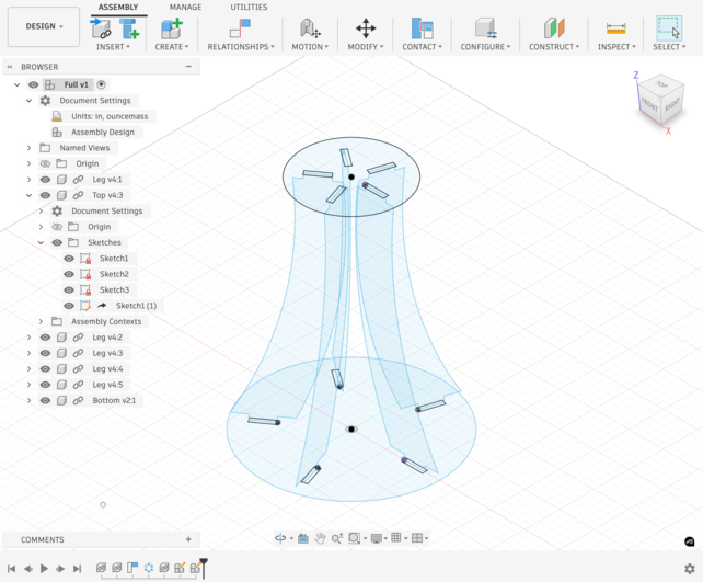
For this week's assignment, I designed a table and stand with five curved legs using Fusion 360 and then prepared it for CNC machining using Aspire. The final design features outward-curving legs that connect to both a top and bottom circular platform.
Designing in Fusion 360
Understanding Parametric Design
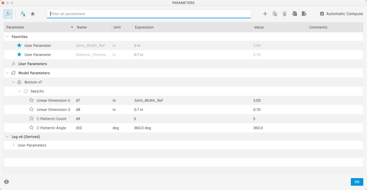
To create this design, I utilized Fusion 360's parametric design capabilities. Parametric design is a process where you define parameters (user-defined variables) that control the dimensions and properties of your design. These parameters are useful because they allow you to make changes to your model quickly and efficiently without having to manually edit each individual dimension. What makes parametric design so powerful is that if you change a parameter value, all features that depend on that parameter will automatically update. This is particularly useful when designing multiple similar components, as you can create one component with parameters and then easily modify it for different versions or variations. For example, if I needed to change the material thickness across my entire table design, I could simply update one parameter and all five legs would automatically adjust to match.
Creating the Leg Component
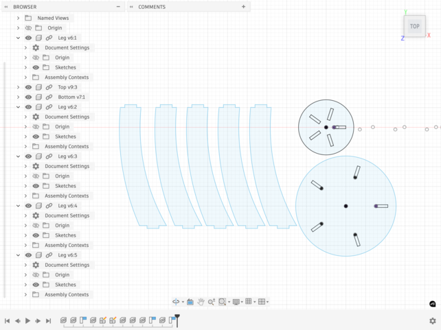
To start the design process, I decided to make the leg as a separate parametric component and create the other four legs as copies later. This approach allowed me to refine the leg design and then duplicate it efficiently across the entire assembly. Working with a single component first meant that I could test and perfect the design before committing to the full assembly.
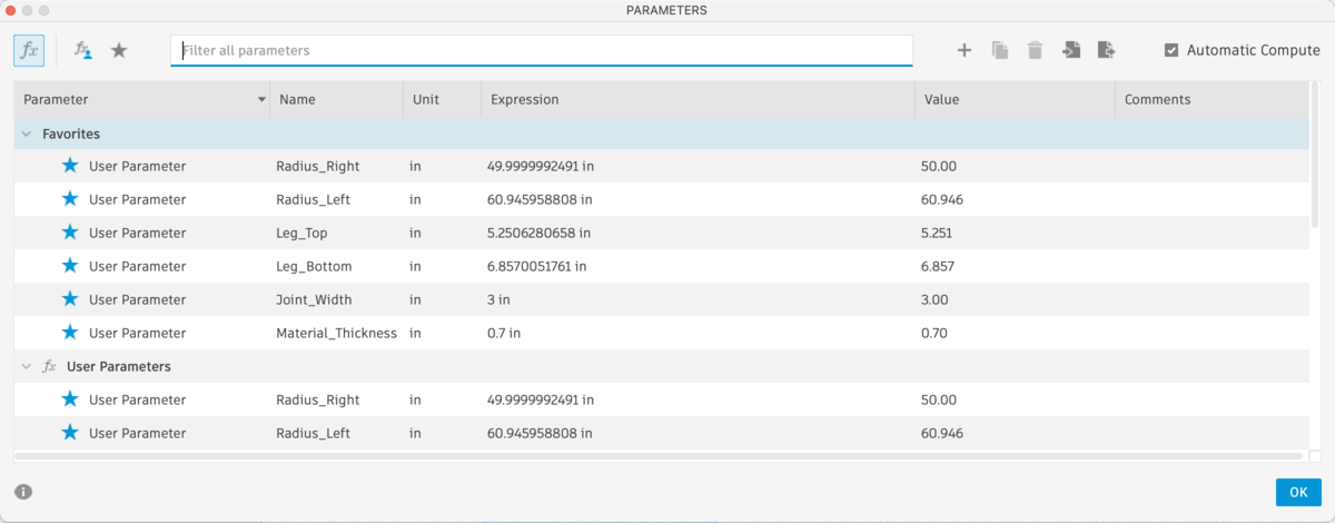
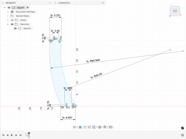
To create the leg, I needed to define several key parameters that would control the leg's geometry. I started by thinking about what aspects of the leg needed to be adjustable. The leg features a curved shape that extends both upward and downward, and it needs to connect to both the table top and the table bottom through joinery. With this in mind, I defined the following parameters:
Radius_Right- Controls the curvature on the right side of the legRadius_Left- Controls the curvature on the left side of the legLeg_Top- Defines the length of the top section of the leg that connects to the table topLeg_Bottom- Defines the length of the bottom section of the leg that connects to the table bottomJoint_Width- Controls how wide the joint is that connects to the table top and bottomMaterial_Thickness- Defines the joint length, which translates directly to material thickness
These parameters allowed me to easily adjust the leg design without manually changing individual dimensions. I created the leg profile by using curves and then extruding them to create the joinery slots. The key insight here is that by linking all these dimensions to parameters, I made it so that if I needed to change the material thickness, I could simply update the Material_Thickness parameter and the entire leg would adjust accordingly.
Creating the Table Top
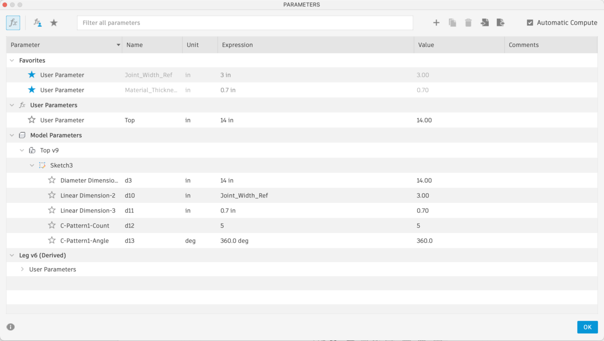
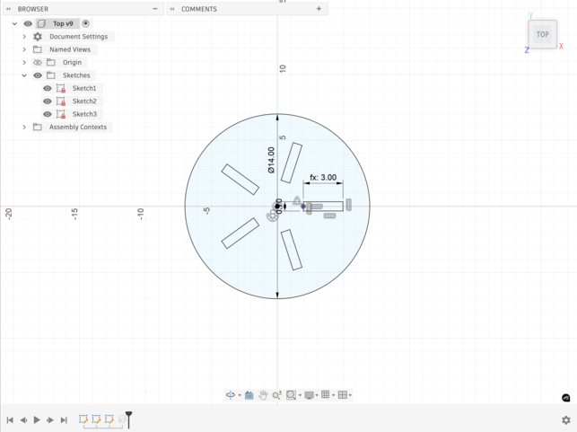
Once the leg was complete and I was satisfied with its geometry, the next step was to create the table top as a separate component. To start, I created a new component by clicking File > New Component. I sketched a circle with a diameter of 14 inches, which would serve as the outer profile of the table top.
The table top needed to accommodate the leg joints, so I had to create 5 slots that would hold the leg joinery. The size and position of these slots were critical because they needed to match the leg joints exactly. Rather than manually entering dimensions, I used the Insert Derive tool. This tool allowed me to pull parameters directly from the leg component into the top component. Specifically, I derived the Joint_Width and Material_Thickness parameters from the leg so that the slots in the top would automatically adjust if I ever changed those parameters in the leg.
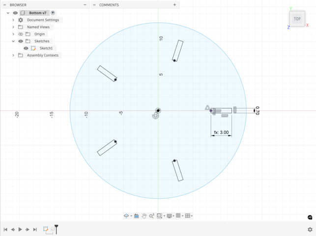
When creating the slots, I had to arrange them in a circular pattern around the table top. I sketched each slot to match the dimensions of the leg joint, making sure they were spaced 72 degrees apart (360 degrees divided by 5 legs). This planning was important because it ensured that each slot would line up perfectly with its corresponding leg when I assembled everything later.
Creating the Table Bottom
Similar to the top, I created a bottom component as a separate parametric component. I started by creating a new component and sketching a circle, but this one needed to be larger to accommodate the curved legs. The bottom ended up having a diameter of 25.451 inches. Like the top, the bottom also contains 5 slots to fit the leg joints, and I used the Insert Derive tool to link the joint dimensions to the leg component.
The main difference with the bottom component was that it needed to be oriented differently. Since the legs curve outward, the bottom is positioned below the legs, which meant I had to think carefully about how the joinery would work from this different angle. However, by using the derived parameters, I ensured that any changes to the leg dimensions would automatically propagate to the bottom slots as well.
Assembly and Circular Pattern
With all the components created, the next step was to assemble them. To do this, I decided to try inserting the leg into the top component by right-clicking on the leg component and selecting Insert into Current Design. This action prompted me with a dialog screen that asked whether I wanted to create a new assembly or convert the top design to an assembly. Since I wanted to keep the top as a standalone component and have a separate assembly that contained all three components, I chose to create a new assembly.
Once the new assembly was created, I positioned each component in the correct location relative to the origin. I inserted the top component at the top, the bottom component at the bottom, and a single leg component in the center. This gave me a starting point where I could see how the components would interact with each other and verify that the joints aligned properly.
To create the five-legged design, I then used the Circular Pattern feature on the leg component. Rather than manually positioning each leg, I right-clicked on the leg component in the model tree and selected Circular Pattern. This opened a dialog where I could specify the number of copies I wanted (4 additional copies, making 5 total) and the center axis of the pattern. I set the pattern to repeat around the Z-axis so that the legs would be evenly distributed around the table. Fusion 360 then automatically created 4 duplicate legs spaced equally around the center axis, with each leg rotated 72 degrees from the previous one.
With the legs properly distributed around the top and bottom, I was able to verify that each leg joint matched up with its corresponding slot. The parametric design meant that all the dimensions were already aligned, so the assembly came together without any gaps or misalignments. Everything fit together perfectly, which was a testament to the power of parametric design and derived parameters.
You can download my finished design here.
Exporting for Machining
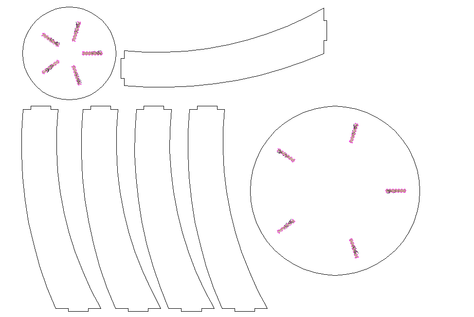
Once the Fusion 360 design was complete and I was satisfied with the assembly, I needed to export it in a format that the CNC machine could understand. I exported the design as a .dxf file, which is a standard file format for CNC machines and CAM software. To do this, I navigated to File > Export in Fusion 360 and selected .dxf as the file format. This gave me options to choose which components to export and how to organize them in the file.
Before exporting, I made sure to flatten the design or export it in a way that would work with the CNC software. The .dxf file preserves all the geometry from my Fusion 360 design, including the leg profiles, the circular top and bottom, and all the joinery slots. With the .dxf file exported, I then loaded it into Aspire to prepare the toolpath for CNC machining.
Aspire and Toolpath Preparation
After exporting my design from Fusion 360, the next step was to bring it into Aspire. Aspire is a CAM software that is used to prepare digital designs for CNC machining. While Fusion 360 was where I created the actual geometry of my table design, Aspire was the software that allowed me to translate that geometry into machine-readable cutting instructions for the ShopBot. In other words, Aspire helped bridge the gap between the digital design and the actual machining process. It allowed me to set up my material, choose tools, define toolpaths, and make sure that my design could actually be cut out of wood on the CNC machine.
To move my design over, I first exported the Fusion 360 design as a .dxf file and then opened that file in Aspire. As soon as I imported it, Aspire prompted me with a setup screen that asked for the dimensions of my material as well as the Z Zero Position. Since I found a new piece of wood to cut from, I measured it before entering the values into Aspire. The wood measured 48" in the x direction, 96" in the y direction, and 0.7" in the z direction. For the Z Zero Position, I set it to Machine Bed.
This setup step was important because it defines the physical boundaries of the wood that the ShopBot will cut from. If the material dimensions are entered incorrectly, the toolpaths may not match the actual stock, which could cause parts to be cut in the wrong place or even outside the usable area of the wood. Setting the Z Zero Position to Machine Bed tells Aspire to measure cut depths starting from the bed of the machine rather than the top surface of the material.
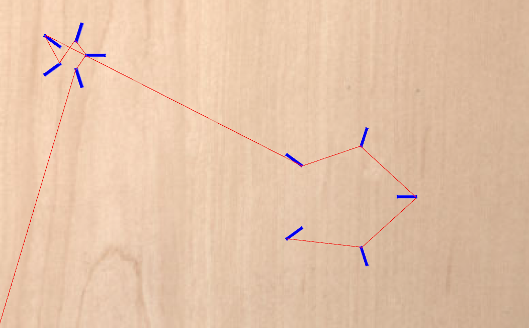
Once the material was set up, I then went on to create my toolpaths. The first toolpath I created was a profile toolpath for the outlines of my design. A profile toolpath is a type of toolpath where the machine cuts directly along the edge of a selected vector. This type of toolpath is especially useful when cutting out the outer shape of a part because it follows the perimeter of the design rather than clearing out the inside area. In my case, before I could even calculate this first toolpath, I ran into an issue because some of the lines in my design were not connected properly. This caused Aspire to recognize them as open vectors.
Open vectors are line segments or shapes that do not form a fully closed boundary. This becomes a problem in machining because Aspire needs complete, closed shapes in order to generate many types of clean and predictable toolpaths. To fix this, I used the Join Vectors tool to manually close each open vector. Once all of the outlines were fully connected, Aspire was able to recognize the geometry correctly.
From there, I selected each outline, went to the Toolpaths tab, and selected 2D Profile Toolpath. I then set the tool to a 1/8" end mill and set the machine to cut on the vector Outside and Right. For the Cut Depth, I entered 0.7" so that it would match the thickness of the material. Setting the cut depth equal to the material thickness ensures that the tool cuts all the way through the wood rather than leaving any uncut material at the bottom.
I also added tabs to the toolpath and placed three tabs on each object. Tabs are small uncut sections of material that intentionally hold a part in place while the rest of the profile is being cut. They are extremely useful in CNC machining because once a part is fully cut free, it can shift, vibrate, or get caught by the spinning end mill. By leaving tabs behind, the part stays attached to the stock until the machining process is complete, which makes the cut safer and more accurate.
Once all of those settings were in place, I calculated the toolpath.
Here are my settings for the profile toolpath.
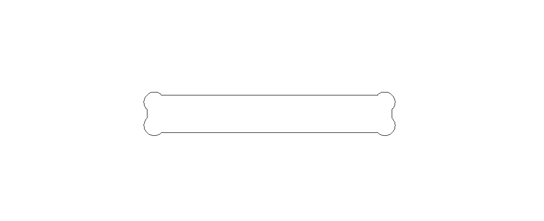
The next toolpath I created was a pocket toolpath for each joint socket in the design. Before creating this toolpath, I first had to add dog bones to each joint socket so that the joints would physically fit after machining.
In CNC machining, a dog bone is a small circular relief cut added to interior corners. Since end mills are round, they cannot cut a perfectly sharp inside corner. Without a relief feature, square tabs will not fully seat into square-looking sockets because the corners still contain leftover material from the tool radius. Dog bones solve this by removing material at the corners so that flat-edged joints can fit properly during assembly.
To add these in Aspire, I used the Fillet tool, selected Dog-Bone Fillet, and set the radius to about 0.13. I then applied this to each corner of each joint socket. Since every joint socket has four corners, each one received four fillets to complete the dog-bone pattern.
Once the dog bones were complete, I selected each joint socket, went to the Toolpaths tab, and clicked Pocket Toolpath.
A pocket toolpath is used to clear material from inside a closed boundary to a specified depth. In contrast, a profile toolpath follows along the edge of a vector, either inside, outside, or directly on the line. The profile toolpath is ideal for cutting outer part boundaries, while the pocket toolpath is better for joint sockets because sockets need their interior area removed so that mating parts can slide in and seat properly. If I had used only a profile for the socket interiors, it would not clear the full area the joint needed.
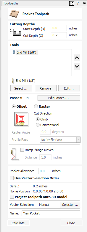
For this pocket toolpath, I started by setting the Cut Depth to 0.7" again so that the tool would cut all the way through the material. I also selected the 1/8" end mill again so that the machine would not need a tool change between operations. I set the Cut Direction to Climb and set the number of passes to 14. At the time, this seemed reasonable for the cut, but this ended up being a critical mistake later because each pass took a long time, which caused each individual joint socket to take over 10 minutes to machine. All other settings were kept as default, and then I calculated the toolpath.
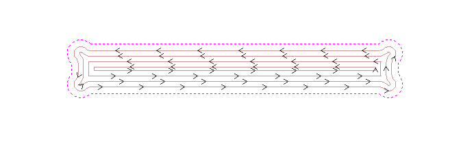
Here is a pocket toolpath up-close.
Here are my settings for the pocket toolpath.
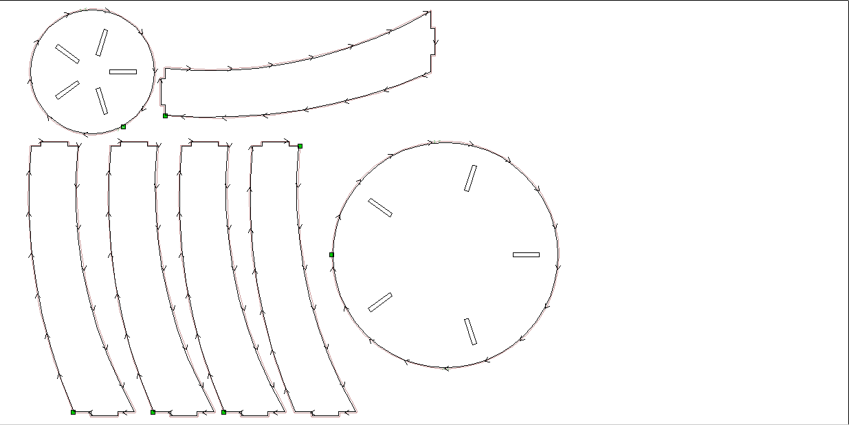
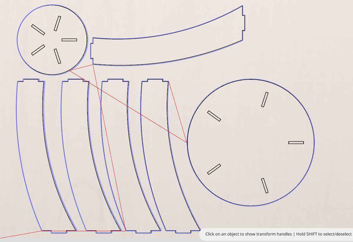
After both toolpaths were created and validated, I exported the final Aspire file as a .crv3d and saved it to my drive for machining.
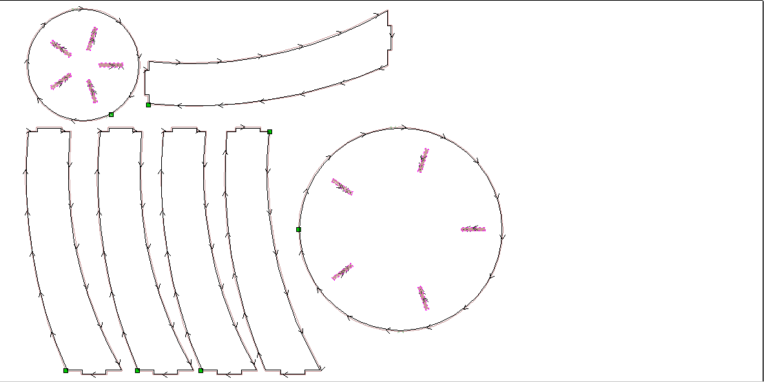
Here is what the final Aspire design looked like.
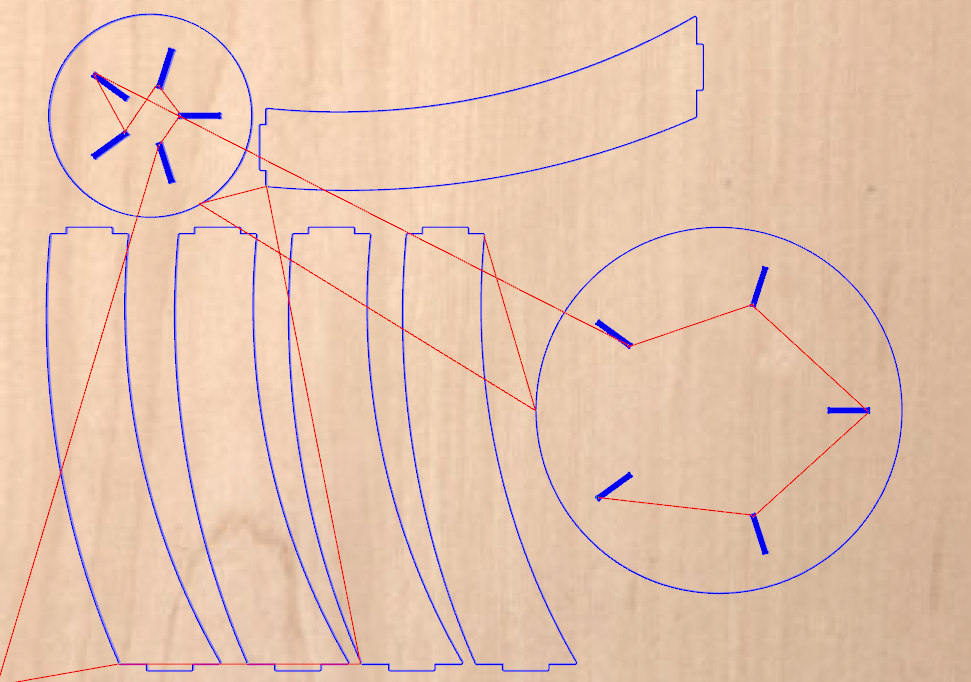
You can download my Aspire design file here.
ShopBot Process
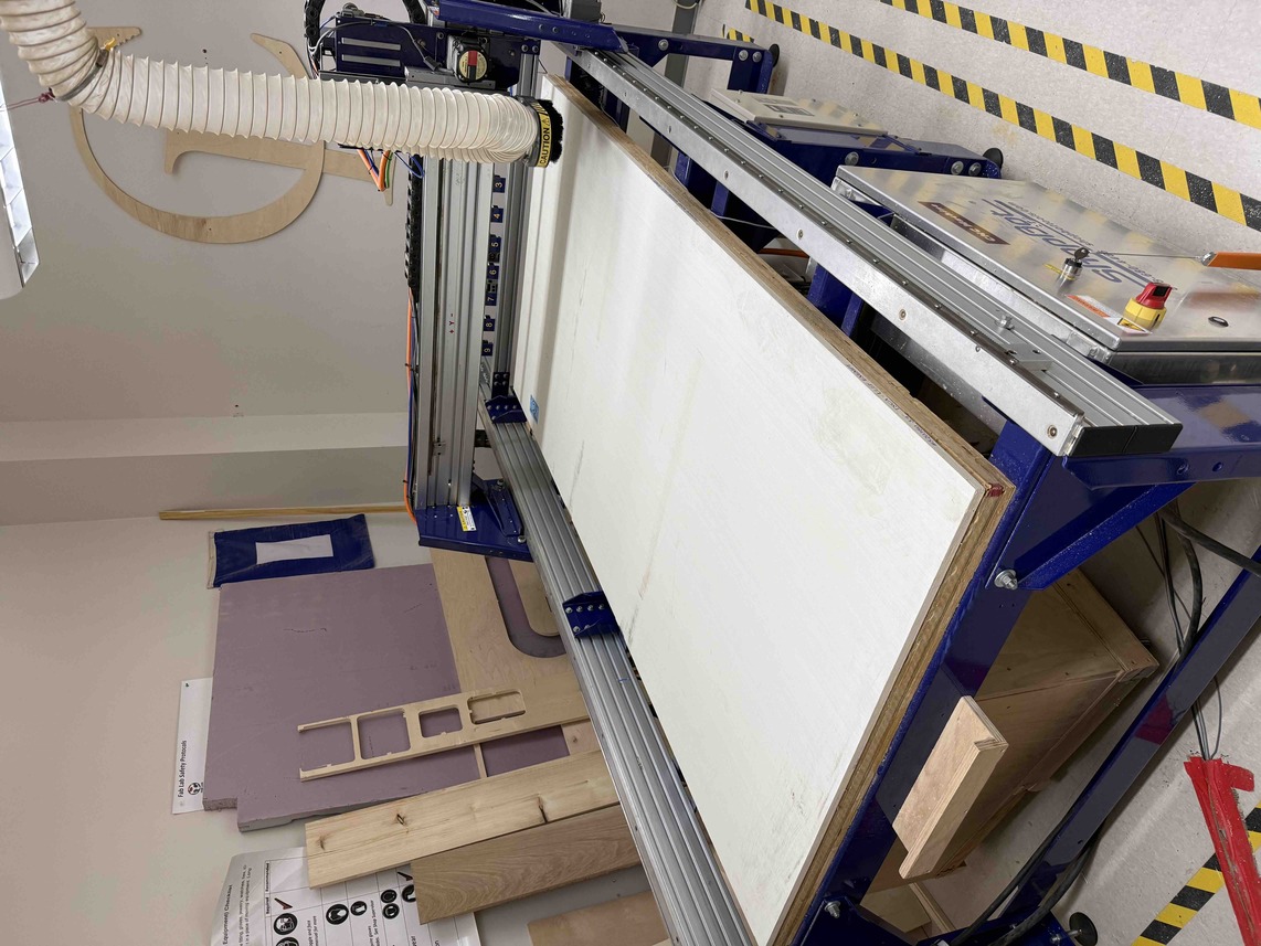
The next step was to move from the digital design process into the actual cutting process on the ShopBot. A ShopBot is a large CNC router that is designed to cut sheet material such as plywood, MDF, and other wood products. Its purpose is to take a digital toolpath and machine it into a real physical object. In the context of this assignment, the ShopBot was the machine that would cut my table components out of wood based on the Aspire toolpaths I had already prepared.
To start this process, I first got my wood board and secured it to the ShopBot bed using a plastic nail gun. This step was very important because the material needs to be held firmly in place while the machine is cutting. If the board shifts even slightly, the cuts can become inaccurate or the bit can crash into the material in an unintended way. The wood measured about 96" in the x direction, 48" in the y direction, and 0.7" in the z direction.
Once the wood was secured, I opened my Aspire design on the computer connected to the ShopBot. At this point, my teacher, Mr. Dubick, advised me that it would be smart to begin with a test joint before committing to the entire design. This was good advice because it meant I could verify that the joints would actually fit once cut, instead of risking an error across the whole table.
To do this, I made two new toolpaths in Aspire. The first was a pocket toolpath for the 5 joint sockets in the tabletop, and the second was a profile toolpath for one leg of the table. After creating those toolpaths, I previewed them to make sure they appeared functional and then exported them from Aspire.
The ShopBot has its own software, so I used that software when beginning the cut. The first thing I did was home the ShopBot's bit to the origin by typing C3. There was no need to jog it manually because the ShopBot already recognized its distance from the machine bed. After that, I clicked [F]ile > [P]art File Load, selected the test pocket toolpath, and then clicked enter in the popup to begin the cut. Before doing this, however, it was important to physically start the drill using the green remote button on the ShopBot. If the spindle is not started first, the machine can still move through the path without actually cutting the material correctly.
From there, I waited for the design to cut. It ended up taking an extremely long time, around 15 to 20 minutes per joint socket. After a while, Mr. Dubick told me that I should switch to a profile toolpath for my remaining sockets instead of continuing to use the pocket toolpath. This made sense because the pocket path was removing far too much material too slowly for what I actually needed.
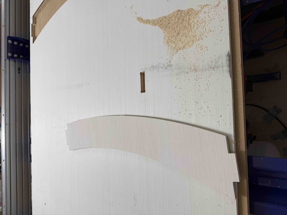
I ended up making a fatal error during this step, however. When I made the profile toolpath, I accidentally set the Z Zero Position to Material Surface instead of Machine Bed. This caused the bit to crash into the wood, and the cut was essentially ruined. To fix this, I went back, changed the Z Zero Position to Machine Bed, and then re-ran the cut.
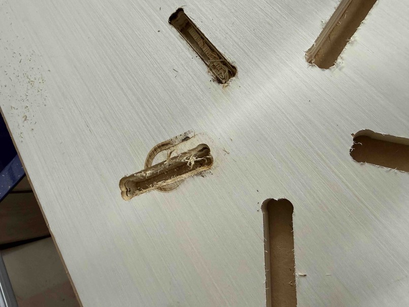
The image above shows the failed test result. More specifically, it shows how the two profile-cut joints were drastically different from the three pocket-cut joints. This difference made it very obvious that the profile toolpath was working much more efficiently for the type of slot I was trying to make.
After that, I went ahead and ran the profile toolpath to cut the test leg. Once the leg was cut, I discovered another fatal error. This time, I realized that I had set the joint thickness parameter to the wrong thickness in Fusion 360. I had it set to 0.46", which was the thickness of my old wood board that I had originally planned to use, instead of 0.7", which was the actual thickness of the wood board I ended up cutting. The same problem applied to my joint sockets, which were also 0.46" wide. This meant that the joint could not fit at all.
Luckily, this was only a test joint, so I did not lose too much progress from the mistake. Since the problem was caught early, I was able to go back into Fusion 360, fix the joint thickness parameter so that it matched the real material thickness of 0.7", and then redo the Aspire toolpath creation process from there.
Finalizing Aspire Toolpaths and ShopBot Workflow
Before finalizing my Aspire toolpaths, I made sure to set the number of passes for the pocket toolpaths to 7, which is exactly half of the original number of 14. In machining, a "pass" refers to a single traversal of the cutting tool through the material at a specified depth. Instead of cutting all the way through in one go, the machine removes material in multiple, shallower layers—each one called a pass. By cutting the number of passes in half, I was able to significantly reduce the time it took to machine each joint socket, since the tool was removing more material per pass and making fewer total trips. Every other setting was essentially kept the same.
I also made sure that the Z Zero Position was set to Machine Bed to avoid making the same mistake as before, and I repositioned each toolpath so that they would cut on fresh wood and not interfere with portions of wood that had already been cut earlier.
Once I was satisfied with those changes, I saved my design and once again opened it on the computer assigned to the ShopBot. From there, I remade two test toolpaths: one pocket toolpath for a single joint socket and one profile toolpath for a single leg, and then exported both toolpaths for testing.
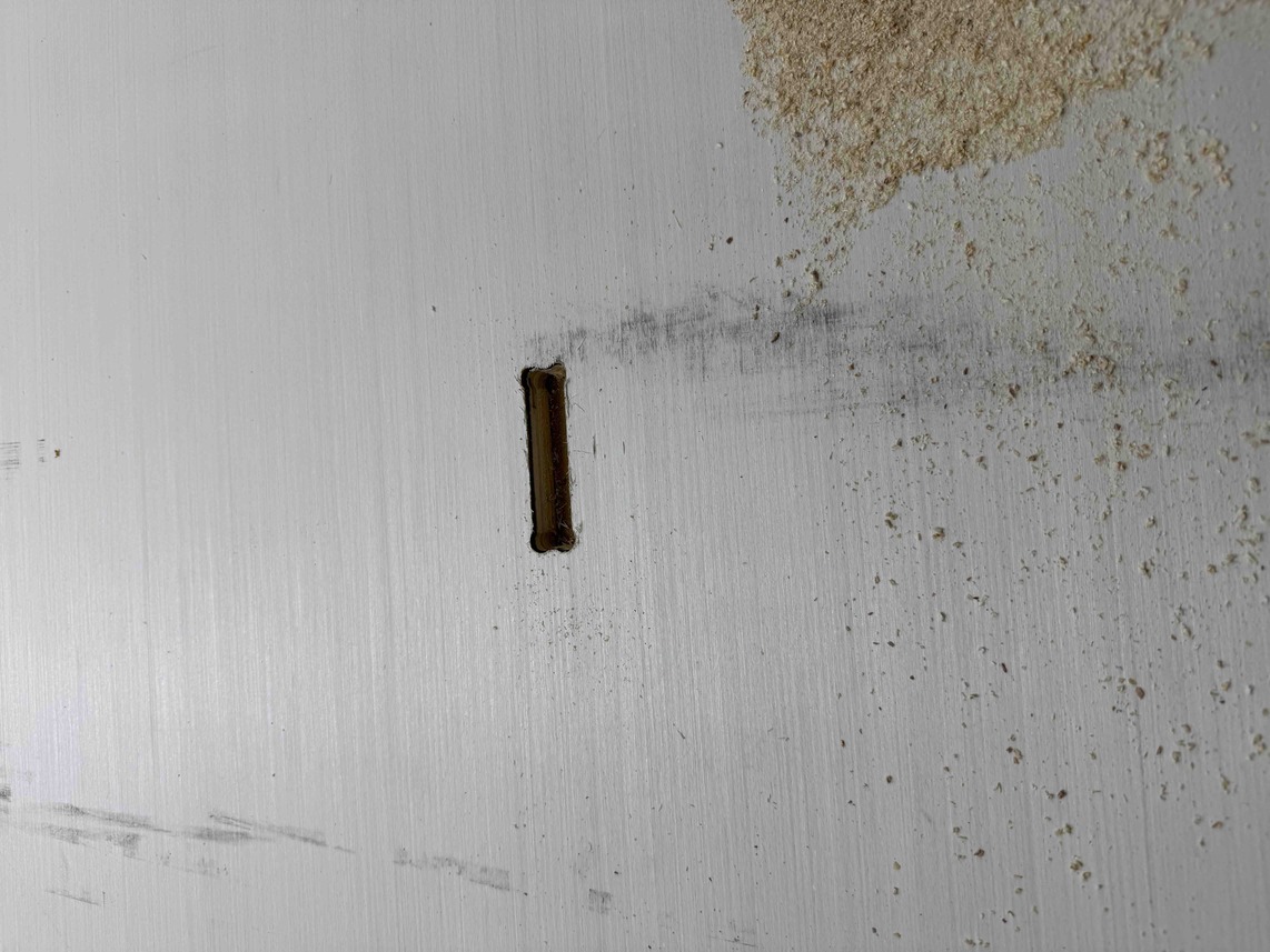
I then followed the normal ShopBot workflow to home the machine, load my file, and run the cut. The first toolpath I ran was the test pocket toolpath. After a bit, here is how it turned out.
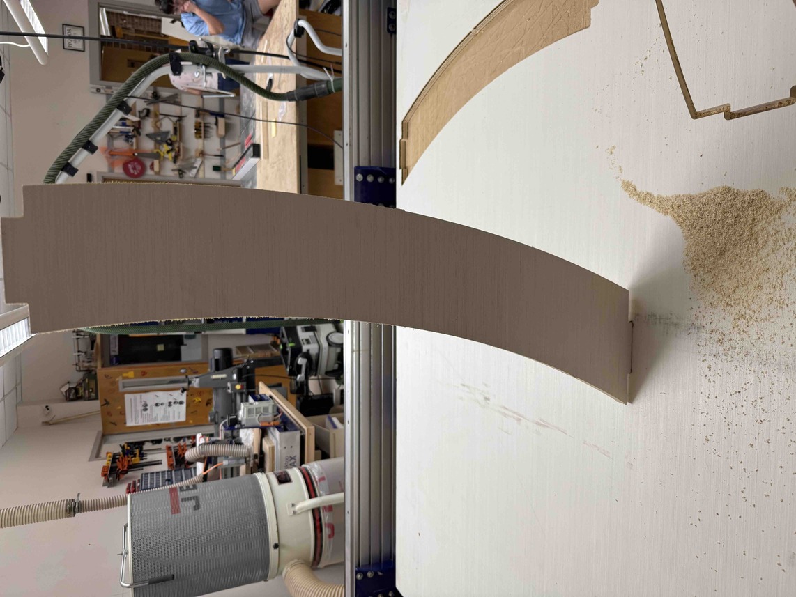
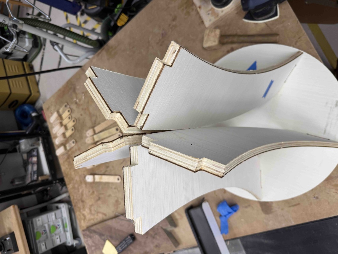
After that, I went through the same workflow again to cut a table leg, which was the test profile toolpath. Here are the leg and socket tests side by side.
I then inserted the leg into the joint socket to see if it worked, and found that it actually fit, but was extremely tight. My instructor, Mr. Dubick, told me that a tight fit is actually a good thing because it means I would not have to glue or nail each joint, and the design would be structurally sound on its own.
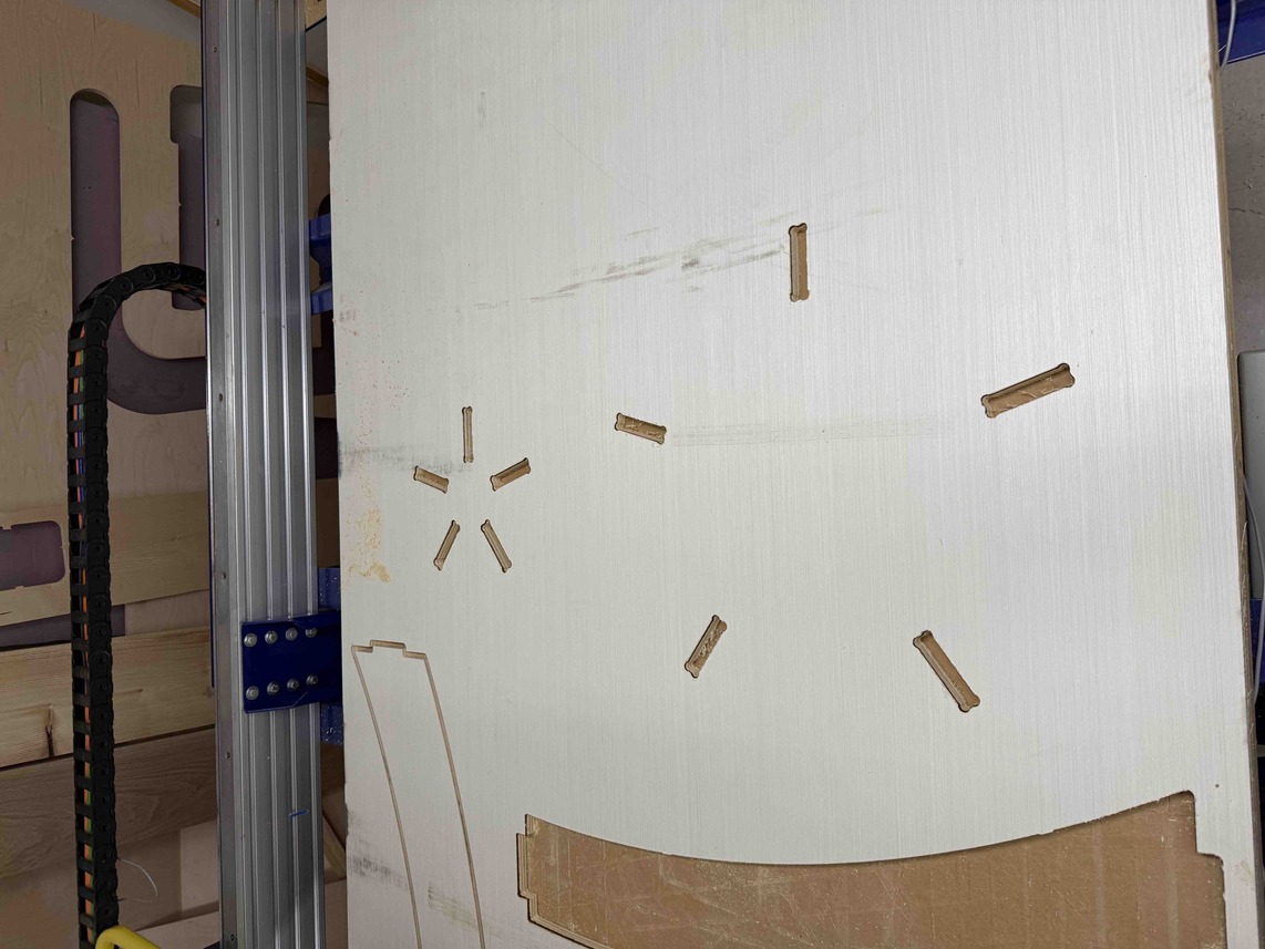
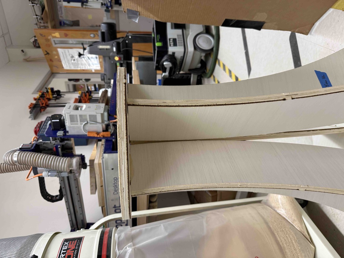
Once I confirmed that the joints were functional and that the parameters were correct, I then ran the actual toolpaths. I followed the same workflow to first cut each joint socket. Here is how they turned out.
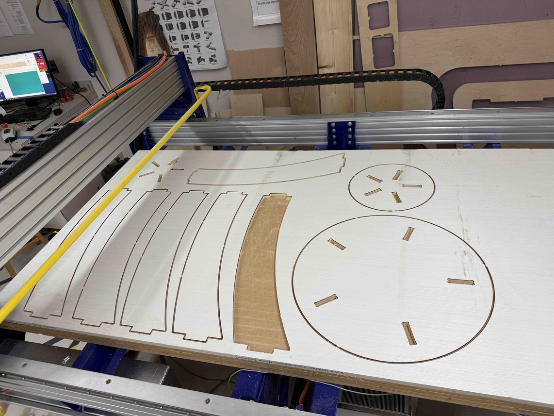
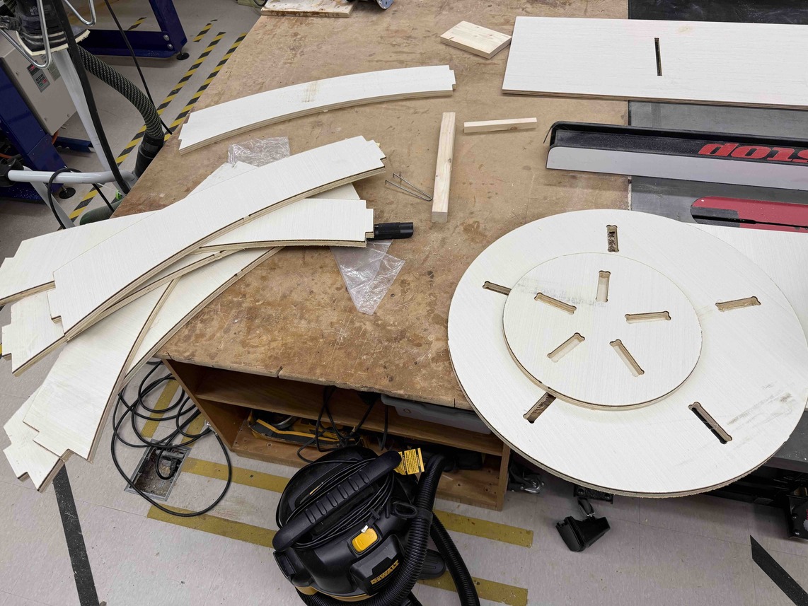
I then ran the profile toolpaths to cut each leg, the base, and the tabletop. This finalized my pieces. Here is the finished cut.
Removing the Parts
With all the cuts complete, the final step of the ShopBot process was to remove each piece from the wood sheet. Because I had added tabs to each profile toolpath, none of the parts were fully separated from the stock yet. To free each piece, I used a utility knife to carefully cut through each tab one by one. Once all the tabs on a given piece were cut, I was able to lift it cleanly out of the sheet.
Sanding and Assembly
Sanding
With all the pieces freed from the sheet, the next step was to sand them down before attempting assembly. For this, I used two types of sanders: a triangular orbital sander and a rotary sander.
The triangular orbital sander was particularly useful for getting into tight corners and along flat edges. Its pointed tip allowed it to reach areas that would otherwise be impossible to sand with a larger tool, which made it ideal for working along the inside edges of the joint sockets. The rotary sander, on the other hand, was better suited for covering larger, flatter surfaces quickly. Its circular pad spins at high speed and removes material faster than the orbital, which made it great for smoothing out the broad faces of the legs and platforms.
The main purpose of sanding in this project was to ensure that the joints would actually fit together. When the ShopBot cuts through wood, it leaves behind a slightly rough surface on the cut edges. In a press-fit design like mine, where every joint needs to slide into a socket cleanly, even a small amount of roughness or excess material can make the fit impossibly tight. Sanding the joints and sockets removes that excess material and smoothens the surfaces so that everything seats properly.
I started by sanding down the inside of each joint socket in the tabletop and bottom platform. The goal here was to smooth out the interior walls so that the leg joints would have a clean surface to press against. I then sanded each joint on every leg itself, removing material evenly from all four sides so that the joint dimensions would be closer to the intended tolerance.
After sanding the first joint, I tested it by pressing it into one of the joint sockets to see how the fit had improved.
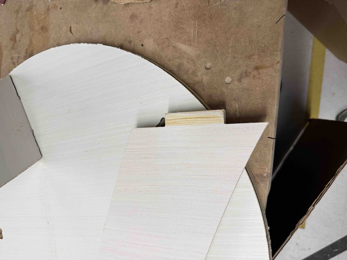
The image above shows what a joint should look like after a round of sanding. The edges are noticeably smoother and the corners are slightly broken in, which helps guide the joint into the socket without catching.
Testing the First Joint Fit
With the first joint sanded, I placed it into its corresponding socket to test the fit. It took a bit of hammering to get it fully seated, which was expected given how little tolerance there was between the joint and the socket. Despite the tight fit, the joint did go in and held firmly once it was fully pressed down. This confirmed that the sanding process was working as intended.
One thing I noticed right away was that the joint sat slightly above the surface of the bottom platform rather than sitting flush. This happened because I had forgotten to add dog bones to the corners of the joints themselves. The joints had square corners, but the pockets that received them had slightly rounded corners from the bit radius, even after the dog bones were added to the sockets. This small discrepancy meant the joint could not fully drop to the bottom of the socket, leaving it raised just a bit above the platform surface.
Assembling the Full Table
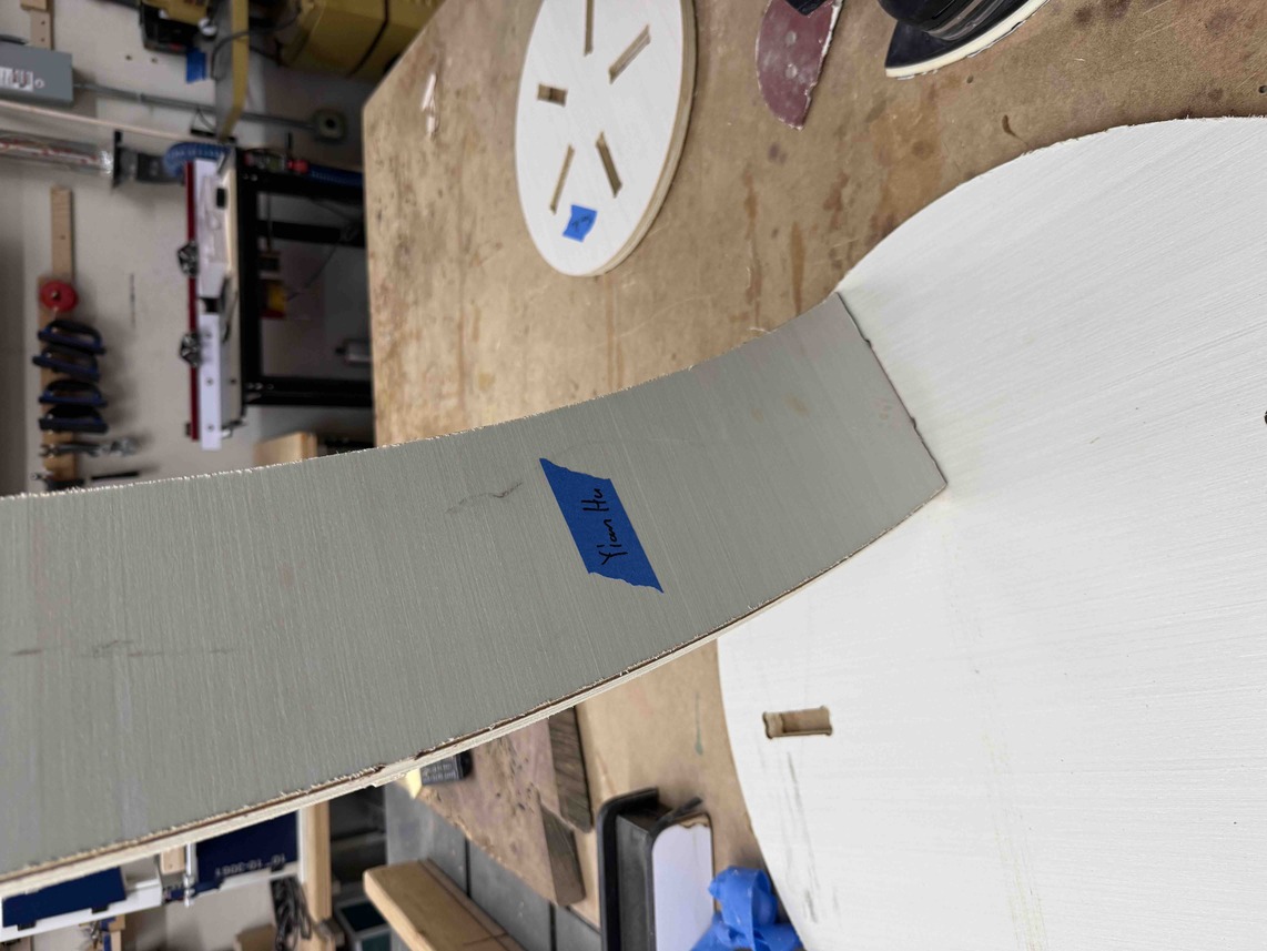
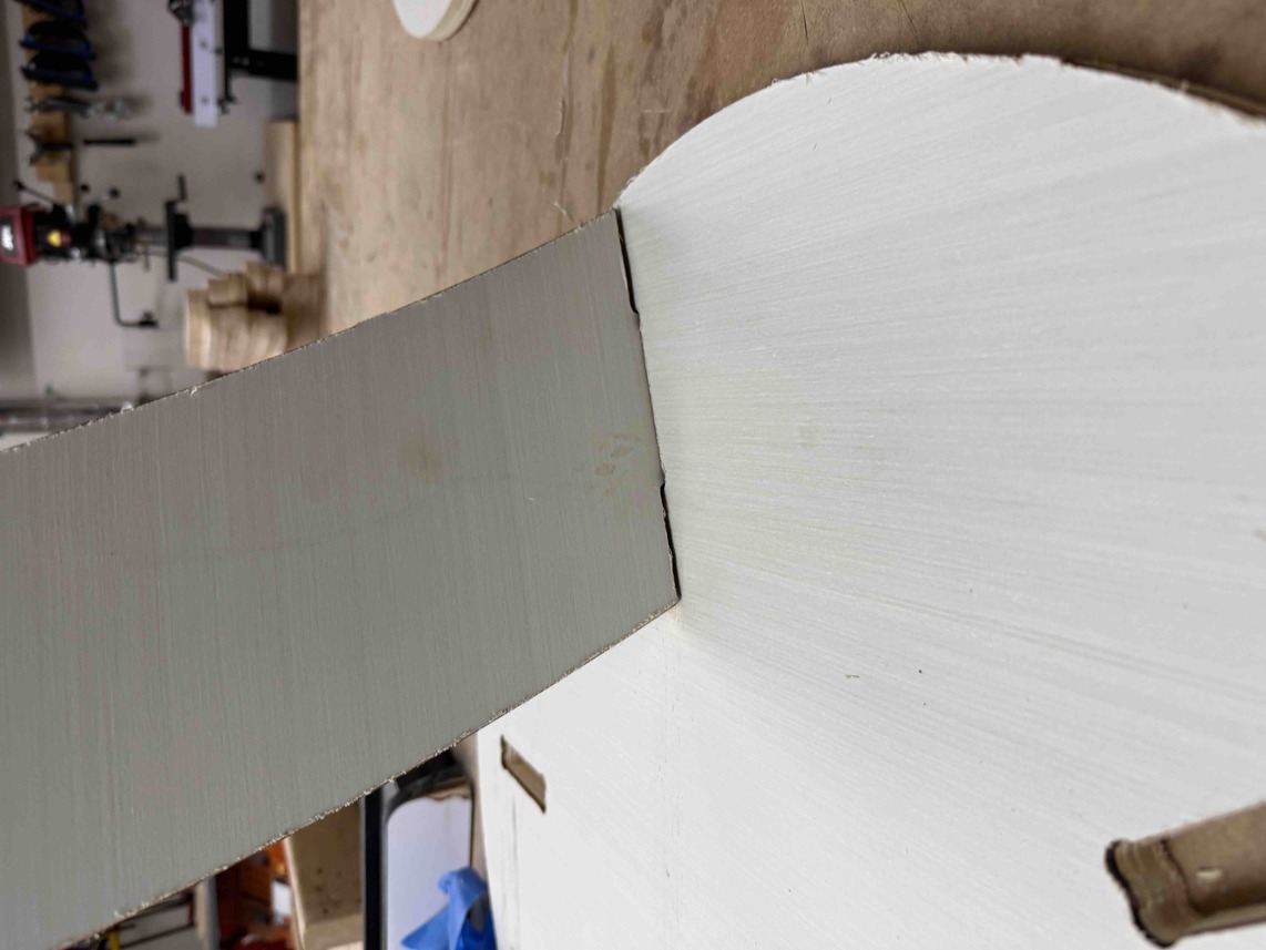
With the first joint tested and confirmed to work, I followed the same sanding and testing process on every other joint. Once all the joints were sanded, I began fitting the legs into the bottom platform. Each leg required some hammering to fully seat, but once they were in, they held together extremely tightly. Despite the effort it took to assemble, this was actually a positive outcome because it meant the table did not need any nails or glue to stay together. The press-fit design alone was enough to keep everything structurally secure.
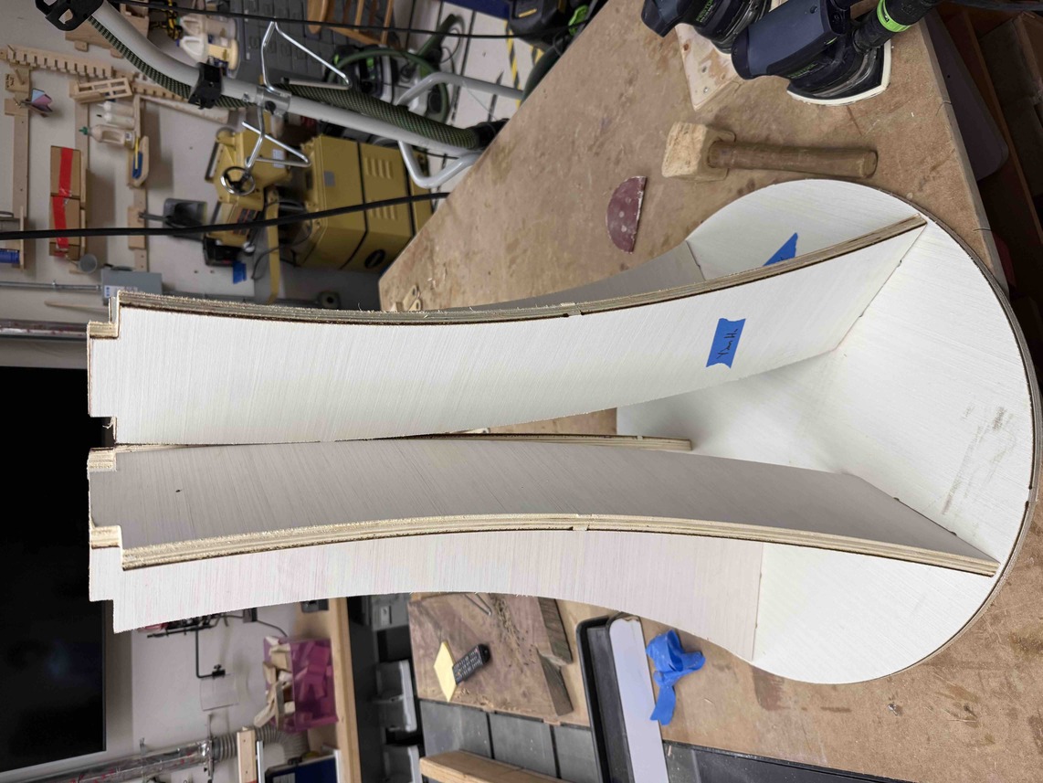
With the legs seated in the bottom platform, the next critical step was to check the alignment of the top joints before placing the tabletop. It was important that all five top joints were lined up properly and pointing in the right direction, because misaligned joints would make it impossible to slot the tabletop down evenly. If even one joint was rotated or tilted, it would not line up with its corresponding socket in the tabletop, and the entire top would sit crooked or not go on at all.
Sanding the Top Joints
Unfortunately, I made the mistake of not sanding the top joints before placing the legs into the bottom platform. This meant that once the legs were locked in, I was forced to sand each of the top joints while they were still attached to the standing structure, which was much more awkward and tedious than sanding them on a flat surface. I had to hold the sander at different angles and work around the structure rather than just laying a piece flat and going over it.
I worked through each top joint with a trial-and-error process, sanding a bit, testing the tabletop fit, sanding more if it still did not seat, and repeating until all five joints were accepted by their sockets. After several rounds of fitting and sanding, I was finally able to press the tabletop down onto the leg assembly. The fit was slightly uneven in places, but it was good enough that the table was fully secure and did not wobble or flex.
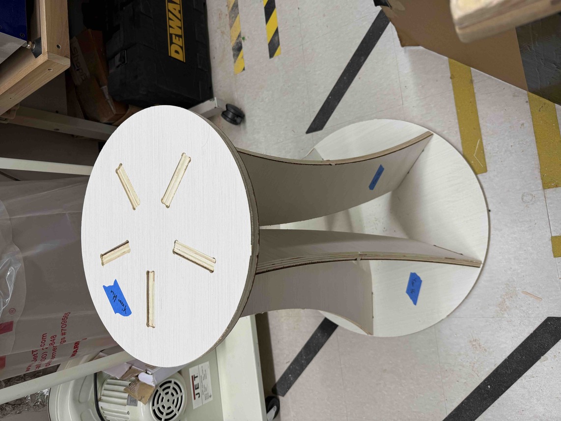
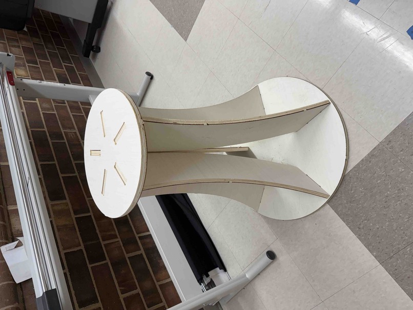
With the tabletop in place, the table was finished.
Reflection
Week 7 was by far the most involved and physically demanding week of Fab Academy so far. Between designing the table in Fusion 360, setting up and running toolpaths in Aspire, operating the ShopBot, and then sanding and assembling the final piece by hand, there were a lot of individual steps that each had their own challenges.
The biggest recurring theme of this week was making mistakes and having to go back and fix them. I ran into errors at almost every stage — the wrong joint thickness parameter in Fusion 360, the Z Zero Position set to Material Surface instead of Machine Bed, the pocket toolpath taking far too long, and forgetting to add dogbone fillets to the joint corners. Each of these mistakes cost time and in some cases required re-running entire toolpaths from scratch. That said, I think the process of catching and fixing each of those errors was ultimately more valuable than getting everything right the first time would have been. It forced me to actually understand why each setting mattered rather than just following a set of steps without thinking about them.
One of the more important lessons I took away from the ShopBot workflow was how critical it is to verify every single parameter before running a cut. The Z Zero Position mistake was a perfect example of this. It was a single incorrect dropdown selection in Aspire, but it caused the bit to crash directly into the wood and ruined the cut entirely. Going forward, I will make it a habit to do a full settings review before exporting any toolpath, specifically checking things like Z Zero, tool selection, start and end depth, and pass count.
The parametric design workflow in Fusion 360 was another highlight of this week. Being able to define a single Joint_Thickness parameter and have every dependent feature update automatically when I corrected it from 0.46" to 0.7" saved a significant amount of time. Without that, I would have had to manually go back and adjust each individual joint dimension, which would have been both tedious and error-prone. It also reinforced how important it is to name and organize parameters clearly at the start of a project, since a well-structured parameter table makes it much easier to debug and modify a design later on.
On the assembly side, the sanding process was more involved than I expected. Getting the joints to the right tightness required a lot of back-and-forth testing, and the fact that I had already assembled the bottom platform before sanding the top joints made the whole process significantly harder. That is something I would change if I were to do this project again — sanding all joints completely before beginning any assembly would save a lot of time and frustration.
One thing I also noticed during assembly was the black burning along the top edge of each cut, which is visible in the image of the aligned top joints above. After thinking through what had happened, my best explanation is that the cutting depth I entered in Aspire was either slightly less than the actual thickness of the wood, or my initial measurement of the material was slightly off. Either way, the result was the same: on the final pass, the bit was forced to go deeper than intended to finish the cut, which caused the wider shoulder of the end mill — the part of the bit above the cutting flutes — to contact the top surface of the wood. Since that section of the bit is not designed to cut material, the friction generated heat and left behind the burned discoloration along the top edge. The cuts were still functional and the joints fit correctly, but the burning was a visible sign that the depth settings were not perfectly dialed in. Going forward, I will take extra care to double-check my material thickness measurement and verify that the cut depth in Aspire matches it exactly before starting any toolpath.
Despite all of the setbacks, I am genuinely happy with how the table turned out. The press-fit joinery held together without any glue or fasteners, the curves on the legs came out exactly as I had designed them in Fusion 360, and the overall structure is solid and stable. It is a good reminder that even when a project does not go perfectly, careful problem-solving and persistence can still produce a result worth being proud of.