Computer-Controlled Cutting
Group assignment
For this part, I worked with fellow Fab Academy students Max Negrin, McKinnon Collins, and Oliver Abbot. Our group assignment for this week was to characterize our lasercutter's focus, power, speed, rate, kerf, joint clearance and types.
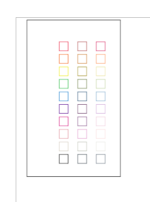
My job for this assignment was to run the speed, power, and frequency test. You can find my documentation for this process on my group's documentation page. Here is what my design for the test looked like.
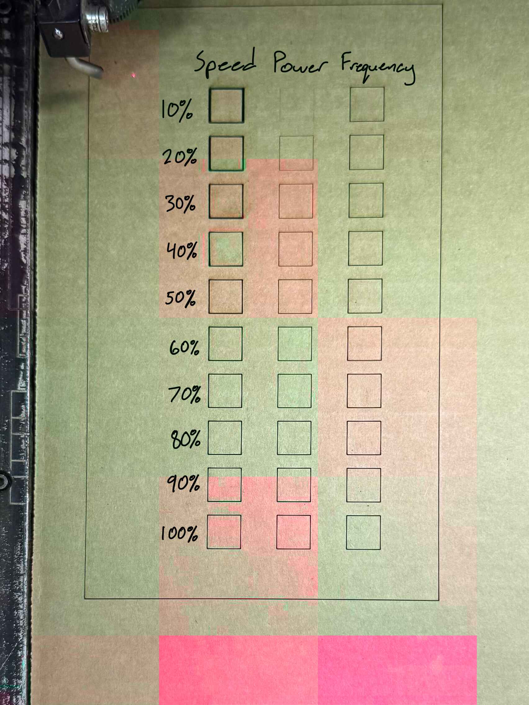
Here is the test outcome.
Vinyl Cutting
Using Silhouette Studio
To design my vinyl sticker, I utilized Silhouette Studio as it is the software built specifically for the Cameo vinyl cutters in our Fab Lab.
I first installed the MacOS version of Silhouette Studio through its offical website. After following the installation steps, I was able to open the software and begin a new design from there.
I chose to design the San Francisco 49ers logo because they are my favorite NFL team and have a relatively simple color scheme and design. To start, I found a png image of the 49ers logo through a quick google search. I made sure that the image had a transparent background so that I could avoid having to remove it later. Here is what the original image looked like.
![]()
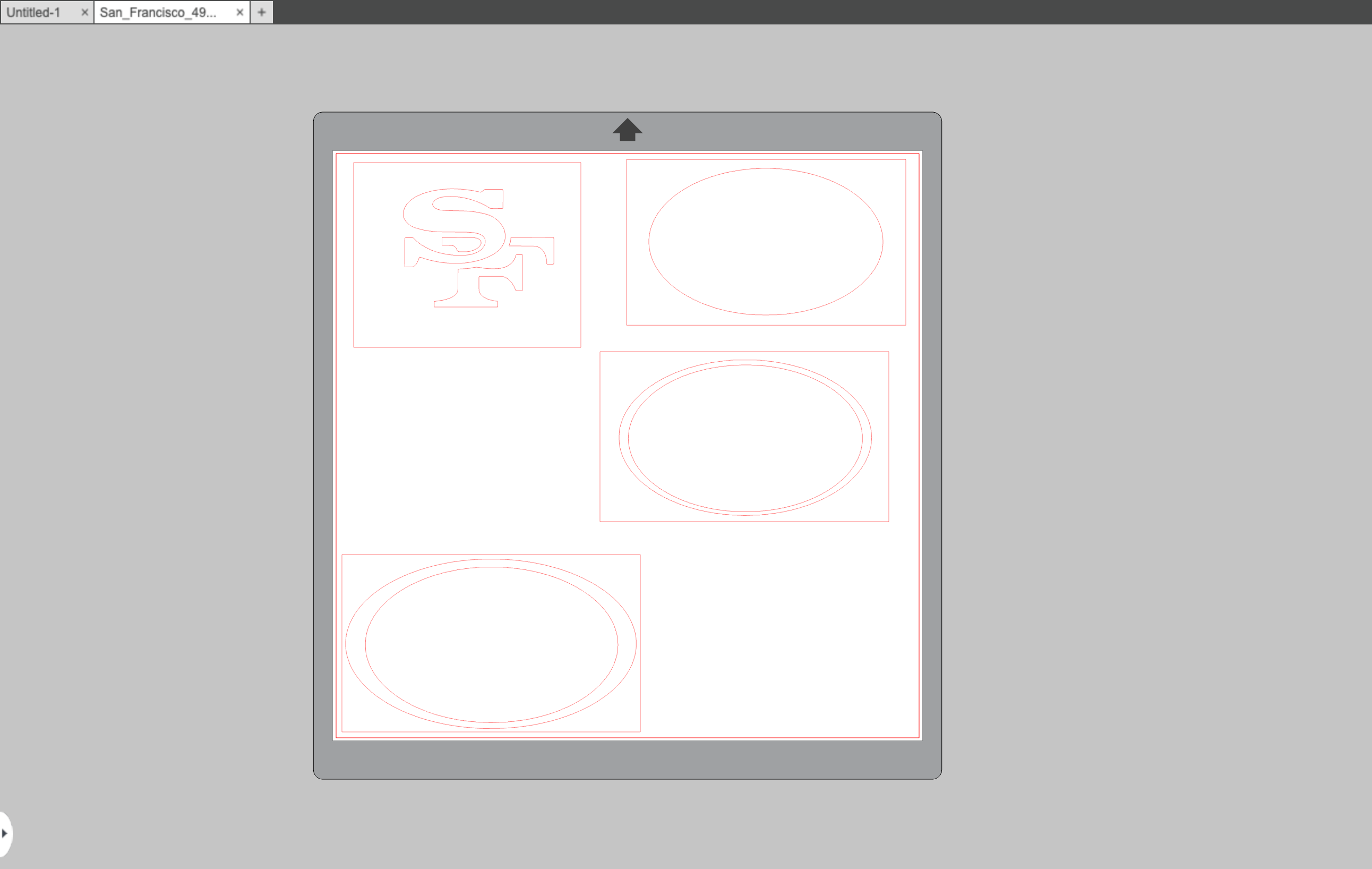
I then opened the image in a new Silhouette Studios design. In order to prepare the image for vinyl cutting, I had to first trace it. Tracing an image in silhouette studio converts it from a raster image (JPG, PNG, PDF) to vector lines that the machine will be able to recognize. To do so, I first clicked the Trace tool in the right panel of the Silhouette Studios workspace. This opened up the trace menu, which contained a button called Select Trace Area. I clicked it and then selected an area around my entire image as the trace area.
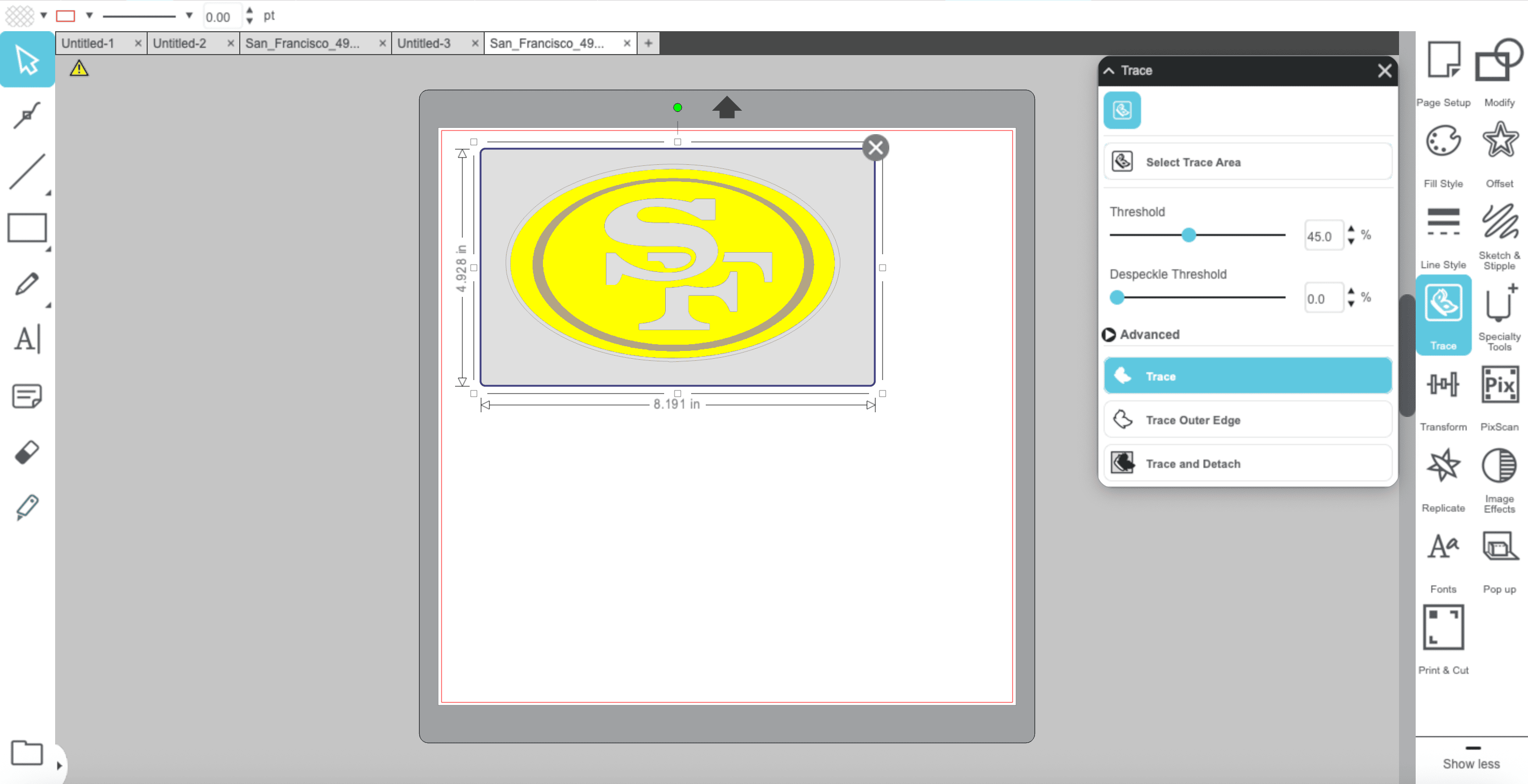
Once done, I clicked "Trace" and the logo was succesfully converted.
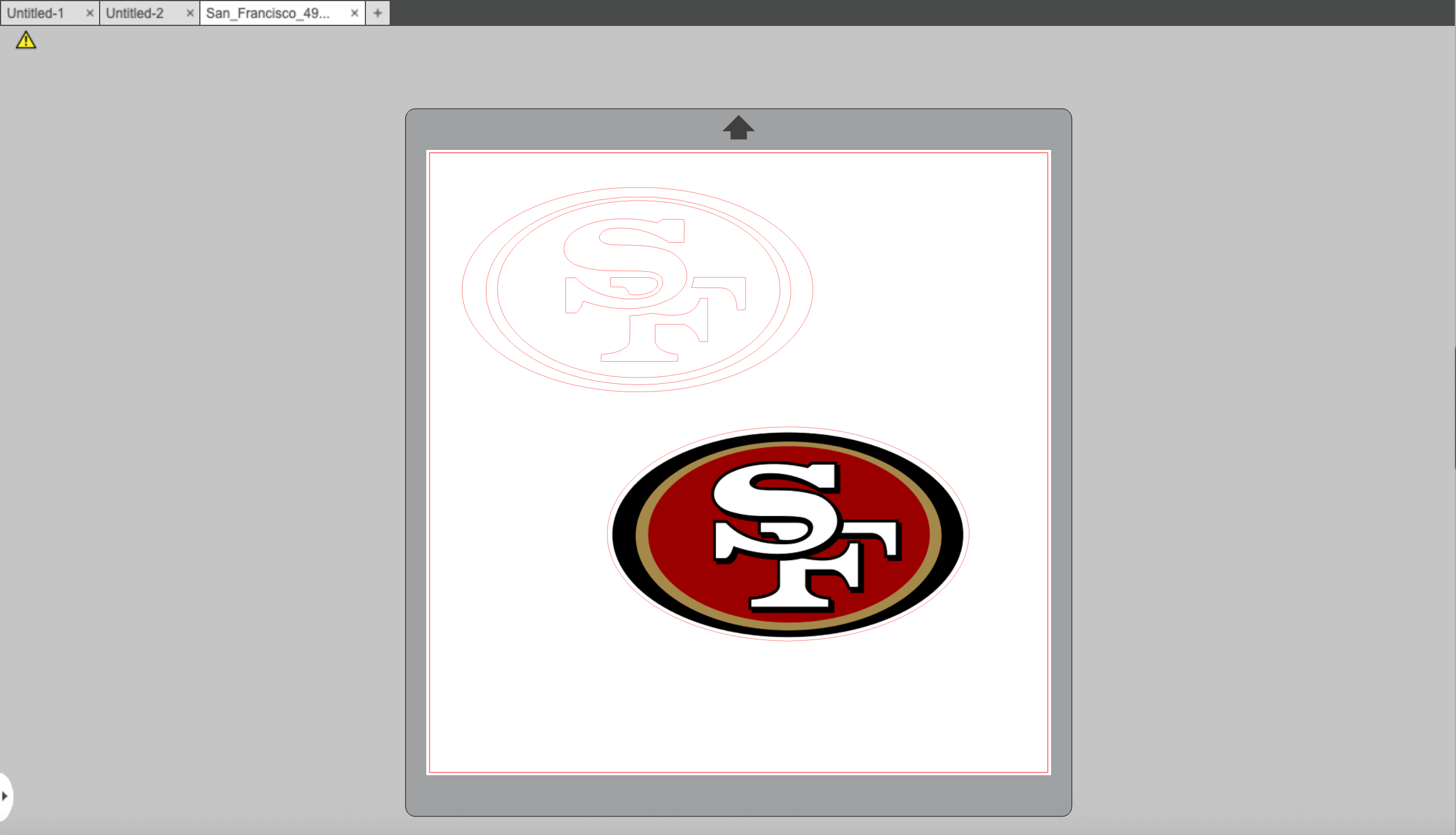
Since my design contained multiple colors, which meant that I would have to cut on multiple sheets of vinyl, I needed to separate each part and cut them individually. To do this, I selected the traced design, right-clicked it, and then hit Release Compound Path. This separated each floating piece of the design, making each path its own, separate object. This allowed me to take apart the design and make individual cut areas for each color. I made sure that they were all an appropriate distance away from each other so that all the vinyl sheets could fit and the entire design could be cut at once.
You can download my Silhouette Studio file here
Using the Cameo Vinyl Cutter
Before cutting, I needed to gather all the vinyl colors for my design. My design contained red, gold, black, and white. Using my fab lab's resources, I was able to find the correct sheets.
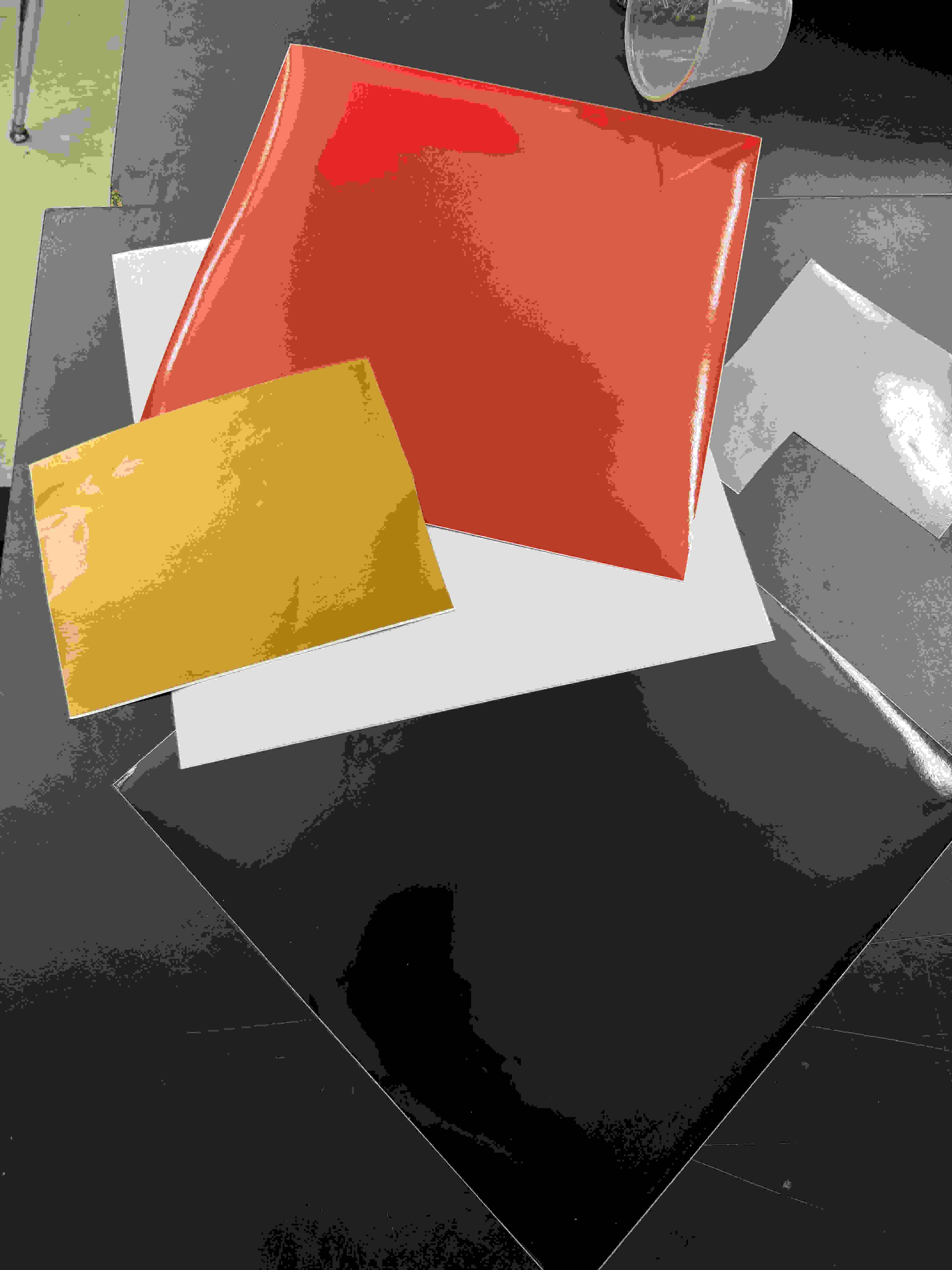
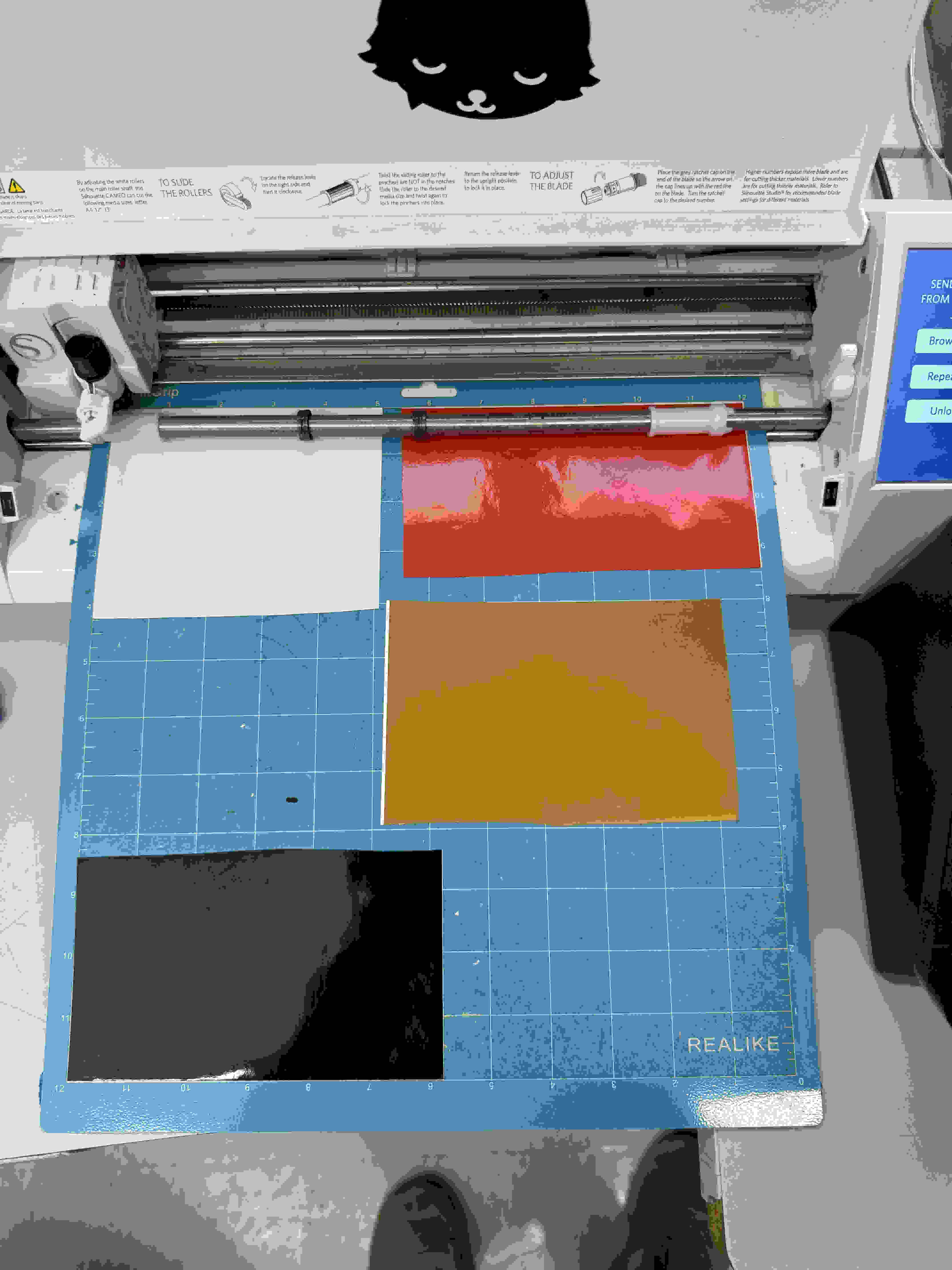
I then trimmed down each sheet so that they could all fit on one cutting mat. I made sure to carefully arrange each peice on the mat so that their location alligned with the location of each part in the design. This made sure that vinyl cutter would accurately cut each segment. Once the cutting mat and vinyl were properly set up, I loaded the cutting mat into the Cameo vinyl cutter.
Sending the Design to the Vinyl Cutter
With the cutting mat loaded, I navigated to the Send tab in Silhouette Studio to prepare the design for cutting. In the send panel, I selected my material type by changing it to Glossy Vinyl. This setting adjusts the blade depth and cutting speed to match the specific material, ensuring clean cuts without damaging the vinyl or the cutting mat.
After confirming my material settings, I clicked the Send button to transmit the design to the vinyl cutter. The machine began cutting each segment of my design according to the paths I had traced earlier.
Cutting Results
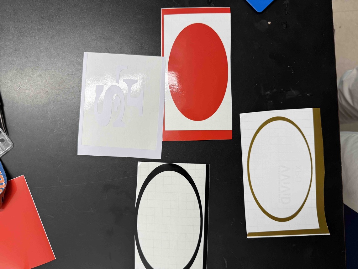
Once the cutting was complete, I unloaded the mat and examined the results. Here is what the cutting mat with vinyl looked like right after the cut.
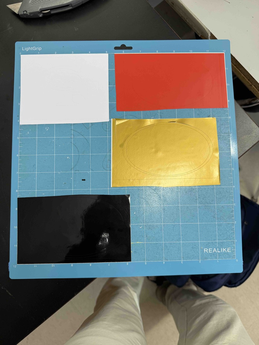
During inspection, I noticed that the black vinyl was slightly unaligned. A very marginal portion was cut off from the top of the black oval. This misalignment was likely caused by the vinyl sheet shifting slightly on the mat during cutting, but the error was minimal enough that it wouldn't significantly impact the final sticker.
Assembling the Sticker
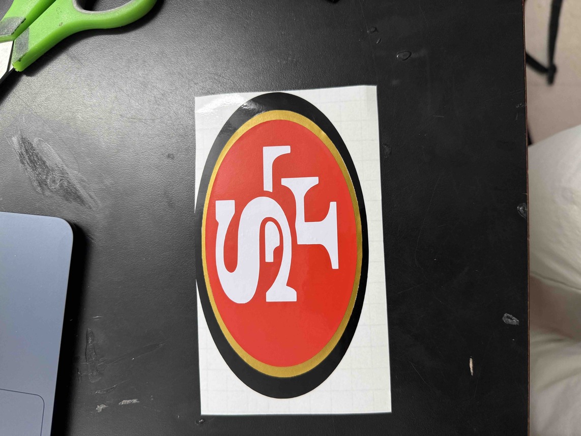
With all pieces cut, I began the process of assembling the sticker. I used tweezers to carefully separate the stickers from the excess vinyl and remove each sticker from the white base. This process required precision to avoid tearing or stretching the vinyl pieces.
Next, I used transfer tape to lift each piece from its backing. I had to be extremely careful in order to align each sticker properly. The process was very tedious to make them fit together, as the multiple layers needed to line up precisely to recreate the 49ers logo accurately. I started with the larger base pieces and gradually added the smaller details, checking alignment after each placement.
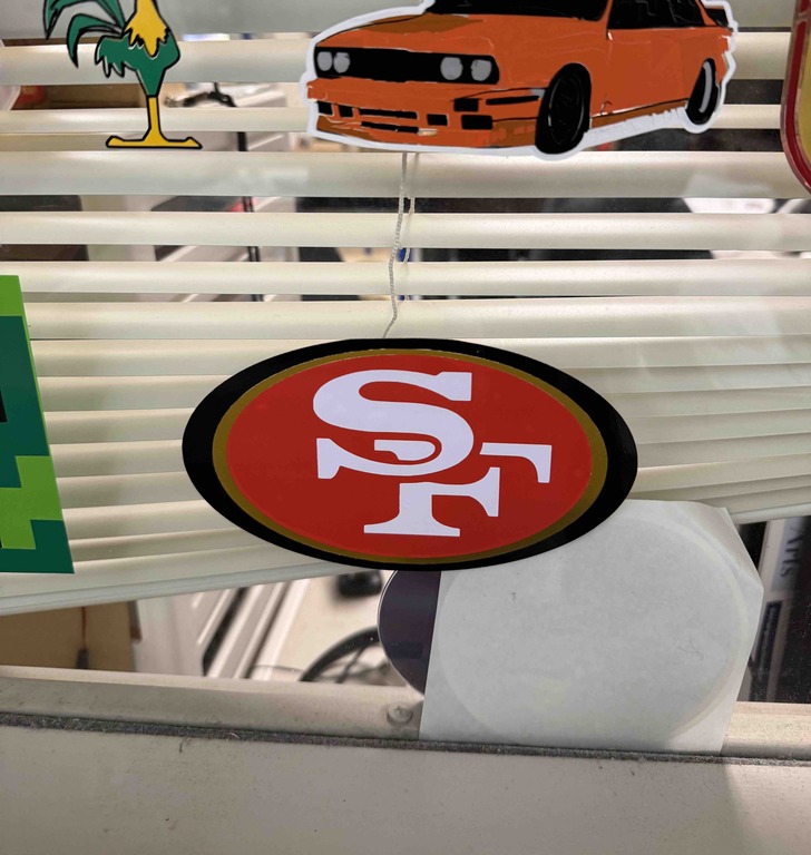
Once I finished assembling all the layers, I placed the sticker on the window of our Fab Academy office with transfer tape still attached.
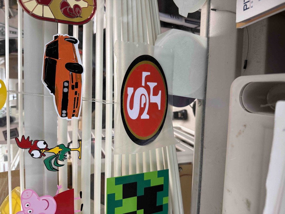
After carefully pressing the sticker onto the window to ensure it adhered properly, I slowly peeled back the transfer tape, leaving the completed 49ers logo on the glass.
Parametric Construction Kit and Laser Cutting
What a Parametric Construction Kit Is
For this week, I created a parametric construction kit design for computer-controlled cutting, specifically laser cutting. A parametric construction kit is a set of 2D parts that are designed with adjustable dimensions (parameters), then cut flat, and finally assembled into a 3D form. In this case, each piece is cut from cardboard as a 2D profile, but the slits and geometry allow multiple pieces to interlock and build a larger 3D structure.
The main advantage of this approach is flexibility in part design. Instead of redrawing everything whenever one measurement changes, I can update key dimensions (like material thickness or slot depth), and the whole part updates consistently. This is especially useful in laser cutting because kerf, material thickness, and fit tolerance all directly affect whether pieces snap together cleanly. It also makes iteration much faster and reduces waste, since I can fine-tune one design and generate many compatible pieces.
Inspiration and Reference Project
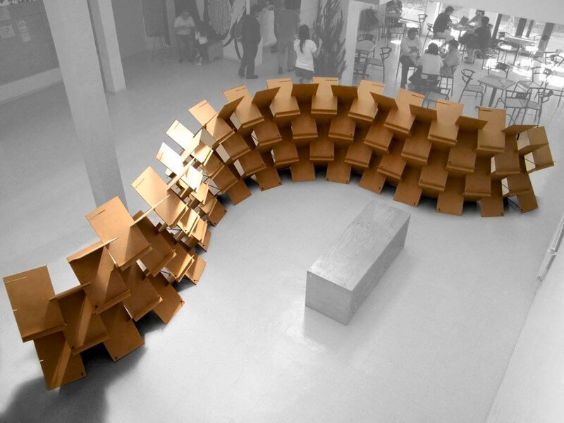
Before sketching my own part, I looked at parametric wall systems online and found a project called Pixel Wall on Parametric House:
https://parametrichouse.com/pixel-wall/
This project shows a flexible, self-supporting wall made from repeated laser-cut plates. The system is considered parametric because the final wall behavior comes from a repeatable module that can be controlled and varied through parameters while still staying within one coherent design logic.
From what I could gather on the page, the Pixel Wall project focuses on combining parametric design with digital fabrication to create a low-cost system with reduced environmental impact. The page also references the research team and institutions involved, and links to more information about the project context.
I used this project as inspiration for my individual design. Here is one of the images I referenced.
Designing My Parametric Piece in Fusion 360
To start my own process, I created a new Fusion 360 design and opened a new sketch. I then drew a base rectangle sized 38 mm x 64 mm and began removing sections to create the interlocking slits.
For the top and bottom slits, the depth had to be exactly 19 mm (half of the total 38 mm width). This was important because when two pieces slide together, they need to sit flushly at the center so there are no protruding edges. Keeping that half-depth relationship made the piece seamless and helped it work cleanly with other copies of the same part.
For the middle slits, the exact depth was less strict. I mainly made sure they were equal to each other, deep enough to hold the connected parts, and still flexible enough for easy assembly.
When sizing each slit, I also designed around my cardboard thickness, which was 3.8 mm. I made each slit width 3.8 mm so that the pieces could fit together directly.
Here is my finished Fusion sketch design before converting everything into user-defined parameters.
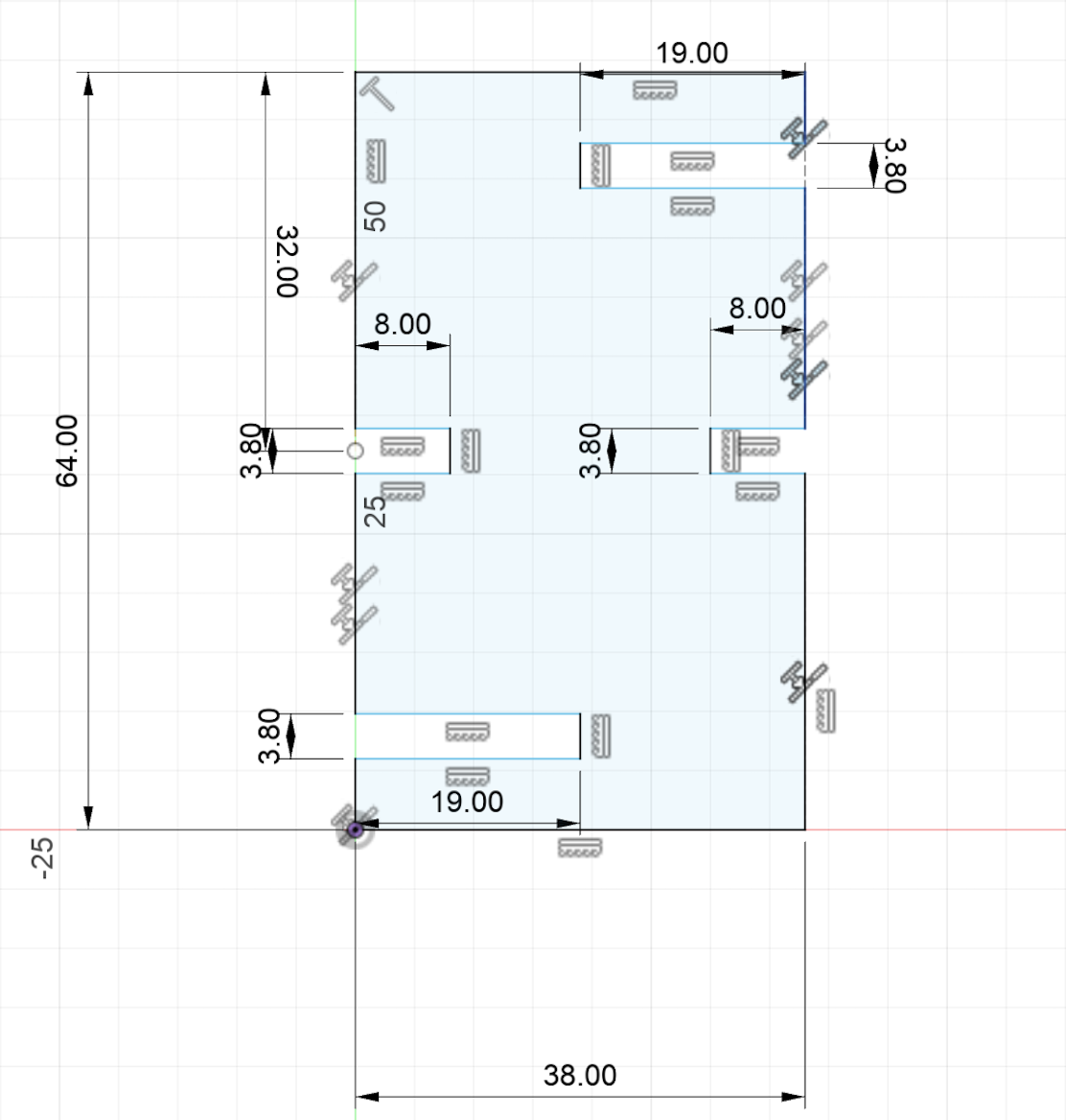
Fusion 360 automatically generated several values in Model Parameters under Change Parameters, which gave me a strong starting point. Since some dimensions had different parameter names but identical values, I standardized them to use matching values so the design would behave more parametrically and stay consistent during edits.
Once this was complete, I exported the Fusion sketch as a .dxf file to prepare it for laser cutting.
You can download my parametric piece design here.
Laser Cutting
I began the laser cutting process by opening my .dxf file in CorelDRAW. This allowed me to verify scale, linework, and placement before sending anything to the laser.
Here is what my piece looked like in Corel:
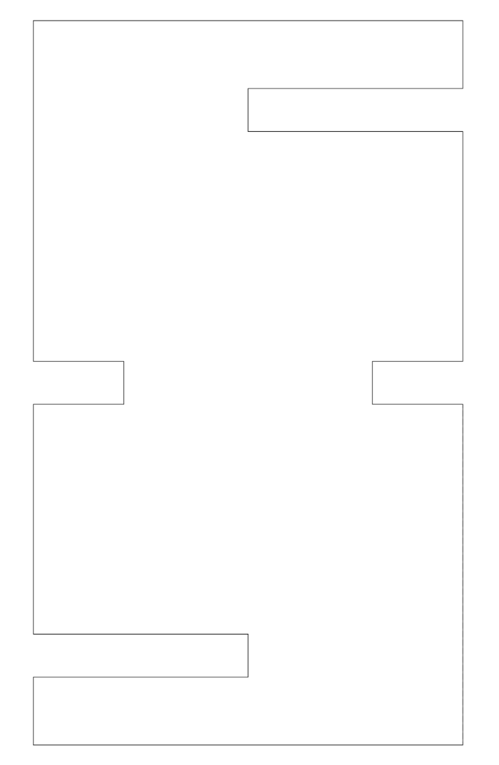
After confirming that one piece was correct, I duplicated it until I had 16 identical copies ready to cut. This step really showed one of the biggest advantages of parametric design: once one part is dimensioned correctly, I can reproduce as many matching parts as needed with confidence that they will all fit together.
Lab Safety Training and Standard Procedures
Before cutting, my group and I completed our lab's safety training. We went over emergency response and normal operating procedures for the Epilog Fusion workflow.
One of the most important items we reviewed was the fire blanket. We learned when to use it (small, contained flare-ups) and how to apply it correctly by covering the flame to cut off oxygen, rather than waving or throwing it from a distance. We also reviewed that if anything fails during a job or if a fire starts, we should immediately stop the machine and call for an adult/instructor.
Along with that, we followed standard shop protocol: never leave the laser unattended while cutting, check material type before starting, confirm focus and settings, keep the work area clear, and make sure we know where emergency equipment is located.
For the Epilog Fusion process itself, we followed the standard sequence: prepare vectors in Corel, send the file to the Epilog print driver, choose the correct material settings, focus the machine, and only then begin the cut.
Sending to the Epilog Fusion and Cutting
After setup, I sent the design to our Epilog Fusion laser cutter software and selected the correct cut settings for cardboard. Once everything looked correct, I clicked Print.
Then I used the cutter's auto-jog to focus the laser nozzle and started the job.
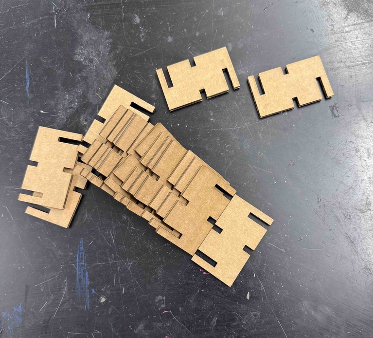
Here is what the pieces looked like immediately after cutting:
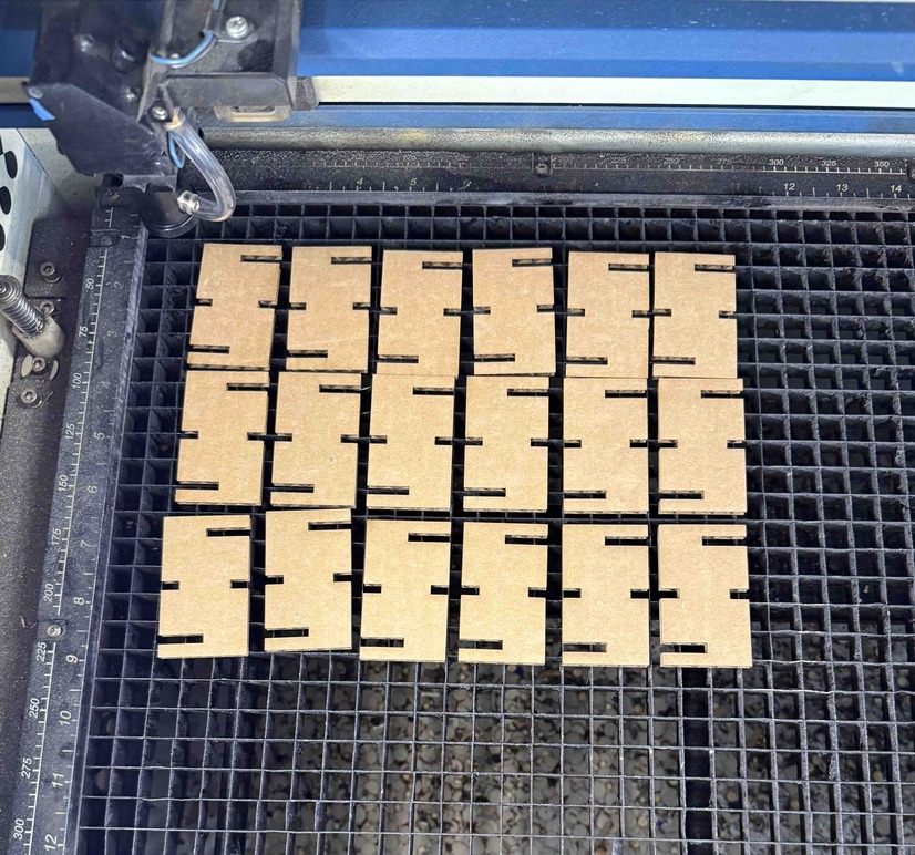
After the cut finished, I removed the pieces from the machine. Each one was identical in outline and slot placement, which confirmed that the CAD-to-cut workflow stayed consistent.
Here is an image showing all of the cut pieces:
Testing Fit and Assembly
After removing everything, I started testing different combinations to see how the parts would behave. The pieces fit flushly together and could be assembled in multiple ways, which is another major strength of parametric design: repeatable geometry gives predictable connections while still allowing flexibility in final form.
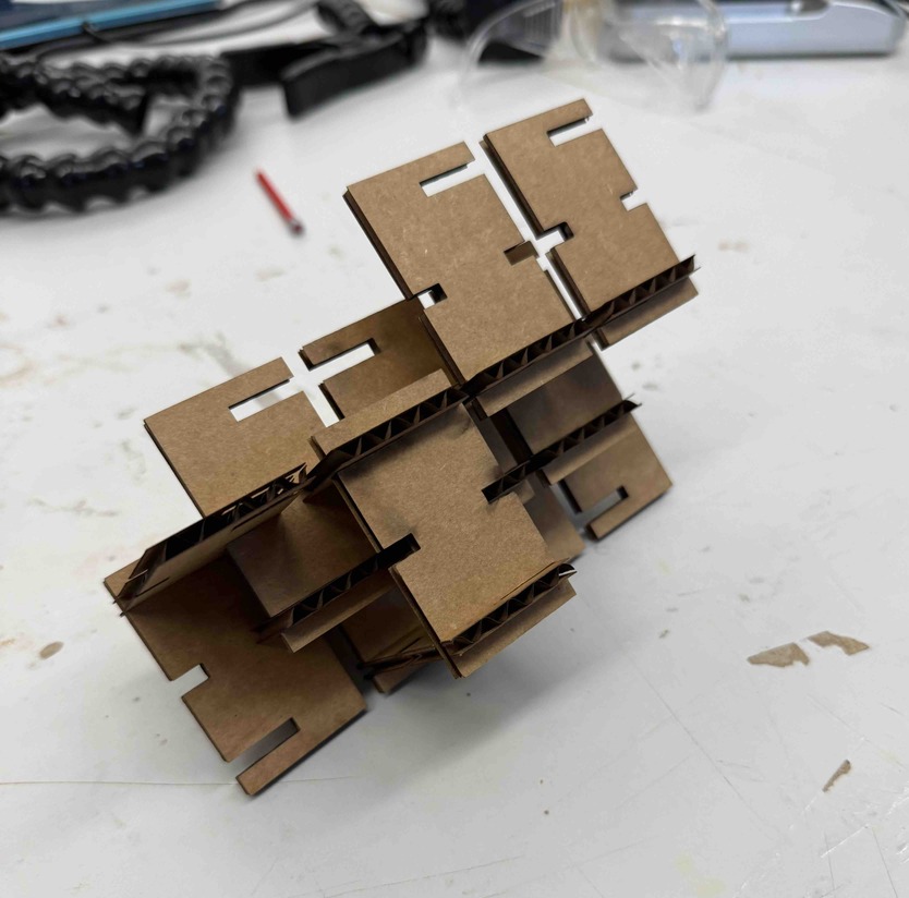
Here is what I built with the pieces during assembly testing:
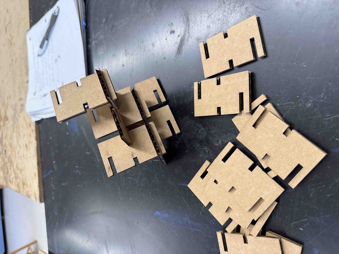
After experimenting with different layouts, I built this final design using the 16 pieces:
Reflection
Overall, this week taught me a lot about both sides of computer-controlled cutting. On the vinyl cutting side, I learned how much setup and alignment matter, especially when layering multiple colors. On the laser cutting side, I learned how CAD precision, material thickness, and machine setup all work together to determine whether a construction kit actually assembles cleanly.
The main mistake I made this week was in my vinyl process, where one section became slightly misaligned after the material shifted. Even though the issue was small, it was a good reminder that even tiny setup errors can affect final quality.
For the parametric kit, the biggest takeaway was that spending more time on dimensional logic up front makes fabrication much smoother later. Because my slot widths and depths were consistent, all 16 laser-cut parts were interchangeable and fit flushly during assembly.
By the end of this week, I had a much better understanding of computer-controlled cutting as a full workflow, not just a machine step. Design decisions in CAD, safety habits in the lab, and machine settings at the cutter all directly impact the final result.